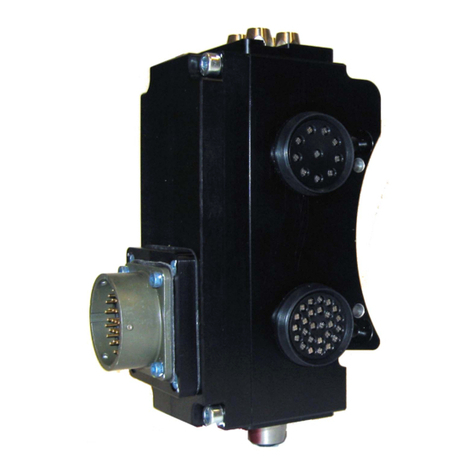
Manual, Fluid/Air, FS2
Document #9620-20-D-FS2-04
Pinnacle
Park
•
1031
Goodworth
Drive
•
Apex,
NC
27539
•
T
el:
919.772.01
15
•
Fax:
919.772.8259
•
www.ati-ia.com • Email: [email protected] D-7
5. Troubleshooting and Service Procedures
This troubleshooting section provides information to help diagnose conditions with the Tool Changer or air module
as well as service procedures for component replacement.
WARNING: Do not perform maintenance or repair(s) on the Tool Changer or modules unless
the Tool is safely supported or placed in the tool stand, all energized circuits (e.g. electrical,
air, water, etc.) are turned off, pressurized connections are purged and power is discharged
from circuits in accordance with the customer’s safety practices and policies. Injury or
equipment damage can occur with the Tool not placed and energized circuits on. Place the
Tool in the tool stand, turn off and discharge all energized circuits, purge all pressurized
connections, and verify all circuits are de-energized before performing maintenance or
repair(s) on the Tool Changer or modules.
5.1 Troubleshooting Procedures
Refer to the following table for troubleshooting information.
Table 5.1—Troubleshooting
Symptom Possible Cause Correction
Fluid/Air Leakage
Damaged/Worn seals
Replace O-rings, U-cup seal, and rubber bushings
as needed. Refer to Section 5.2.1—Master Side
Self-Sealing Valve and Section 5.2.2—Tool Side
Self-Sealing Valve and Section 5.2.3—Rubber Bushing
Replacement
Debris blocking valve seal Clean in and around valve components. Ensure uid
stream is free of large particulates; lter as necessary.
Bent stem
Replace stem. Refer to Section 5.2.1—Master Side
Self-Sealing Valve. Check module attachment to Tool
Changer. Check robot program and ensure parallel
approach trajectory during Tool Changer coupling.
Corrosion Consult ATI for assistance.
Fluid spray during
uncoupling Surge/Water Hammer
Decrease pressure differential between supply and
return lines or install pressure compensation system
(e.g., accumulator or surge suppressor as close as
possible to spraying port).
Poor Flow Flow path blockage Inspect valve components and supply/return lines for
blockage, clean/repair as necessary.
Debris blocking valve seal Clean in and around valve components. Ensure uid
stream is free of large particulates; lter as necessary.
Modules Won't
Couple Bent stem, dowel pin
Replace stem, dowels as necessary. Check module
attachment to Tool Changer. Check robot program
and ensure parallel approach trajectory during Tool
Changer coupling. Refer to Section 5.2.1—Master
Side Self-Sealing Valve and Section 5.2.2—Tool Side
Self-Sealing Valve.
