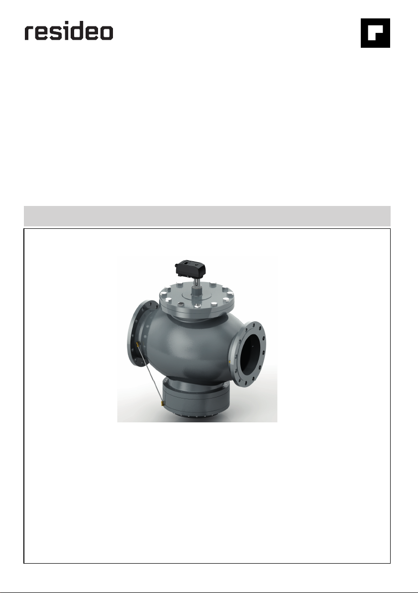
resideo Braukmann V5006TF User manual
Other resideo Control Unit manuals

resideo
resideo Braukmann RV281 User manual

resideo
resideo Braukmann D05FS-EF User manual

resideo
resideo Braukmann SG150 User manual

resideo
resideo Braukmann D05F-EF User manual

resideo
resideo Braukmann D15SN User manual

resideo
resideo Braukmann DR300 User manual

resideo
resideo SV9540 User manual

resideo
resideo Braukmann L5 Series User manual

resideo
resideo RV283P User manual

resideo
resideo Braukmann BA295D-1/2ASC User manual

resideo
resideo Braukmann D05FT User manual

resideo
resideo Braukmann BA295D-3/4WH User manual

resideo
resideo Braukmann R295SA User manual

resideo
resideo Braukmann RV277 User manual

resideo
resideo VR8300A User manual

resideo
resideo Braukmann VWS02Y032W-L5 User manual

resideo
resideo BA295S User manual

resideo
resideo Braukmann VWS02Y032W-L5 User manual

resideo
resideo Braukmann BA295CS User manual

resideo
resideo Braukmann RV280 User manual


Popular Control Unit manuals by other brands

Festo
Festo Compact Performance CP-FB6-E Brief description

Elo TouchSystems
Elo TouchSystems DMS-SA19P-EXTME Quick installation guide

JS Automation
JS Automation MPC3034A user manual

JAUDT
JAUDT SW GII 6406 Series Translation of the original operating instructions

Spektrum
Spektrum Air Module System manual

BOC Edwards
BOC Edwards Q Series instruction manual

KHADAS
KHADAS BT Magic quick start

Etherma
Etherma eNEXHO-IL Assembly and operating instructions

PMFoundations
PMFoundations Attenuverter Assembly guide

GEA
GEA VARIVENT Operating instruction

Walther Systemtechnik
Walther Systemtechnik VMS-05 Assembly instructions

Altronix
Altronix LINQ8PD Installation and programming manual