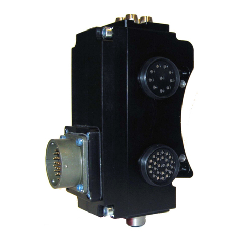
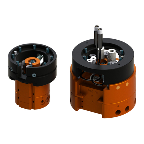
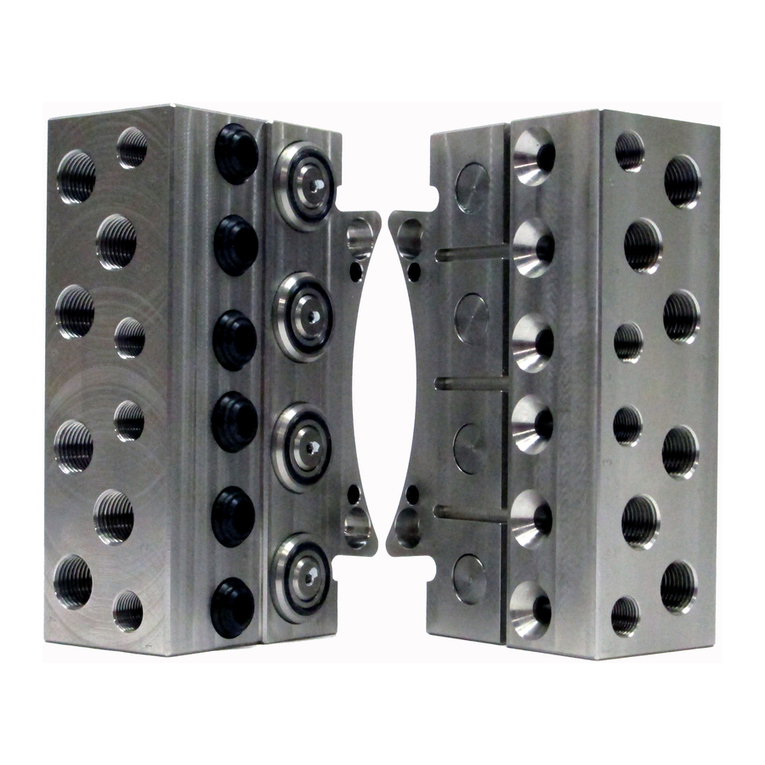
ATI Technologies X7GL User manual

Manual, Electrical Module, X7GL
Document #9620-20-E-X7GL-02
Pinnacle Park • 1031 Goodworth Drive •Apex, NC 27539 • Tel: 919.772.0115 • Fax: 919.772.8259 • www.ati-ia.com
E-1
Table of Contents
E. Electrical Modules....................................................................................................................E‑2
X7GL—Electrical Module.............................................................................................................E‑2
1. Product Overview..................................................................................................................E‑2
1.1 X7GL Master Module..................................................................................................................E‑2
1.2 X7GL Tool Module......................................................................................................................E‑2
2. Installation .............................................................................................................................E‑3
2.1 Module Installation.....................................................................................................................E‑3
2.2 Module Removal.........................................................................................................................E‑4
3. Operation ...............................................................................................................................E‑4
4. Maintenance...........................................................................................................................E‑5
4.1 Cleaning Procedure ...................................................................................................................E‑6
5. Troubleshooting and Service Procedures..........................................................................E‑7
5.1 Troubleshooting.........................................................................................................................E‑7
5.2 Service Procedures....................................................................................................................E‑8
5.2.1 Seal Replacement...........................................................................................................E-8
6. Serviceable Parts ..................................................................................................................E‑9
6.1 Module Mounting Fasteners......................................................................................................E‑9
6.2 Accessories................................................................................................................................E‑9
7. Specications ........................................................................................................................E‑9
8. Drawings ..............................................................................................................................E‑10

Manual, Electrical Module, X7GL
Document #9620-20-E-X7GL-02
Pinnacle Park • 1031 Goodworth Drive •Apex, NC 27539 • Tel: 919.772.0115 • Fax: 919.772.8259 • www.ati-ia.com
E-2
E. Electrical Modules
X7GL—Electrical Module
1. Product Overview
The X7GL modules provide a connection to customer tooling. When the modules are coupled, the V‑ring seal forms
a water resistant but not waterproof seal.
1.1 X7GL Master Module
The X7GL Master module includes: (1) Lemo ERA female connector and a V‑ring seal. Refer to Section 8—
Drawings for additional information and connector details.
1.2 X7GL Tool Module
The X7GL Tool module includes: (1) Lemo ERA female connector. Refer to Section 8—Drawings for
additional information and connector details.
Figure 1.1—X7GL Modules
X7GL Master Module
V-ring Seal
X7GL Tool Module
(4) M4 Socket Flat Head Cap Screw
Shield Ring
Spring Probe
(4) M4 Socket Flat Head Cap Screw
Lemo ERA
Female Connector
Lemo ERA
Female Connector

Manual, Electrical Module, X7GL
Document #9620-20-E-X7GL-02
Pinnacle Park • 1031 Goodworth Drive •Apex, NC 27539 • Tel: 919.772.0115 • Fax: 919.772.8259 • www.ati-ia.com
E-3
2. Installation
Electrical modules are typically installed by ATI prior to shipment. Installation and removal are outlined in the
following section. For wiring information, refer to Section 8—Drawings.
WARNING: Do not perform maintenance or repair(s) on the Tool Changer or modules unless
the Tool is safely supported or placed in the tool stand, all energized circuits (e.g. electrical,
air, water, etc.) are turned o, pressurized connections are purged and power is discharged
from circuits in accordance with the customer specic safety practices and policies. Injury
or equipment damage can occur with the Tool not placed and energized circuits on. Place
the Tool in the tool stand, turn o and discharge all energized circuits, purge all pressurized
connections, and verify all circuits are de-energized before performing maintenance or
repair(s) on the Tool Changer or modules.
CAUTION: Thread locker applied to fasteners must not be used more than once. Fasteners
might become loose and cause equipment damage. Always apply new thread locker when
reusing fasteners.
2.1 Module Installation
Tools required: 2.5 mm hex key, torque wrench
Supplies required: Clean rag, Loctite®222
1. Place the Tool in a secure location.
2. Uncouple the Master and Tool plates.
3. Turn o and de‑energize all energized circuits (for example: electrical, pneumatic, hydraulic).
4. Clean the mounting surfaces.
5. Align the optional module on the Master or Tool plate as shown in Figure 2.1.
6. Apply Loctite 222 to (4) M4 socket at head cap screws.
7. Secure module with (4) M4 mounting fasteners using a 2.5 mm hex key and tighten to
10 in‑lbs (1.13 Nm).
8. Safely resume normal operation.
Figure 2.1—Module Installation
Tool Plate Assembly
(QC-41 Shown)
Master Plate Assembly
(QC-41 Shown)
(4) M4 Socket Flat
Head Cap Screw
X7GL Tool Module
(4) M4 Socket Flat
Head Cap Screw
X7GL Master Module

Manual, Electrical Module, X7GL
Document #9620-20-E-X7GL-02
Pinnacle Park • 1031 Goodworth Drive •Apex, NC 27539 • Tel: 919.772.0115 • Fax: 919.772.8259 • www.ati-ia.com
E-4
2.2 Module Removal
Refer to Figure 2.1
Tools required: 2.5 mm hex key
1. Place the Tool in a secure location.
2. Uncouple the Master and Tool plates.
3. Turn o and de‑energize all energized circuits (for example: electrical, pneumatic, hydraulic).
4. Disconnect any cables, air line, etc (if required).
5. Using a 2.5 mm hex key, remove the (4) M4 socket at head cap screws and lift the module from the
Master or Tool plate.
3. Operation
To maximize the service life of these components, the following points should be observed:
CAUTION: Never couple or uncouple the modules unless electrical power has been
disconnected and discharged both upstream and downstream from the modules. Arcing and
contact damage occur during coupling or uncoupling if power is not removed and discharged.
Always disconnect and discharge power from upstream and downstream of the modules
before coupling or uncoupling.
CAUTION: Improper cable routing can result in wires and cables being pinched in the joint
between the Tool Changer plates and premature failure of the electrical connectors. Properly
route and secure all cables, particularly on the Master side.

Manual, Electrical Module, X7GL
Document #9620-20-E-X7GL-02
Pinnacle Park • 1031 Goodworth Drive •Apex, NC 27539 • Tel: 919.772.0115 • Fax: 919.772.8259 • www.ati-ia.com
E-5
4. Maintenance
Under normal conditions, no special maintenance is necessary; however, it is recommended that periodic
inspections be performed to assure long‑lasting performance and that unexpected damage has not occurred. The
modules are not designed to be eld serviced as all point‑to‑point wiring connections are soldered.
DANGER: This module has a voltage of 50V or greater; always remove power before
contacting the module. Arcing and damage occur if power is not removed from the module
during maintenance or service. Always remove power before attaching or disconnecting
cables, separating or inserting the mating couplers, or making any contact with the Tool
Changer or Utility Coupler.
WARNING: Do not perform maintenance or repair(s) on the Tool Changer or modules unless
the Tool is safely supported or placed in the tool stand, all energized circuits (e.g. electrical,
air, water, etc.) are turned o, pressurized connections are purged and power is discharged
from circuits in accordance with the customer specic safety practices and policies. Injury
or equipment damage can occur with the Tool not placed and energized circuits on. Place
the Tool in the tool stand, turn o and discharge all energized circuits, purge all pressurized
connections, and verify all circuits are de-energized before performing maintenance or
repair(s) on the Tool Changer or modules.
If the Tool Changer is used in dirty environments (e.g., welding or deburring applications), limit the exposure of the
Tool Changer. Idle Tool assemblies should be covered to prevent debris from settling on the mating surface.Also,
the Master assembly should be exposed for only a short period of time during Tool change and down time. Perform
the following visual inspections monthly:
• Inspect mounting fasteners to verify they are tight. If loose, then tighten to the proper torque.
Refer to Section 2—Installation.
• Cable connections should be inspected during maintenance periods to ensure they are secure. Loose
connections should be cleaned and re‑tightened, as appropriate. Inspect cable sheathing for damage and repair
or replace damaged cabling. Loose connections or damaged cabling should not occur during normal operation
and may indicate improper routing and/or strain relieving.
• Inspect the Master and Tool pin blocks for pin damage, debris or darkened pins. Refer to Section 4.1—
Cleaning Procedure.
• Inspect V‑ring seals for wear, abrasions, and cuts. If worn or damaged, replace. Refer to Section 5.2.1—
Seal Replacement.
Manual, Electrical Module, X7GL
Document #9620-20-E-X7GL-02
Pinnacle Park • 1031 Goodworth Drive •Apex, NC 27539 • Tel: 919.772.0115 • Fax: 919.772.8259 • www.ati-ia.com
E-6
4.1 Cleaning Procedure
Tools required: Nylon Brush (ATI Part Number 3690‑0000064‑60)
1. Place the Tool in a secure location.
2. Uncouple the Master and Tool plates.
3. Turn o and de‑energize all energized circuits (for example: electrical, pneumatic, hydraulic).
4. Inspect the Master and Tool pin blocks for debris or blackened center pin and shielding ring.
Figure 4.1—Inspect Master and Tool Pin Blocks
Note: Pin blocks shown are for
illustration purposes only.
Debris
Blackened Pins
5. If debris or blackened center pin and shielding ring are present, use a vacuum to remove the debris, and
clean using a nylon brush (ATI Part Number 3690‑0000064‑60).
NOTICE: Do not use an abrasive media, cleaners, or solvents to clean the center pin and
shielding ring. Using abrasive media, cleaners, or solvents will cause damage to the contact
surface, or cause center pin and shielding ring to stick. Clean contact surfaces with a vacuum or
non‑abrasive media such as a nylon brush (ATI Part Number 3690‑0000064‑60)
Figure 4.2—Clean Pin Blocks with a Nylon Brush
6. Safely resume normal operation.

Manual, Electrical Module, X7GL
Document #9620-20-E-X7GL-02
Pinnacle Park • 1031 Goodworth Drive •Apex, NC 27539 • Tel: 919.772.0115 • Fax: 919.772.8259 • www.ati-ia.com
E-7
5. Troubleshooting and Service Procedures
The following section provides troubleshooting and service information to help diagnose conditions and repair
the X7GL modules.
WARNING: Do not perform maintenance or repair(s) on the Tool Changer or modules unless
the Tool is safely supported or placed in the tool stand, all energized circuits (e.g. electrical,
air, water, etc.) are turned o, pressurized connections are purged and power is discharged
from circuits in accordance with the customer specic safety practices and policies. Injury
or equipment damage can occur with the Tool not placed and energized circuits on. Place
the Tool in the tool stand, turn o and discharge all energized circuits, purge all pressurized
connections, and verify all circuits are de-energized before performing maintenance or
repair(s) on the Tool Changer or modules.
5.1 Troubleshooting
Troubleshooting information is provided in the following table.
Table 5.1—Troubleshooting
Symptom Possible Cause Correction
Signal(s)
malfunctioning
Contact pins are separating when
Tool Changer is coupled.
Ensure that the Tool Changer has proper pneumatic
connections and supplied air is to the proper
specication. Refer to the Tool Changer section of this
manual for air supply requirements.
Tool Changer is coupling and
uncoupling under a load.
Revise operating procedures to only couple/uncouple
with power disconnected and discharged. Field
replacement of module contacts is not possible.
Cables are damaged, for example:
pinched, torn, or fatigued Examine cables for damage; perform a continuity test
on cables and replace damaged cables
Debris caught between the Master
and Tool modules. Clean probes and shield rings. Refer to Section 4.1—
Cleaning Procedure

Manual, Electrical Module, X7GL
Document #9620-20-E-X7GL-02
Pinnacle Park • 1031 Goodworth Drive •Apex, NC 27539 • Tel: 919.772.0115 • Fax: 919.772.8259 • www.ati-ia.com
E-8
5.2 Service Procedures
Component replacement and adjustment procedures are provided in the following section.
5.2.1 Seal Replacement
Parts required: Refer to Section 8—Drawings.
The seal protects the electrical connection between the Master and Tool module. If the seal
becomes worn or damaged, replace the seal.
1. Place the Tool in a secure location.
2. Uncouple the Master and Tool plates.
3. Turn o and de‑energize all energized circuits (for example: electrical, pneumatic, hydraulic).
4. To remove the existing seal, pinch the edge of the seal, and pull the seal away from the pin
block on the Master module.
5. To install a new seal, stretch the new seal over the shoulder of the pin block.
6. Push the seal hub down against the pin block.
7. Safely resume normal operation.
Figure 5.1—V‑ring Seal Replacement
V-ring Seal
Stretch seal over shoulder of pin block
and push seal hub down against
the pin block with finger tip
V-ring Seal
Pinch edge of seal with
fingers and gently pull
away from pin block

Manual, Electrical Module, X7GL
Document #9620-20-E-X7GL-02
Pinnacle Park • 1031 Goodworth Drive •Apex, NC 27539 • Tel: 919.772.0115 • Fax: 919.772.8259 • www.ati-ia.com
E‑9
6. Serviceable Parts
For mounting fasteners and accessories, refer to the following tables. For additional serviceable parts, refer to
Section 8—Drawings.
6.1 Module Mounting Fasteners
Table 6.1—Master and Tool Module
Item No. Qty Part Number Description
* 4 3500-1262012-15A M4x12 Flat Head Socket Cap Screw, 10.9, ISO10642/
DIN7991, ES‑ATI‑007, YL M‑Spheres/IFI 525
6.2 Accessories
Table 6.2—Accessories
Item No. Qty Part Number Description
* * 3690‑0000064‑60 Nylon Brush
7. Specications
Table 7.1—MasterSpecications
9120‑X7GL‑M High Voltage Master Module with Lemo connector for Ultrasonic Weld Applications
Connector(s) (1) Lemo ERA female connector
Electrical Rating 4A, 1.4kV
Enclosure IP40
Weight TBD
Table 7.2—ToolSpecications
9120‑X7GL‑T High Voltage Tool Module with Lemo Connector for Ultrasonic Weld Applications
Connector(s) (1) Lemo ERA female connector
Electrical Rating 4A, 1.4kV
Enclosure IP40
Weight TBD

Manual, Electrical Module, X7GL
Document #9620-20-E-X7GL-02
Pinnacle Park • 1031 Goodworth Drive •Apex, NC 27539 • Tel: 919.772.0115 • Fax: 919.772.8259 • www.ati-ia.com
E-10
8. Drawings
3rd ANGLE PROJECTION
COUPLED
77.8 (APX.)
"
DANGER!
-
For electrical modules using > 60VDC or 42 VAC, NO contact
should be attempted before removing power. This especially
includes separation or insertion of the mating connectors
or any contact with the tool changer or its components."
44.9
X7GL Master Module
(9120-X7GL-M)
ERA.1S.405.CTA
Lemo, Female connector
Serviceable Part
(V-Ring)
4010-0000030-01
33.3
ERA.1S.405.CTA
Lemo, Female connector
60.2
42.6
60.6 62.1
40.3
28.6
59.7
42.6
60.7
62.2
28.6
40.3
X7GL Tool Module
(9120-X7GL-T)
Notes:
1. Internal wiring: Discrete Wires.
2. Shield Isolated from Chassis Ground.
X7GL Wiring
X7GL-M ----------> >---------- X7GL-T
(Straight Through)
(Discrete Wires)
(Shield Isolated From Chassis)
Rev.
Description
Initiator
Date
01
Initial Issue
PDL
03/01/12
B
1:1
1 1
REVISION
NOTES: UNLESS OTHERWISE
SPECIFIED.
DO NOT SCALE DRAWING.
ALL DIMENSIONS ARE IN
MILLIMETERS.
DRAWN BY:
CHECKED BY:
P.Luczka, 3/1/12
W.Berrocal, 3/2/12
TITLE
SCALE
SIZE
DRAWING NUMBER
PROJECT #
SHEET OF
9630-20-X7GL
120301-1
01
PROPERTY OF ATI INDUSTRIAL AUTOMATION, INC. NOT TO BE REPRODUCED IN ANY
MANNER EXCEPT ON ORDER OR WITH PRIOR WRITTEN AUTHORIZATION OF ATI.
1031 Goodworth Drive, Apex, NC 27539, USA
Tel: +1.919.772.0115 Email: [email protected]
Fax: +1.919.772.8259 www.ati-ia.com
ISO 9001 Registered Company
L.Jamshidi, 3/2/12
X7GL Ultrasonic Weld Module w/ Isolated Connector
This manual suits for next models
2
Table of contents
Other ATI Technologies Control Unit manuals

ATI Technologies
ATI Technologies QC-11HM User manual

ATI Technologies
ATI Technologies FS2 User manual

ATI Technologies
ATI Technologies UA8 User manual

ATI Technologies
ATI Technologies PROFINET DL10 User manual

ATI Technologies
ATI Technologies PROFINET DL12 User manual

ATI Technologies
ATI Technologies VB12-M User manual

ATI Technologies
ATI Technologies SC29 User manual