Quick-Change Installation and Operation Manual
Document #9620-20-H-UAx-13
Pinnacle Park
•
1031 Goodworth Drive
•
Apex, NC 27539
•
Tel: 919.772.0115
•
Fax: 919.772.8259
•
www.ati-ia.com
•
Email: info@ati-ia.com
H - 6
2.6 Tool Module Swivel Removal
1. Remove the retaining ring from the swivel. Note: If retaining ring is a snap type ring use snap ring
pliers to remove the retaining ring.
2. Remove the swivel from the housing.
3. Operation
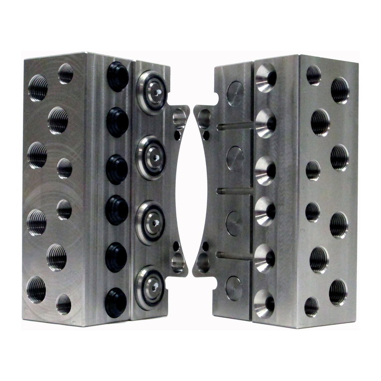
The Utility Stud Feed modules are designed to pass studs/air from the Master to the Tool for use by the
customer’s tooling. A unique, patented stud feed-through mechanism has been developed by ATI for this
application. A spring-loaded ball joint mechanism is used to transfer solid studs between the mating halves.
This produces self-alignment between the Master and Tool sides, while simultaneously allowing axial and
rotational degrees of freedom to the feed tube. Traditionally, the feed tube looses its flexibility at the joint to
the tool changer and therefore this location is prone to premature failure from excessive strain. Using a large
tube bend radius at this joint only somewhat alleviates the problem. ATI’s method allows the joint to maintain
its flexibility and therefore completely eliminates any strain on the tube. After passing through the tool
changer, the Master and Tool halves of the tube behave as one integral unit.
To provide a large bend radius to the tube, the feed-through attachment is offset from the center of the tool
changer, thereby providing ample clearance from the robot wrist. Extension arms of various lengths are
available from ATI to provide this offset.
Electrical Modules can attach to the Utility Module Extension Arm. Refer to the corresponding specific
electrical module section of the modular manual for further detail.
4. Maintenance
Once installed, the operation of the Utility Stud Feed modules is generally trouble-free. Periodically, the
condition of the spherical joints should be checked. Replace any damaged or degraded components as
necessary.
Electrical Modules can attach to the Utility Module Extension Arm. Refer to the corresponding specific
electrical maintenance instructions for further detail.
Under normal conditions, no special maintenance is necessary, however it is recommended that periodic
inspections be performed to assure long-lasting performance and to assure that unexpected damage has not
occurred. Perform the following visual inspection monthly:
Inspect mounting fasteners to verify they are tight and if loose, then tighten to the proper torque.
Cable connections should be inspected during maintenance periods to ensure they are secure. Loose
connections should be cleaned and re-tightened as appropriate. Inspect cable sheathing for damage, repair or
replace damaged cabling. Loose connections or damaged cabling are not expected and may indicate improper
routing and/or strain relieving.
Inspect the O-ring seal on the swivel for wear or damage. If worn or damaged, replace. Refer to Section 4.1—
O-Ring Seal Replacement.
WARNING: Do not perform maintenance or repair on Tool Changer or modules unless
the tool is safely supported or docked in the tool stand and all energized circuits (e.g.
electrical, air, water, etc.) have been turned off. Injury or equipment damage can occur
with tool not docked and energized circuits on. Dock the tool safely in the tool stand and
turn off all energized circuits before performing maintenance or repair on Tool Changer
DANGER: For electrical modules using > 60VDC or 42VAC, NO contact should be
attempted before removing power. This includes attaching and disconnecting cables or
any contact with the Tool Changer or its components. Arcing and damage will occur if
this is not observed. Remove power before attaching, disconnecting any cables or
attempting any maintenance of Tool Changer.
