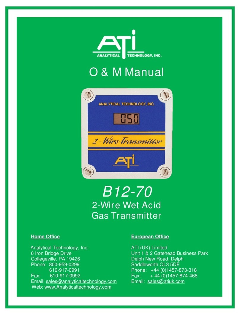
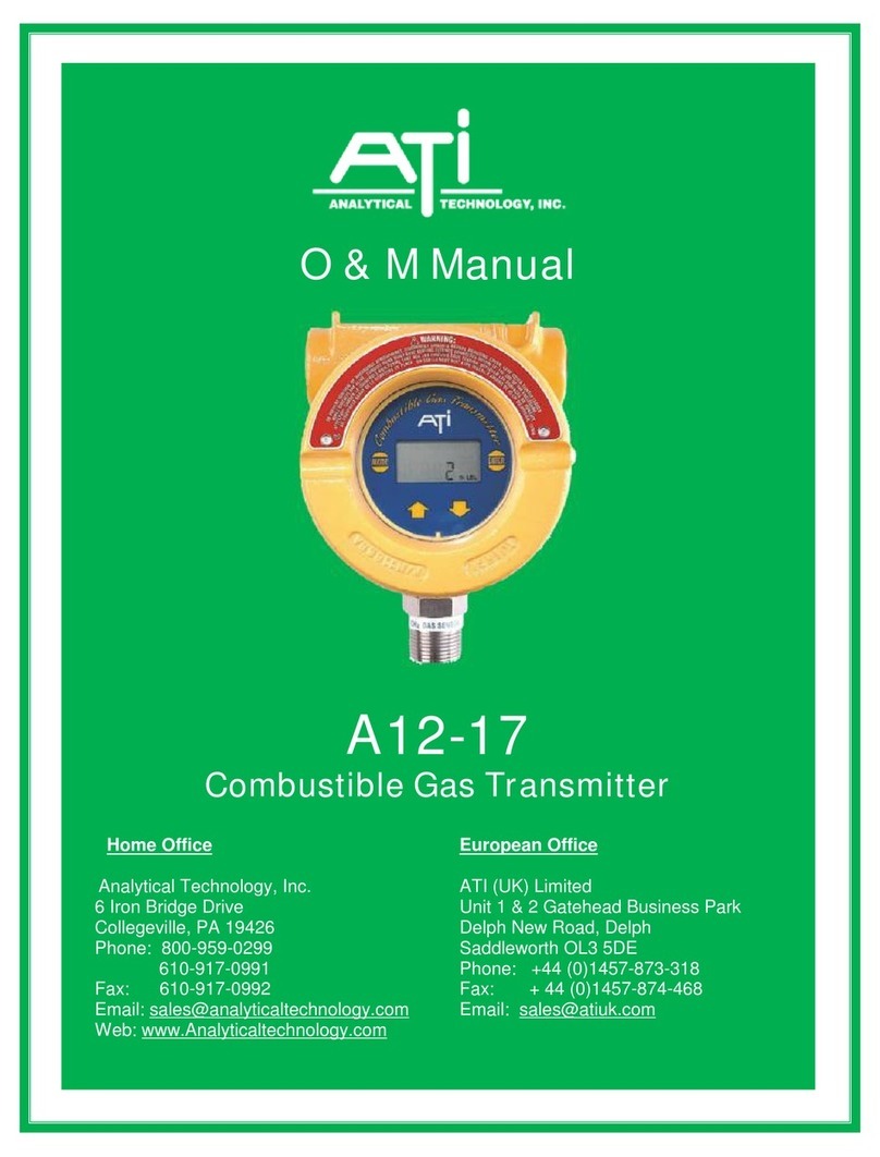
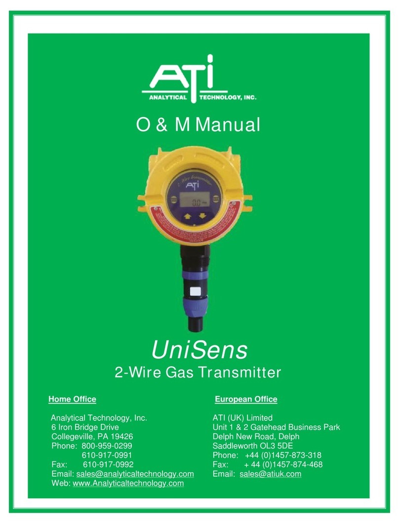
ATI Technologies D12 EX-IR Series User manual

Fax: 610-917-0992 Fa
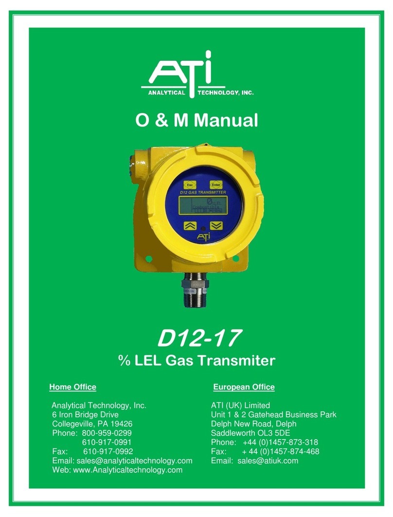
O & M Manual
Series D12
EX-IR
Gas Transmitter
w/Smart IR Sensor
Home Office European Office
Analytical Technology, Inc. ATI (UK) Limited
6 Iron Bridge Drive Unit 1 & 2 Gatehead Business Park
Collegeville, PA 19426 Delph New Road, Delph
Phone: 800-959-0299 Saddleworth OL3 5DE
610-917-0991 Phone: +44 (0)1457-873-318
Fax: 610-917-0992 Fax: + 44 (0)1457-874-468
Web: www.Analyticaltechnology.com

D12EX-IR Gas Transmitter with IR Smart Sensor
x: + 4457-874-468
Table of Contents
SAFETY.............................................................................. 5
WARNINGS .......................................................................... 5
SPECIFIC CONDITIONS OF USE /SCHEDULE OF LIMITATIONS:.......... 5
MARKINGS........................................................................... 5
CERTIFICATIONS .................................................................... 6
HAZARDOUS LOCATION INSTALLATION REQUIREMENTS (ATEX /
IECEX)................................................................................ 6
INTRODUCTION................................................................. 7
D12EX-IR GAS TRANSMITTER.................................................... 7
OPTIONS ............................................................................. 7
IR SENSOR ........................................................................... 8
IR Sensor Versions ........................................................ 5
HC LEL Range Hydrocarbon Sensor .............................. 5
HHC High Range HydrocarbonSensor .......................... 8
CO2-L Low Range Carbon Dioxide Sensor .................... 9
CO2-H High Range Carbon Dioxide Sensor................. 10
SYMBOLS........................................................................... 10
SPECIFICATIONS .............................................................. 11
INSTALLATION................................................................. 12
MECHANICAL MOUNTING..................................................... 12
Hazardous Locations.................................................. 12
Gas Density Considerations........................................ 12
Transmitter Mounting................................................ 13
Remote Junction Box.................................................. 14
ELECTRICAL CONNECTIONS.................................................... 15
Board Stack ................................................................ 15
Battery Replacement ................................................. 16
Power Supply Board ................................................... 17
Communication Jumper ............................................. 18
Remote Sensor Option ............................................... 19
Wiring Examples ........................................................ 20
OPERATION..................................................................... 28
OPERATOR INTERFACE PANEL ................................................ 28
Touch Keys ................................................................. 28
Menus and Settings.................................................... 29
Moving the Cursor and Selecting ............................... 29
Editing Settings .......................................................... 29
STARTUP ........................................................................... 30
Transmitter Review .................................................... 30
Sensor Review ............................................................ 31
Main Display .............................................................. 32
Main Reading............................................................. 32
Trouble Indication ...................................................... 33
Main Display Timeout ................................................ 33
Main Display Alarm Inhibit Method........................... 33
POP-UP DISPLAYS................................................................ 33
Sensor Removed Display.............................................33
Sensor Installed ..........................................................34
MAIN MENU ......................................................................34
Main Menu .................................................................34
Alarm Active Menu.....................................................35
SENSORS............................................................................36
IR Sensor Cells.............................................................36
Sensor Menus .............................................................37
Sensor Settings Menu .................................................38
Sensor Model Menu....................................................38
Sensor Target Gas Menu ............................................38
Sensor Target Gas Setup Menu ..................................39
Sensor Range Menu....................................................39
Sensor Calibration ......................................................41
Sensor Calibration Menu ............................................42
ALARMS.............................................................................46
Flammable and Toxic Gas Alarms ..............................46
Process Low Alarms ....................................................46
Gas Alarm Operation..................................................47
Alarm Indicators .........................................................48
Alarms Menu ..............................................................49
Alarm Inhibit...............................................................52
Alarm Test Menu ........................................................53
Trouble Alarm.............................................................54
DATA-LOG..........................................................................58
Data Log Menu...........................................................58
Data Log Setup Menu .................................................59
Data Log View Menu ..................................................59
Data Log Print Menus, Methods, and Settings...........61
I/O...................................................................................64
I/O Menu ....................................................................64
4-20mA Output...........................................................64
COM Menus and Settings ...........................................66
Relay Operation, Menus, and Settings .......................72
PANEL ...............................................................................75
Panel Menu ................................................................75
Display Menu..............................................................75
Security Menu.............................................................76
SYSTEM .............................................................................79
System Menu..............................................................79
Clock Menu.................................................................79
Reset Menu.................................................................79
Version Menu .............................................................80
APPENDIX A.....................................................................82
CAPTURING AND CHARTING A DATA-LOG REPORT......................82
Serial Connection........................................................82
Capturing with HyperTerminal ...................................82
Charting with Microsoft Excel ....................................86
PRODUCT WARRANTY..........................................................91
D12EX-IR Gas Transmitter with IR Smart Sensor
Dec 2019 ( 85-0004 Rev A)
4
List of Figures
FIGURE 1. D12EX-IR GAS TRANSMITTER .............................................7
FIGURE 2SENSOR INSTALLED.............................................................8
FIGURE 3SENSOR HOUSING COVER REMOVED .....................................8
FIGURE 4SENSOR HOUSING COMPONENTS..........................................8
FIGURE 54&5PIN IR SENSOR CELLS.................................................8
FIGURE 6. OVERALL DIMENSIONS .....................................................13
FIGURE 7. ELECTRONIC BOARD STACK................................................15
FIGURE 8. “POWER SUPPLY”BOARD CONNECTIONS. ...........................17
FIGURE 9. COMM.CONFIGURATION ..................................................18
FIGURE 10. REMOTE SENSOR CONNECTIONS ......................................19
FIGURE 11. EXAMPLE OF POWER ONLY,NO 4-20MACONNECTION ........20
FIGURE 12. EXAMPLE 4-20MA3-WIRE CONNECTION ..........................21
FIGURE 13. EXAMPLE 4-20MA4-WIRE DUAL SUPPLY CONNECTION ......22
FIGURE 14. EXAMPLE 3-WIRE TO ATI A17/B14 RECEIVER...................23
FIGURE 15. EXAMPLE HART 3-WIRE “POINT-TO-POINT”.....................24
FIGURE 16. EXAMPLE HART MULTIDROP 3-WIRE ...............................25
FIGURE 17. EXAMPLE RS485 “MULTI-DROP”CONNECTIONS ................26
FIGURE 18. EXAMPLE RS232 COM PORT CONNECTION ......................27
FIGURE 19. OPERATOR INTERFACE PANEL ..........................................28
FIGURE 20. EXAMPLE EDIT..............................................................29
FIGURE 21. TRANSMITTER REVIEW DISPLAYS......................................30
FIGURE 22. SENSOR REVIEW DISPLAY ...............................................31
FIGURE 23. MAIN DISPLAY .............................................................32
FIGURE 24. MAIN DISPLAY TROUBLE INDICATION................................33
FIGURE 25. SENSOR REMOVED DISPLAY ............................................33
FIGURE 26. MAIN MENU ................................................................34
FIGURE 27. ALARM ACTIVE MENUSETUP MENU.................................35
FIGURE 28. SETUP MENU...............................................................35
FIGURE 29. SIGNAL OUTPUTS WITH AND WITHOUT GAS. .......................36
FIGURE 30. ABSORPTION SPECTRUM AND SENSOR RESPONSE.................37
FIGURE 31. SENSOR MENU.............................................................37
FIGURE 32. SENSOR SETTINGS MENU ...............................................38
FIGURE 33. SENSOR MODEL MENU..................................................38
FIGURE 34 SENSOR TARGET GAS MENU..............................................38
FIGURE 35 SENSOR TARGET GAS SETUP MENU.....................................39
FIGURE 36. SENSOR RANGE MENU...................................................40
FIGURE 37. DATA-LOG WARNING MESSAGE ......................................40
FIGURE 38. SENSOR CALIBRATION MENU ..........................................42
FIGURE 39. SENSOR ZERO CAL.SETUP ..............................................43
FIGURE 40. SENSOR ZERO_CAL.MENUS............................................43
FIGURE 41 SENSOR SPAN CAL.SETUP ...............................................44
FIGURE 42. SENSOR SPAN CAL.MENUS ............................................44
FIGURE 43 SPAN TO SURROGATE GAS...............................................44
FIGURE 44. SENSOR CALIBRATION HISTORY MENUS ............................45
FIGURE 45. FLAMMABLE AND TOXIC GAS ALARMS. .............................46
FIGURE 46 PROCESS LOW ALARMS...................................................46
FIGURE 47. HIGH ALARM OPERATION...............................................47
FIGURE 48. LOW ALARM OPERATION................................................47
FIGURE 49. ALARM INDICATOR FLAGS...............................................48
FIGURE 50. ALARM ACTIVE MENU ...................................................48
FIGURE 51. ALARM STATUS MENU...................................................48
FIGURE 52. ALARM RESET MENU..................................................... 49
FIGURE 53. ALARMS MENU ............................................................ 49
FIGURE 54. ALARM SETTING MENUS ................................................ 50
FIGURE 55. ALARM INHIBIT MENU................................................... 53
FIGURE 56. ALARM TEST MENU ...................................................... 53
FIGURE 57. TROUBLE INDICATION ON MAIN DISPLAY........................... 54
FIGURE 58. TROUBLE STATUS DISPLAY.............................................. 54
FIGURE 59. DATA LOG MENU ......................................................... 58
FIGURE 60. DATA LOG SETUP MENU................................................ 59
FIGURE 61. DATA LOG VIEW MENU ................................................. 59
FIGURE 62. DATA LOG GRAPH VIEW ................................................ 60
FIGURE 63. DATA LOG GRAPH VIEW MENU....................................... 60
FIGURE 64. DATA LOG SINGLE VIEW MENU....................................... 61
FIGURE 65. DATA LOG PRINT EXAMPLE............................................. 61
FIGURE 66. DATA LOG PRINT MENU ................................................ 62
FIGURE 67. DATA LOG PRINT FORMAT MENU.................................... 62
FIGURE 68. I/O MENU .................................................................. 64
FIGURE 69. GRAPH OF 4-20MAOUTPUT .......................................... 64
FIGURE 70. 4-20MAMENU ........................................................... 65
FIGURE 71. 4-20MACONTROL PAGE................................................ 65
FIGURE 72. ADJUST 4MAMENU ..................................................... 65
FIGURE 73. ADJUST 20MAMENU ................................................... 65
FIGURE 74. COM MENU ............................................................... 66
FIGURE 75. COM SETUP MENU...................................................... 67
FIGURE 76. HART MENU ............................................................... 68
FIGURE 77. HART IDENTIFICATION MENU.......................................... 69
FIGURE 78. HART FIND-DEVICE DISPLAY ........................................... 70
FIGURE 79. MODBUS MENU........................................................... 70
FIGURE 80 ALARM RELAY DIAGRAM.................................................. 73
FIGURE 81. RELAYS MENU.............................................................. 74
FIGURE 82. RELAYS MENU.............................................................. 74
FIGURE 83. RELAY SETUP MENU...................................................... 74
FIGURE 84. PANEL MENU............................................................... 75
FIGURE 85. DISPLAY MENU ............................................................ 75
FIGURE 86. SECURITY MENU........................................................... 76
FIGURE 87. ACTIVATING SECURITY ................................................... 76
FIGURE 88. DEACTIVATING SECURITY................................................ 77
FIGURE 89. CHANGING THE SECURITY CODE....................................... 78
FIGURE 90. SYSTEM MENU............................................................. 79
FIGURE 91. CLOCK MENU............................................................... 79
FIGURE 92. RESET MENU ............................................................... 79
FIGURE 93. VERSION MENU ........................................................... 80

D12EX-IR Gas Transmitter with IR Smart Sensor
Dec 2019 ( 85-0004 Rev A)
5
SAFETY
Read and understand this manual before installing, operating, or maintaining the D12EX-IR Transmitter.
Pay particular attention to the warnings and cautions below. All of the warnings and cautions shown here
are repeated in the appropriate sections of the manual.
WARNINGS
•To prevent ignition of hazardous atmospheres, do not remove cover while circuits are live.
•KEEP ASSEMBLY TIGHTLY CLOSED WHEN IN OPERATION.
•Installation must be in accordance with the recognized standards of the appropriate authority in
the country concerned.
•Servicing of this unit must be performed by trained personnel.
•Before servicing, ensure local regulations and site procedures are followed.
•To prevent ignition of flammable or combustible atmospheres, disconnect power before
servicing.
•The transmitter must be earthed/grounded for electrical safety and to limit the effects of radio
frequency interference. An Earth ground points is provided inside the unit.
•Operate only in the specified temperature range.
•Verify transmitter after installation, after service events, and periodically to ensure the safety and
integrity of the system.
•No User Serviceable Parts
•Flameproof joints are not permitted to be repaired.
•Do not place in service if damaged.
SPECIFIC CONDITIONS OF USE /SCHEDULE OF LIMITATIONS:
•To minimize the risk of electrostatic charge, provisions shall be made for adequate grounding and
equipment shall be installed in such a manner so that accidental discharge shall not occur.
•The enclosure that features the Gas Sensor Housing must be properly mounted with the sensor
opening facing downwards.
•Flameproof joints are not intended to be repaired.
MARKINGS
ANALYTICAL TECHNOLOGY, INC.
COLLEGEVILLE, PA 19426 USA
Model: D12EX-IR-a-b
Power: 12 - 30 VDC, 250 mA MAX
Tamb: -20°C to +60°C

D12EX-IR Gas Transmitter with IR Smart Sensor
Dec 2019 ( 85-0004 Rev A)
6
CERTIFICATIONS
DEMKO 18 ATEX 2066X
CE 0539 II 2 G Ex db IIC T6 Gb
- EN 60079-0:2012+A11:2013
- EN 60079-1:2014
IECEx UL 18.0080X
Ex db IIC T6 Gb
• IEC 60079-0 (2011-06) + Corr.1 (2012-01) + Corr. 2(2013-12) + I-SH 01(2013-11) + I-SH 02 (2014-10)
• IEC 60079-1, 7th Edition (2014-06)
HAZARDOUS LOCATION INSTALLATION REQUIREMENTS (ATEX /IECEX)
• Read and understand this manual prior to installation and use.
• Use rated Ex db IIC Gb entry devices
• All un-used ports must be closed with blanking elements rated Ex db IIC Gb
• All fittings are 3/4" NPT.
• Mount transmitter with sensor housing facing down.

D12EX-IR Gas Transmitter with IR Smart Sensor
Dec 2019 ( 85-0004 Rev A)
7
INTRODUCTION
D12EX-IR GAS TRANSMITTER
The D12Ex-IR gas transmitter is used to continuously monitor for leaks of combustible hydrocarbon gas
in ambient air near process tanks, piping, or in enclosed spaces where gases may accumulate. Standard
sensors are available for detecting methane and propane, and numerous other process and solvent gases
like hexane and toluene. Sensors are also available for detecting CO2 with upper ranges of 5000 PPM,
5% by volume, and 100% by volume.
The transmitter features an easily replaceable NDIR (non-dispersive
infrared) sensor “cell”, a non-intrusive four button user interface
with a back-lighted graphics display, three level alarm system with
three (optional) alarm relays, high-resolution 4-20mA current loop
output, real-time clock, data-logger, and optional HART™ or
Modbus™ network interface. The housing is explosion proof, and
is UL rated for use in hazardous locations (see specifications). The
sensor may be located up to 100’ from the transmitter using the
optional remote junction box
Figure 1. D12Ex-IR Gas Transmitter
OPTIONS
The transmitter is available with options to meet the needs of most applications. The “Alarm Relay”
option includes a special power supply board that provides power for three SPDT relays, the display
backlight, and a selectable RS232/485 interface for Modbus™ and ASCII communication. The “HART”
option provides a HART™ FSK interface and may be ordered with or without the Alarm Relay option.
The table below summarizes the available options.
Table 1 Transmitter Options
Option
Description
Remote Sensor Junction Box
Permits the gas sensor to be located up to 100 feet from the transmitter
using only 4 wires.
Alarm Relays
Provides (3) SPDT relays
Modbus RTU
Enables Modbus RTU protocol over RS232 and RS485
HART FSK
Enables HART device (includes the internal HART FSK modem)
HART DDL available on the HART Foundation website.

D12EX-IR Gas Transmitter with IR Smart Sensor
Dec 2019 ( 85-0004 Rev A)
8
IR SENSOR
The IR sensor consists of the IR cell mounted within an explosion-proof, stainless steel housing. The
base of the housing is threaded into the transmitter, or (optional) remote housing, and connects the cell to
the transmitter’s electronics. The housing cover threads onto the base and is fitted with a flame arrestor,
which permits gas to reach the cell while preventing ignition of any combustible atmosphere that could
develop around the transmitter. The cover may be removed to replace the cell, if the need should arise.
Figure 2 Sensor Installed
Figure 3 Sensor Housing Cover Removed
Figure 4 Sensor Housing Components
Figure 5 4 & 5 Pin IR Sensor Cells

D12EX-IR Gas Transmitter with IR Smart Sensor
Dec 2019 ( 85-0004 Rev A)
5
IR Sensor Versions
The table lists the gas sensors available for the D12Ex-IR.
Sensors are not safe for monitoring acetylene.
Table 2. IR Sensor Versions.
Version
Description
HC
Low level hydrocarbon sensor designed for
detecting methane, propane, and various other
flammable gases in air, below their respective LEL.
Also includes a high range setting for monitoring
methane above its UEL.
HHC
High range hydrocarbon sensor designed for 0-100
%VOL concentrations of Propane, Butane, LPAGE,
etc, for monitoring levels above the UEL.
CO2-L
Carbon dioxide sensor designed for lower ranges.
CO2-H
Carbon dioxide sensor designed for higher ranges.
HC LEL Range Hydrocarbon Sensor
The HC version of the IR sensor is designed for detecting leaks of methane, propane, and other
gases in locations where they might occur, but are not normally expected. The NDIR sensor does
not distinguish one gas from another, but is calibrated to report levels of the selected “target gas”,
much like a catalytic bead sensor. Unlike a catalytic bead sensor, compounds of silicon do not
poison the sensor, nor does the output decrease when exposed to higher levels of gas. Although
not entirely accurate above the target gas LEL, readings will not decrease when exposed to higher
concentrations of the target gas. By default, the transmitter will alarm when the gas level rises
to 20 and 50 percent of the LEL1.
The HC sensor may also be used for monitoring high levels of methane in locations where it is
normally expected. This is accomplished by selecting the “Methane-HR” setting, which should
only be used for monitoring methane at levels above its UEL2(15 %VOL). Extreme care must be
taken in these locations, since a leak of air could produce an explosive atmosphere.
Many hydrocarbon gases have absorption characteristics that are similar to propane. This allows
gas readings to be produced by scaling the propane reading using a “k-factor”. The transmitter
exposes a collection of these gases for selection as the target gas and maintains the k-factor for
each. When span calibrated to the target gas, the transmitter adjusts the k-factor. The transmitter
also permits span calibration to propane as a “surrogate” gas, when the target gas is unavailable.
The table below summarizes target gas selections available on the sensor.
1LEL (Lower Explosive Limit) of a gas or vapor is defined as the lowest percent by volume of that gas or vapor in air that is
capable of producing a flash of fire in presence of an ignition source (arc, flame, heat). Example: 100 %LEL of methane is 5
%VOL in air.
2Highest %VOL (percent by volume) concentration of a gas or a vapor in air capable of producing a flash of fire in presence of
an ignition source (arc, flame, heat).

D12EX-IR Gas Transmitter with IR Smart Sensor
Dec 2019 ( 85-0004 Rev A)
6
Table 3 HC Sensor Target Gas Selections
(Parenthesis indicate default value)
Designed for monitoring combustible levels below the LEL (Lower Explosive Limit). Accuracy +/-2%LEL
Gas
LEL
%VOL
UEL
%VOL
Range
%LEL
Alarms A/W/C
%LEL
Relative
Density
Propane Rdg3
@100%LEL
Methane
5.00
15.0
20-(100)
50/20/-10
0.55
40
Propane
2.20
10.0
20-(100)
50/20/-10
1.55
100
Designed for monitoring various other hydrocarbon gases below the LEL, readings are produced by scaling the
propane reading using a “k-factor”. Accuracy is +/- 6%LEL 4
Gas
LEL
%VOL
UEL
%VOL
Range
%LEL
Alarms A/W/C
%LEL
Relative
Density
Propane Rdg
@100%LEL
K
Factor
Acetone
2.50
12.80
20-(100)
50/20/-10
1.2
35
3.280
Chloromethane
8.10
17.40
20-(100)
50/20/-10
1.7
74
4.970
Cyclopentane
1.10
8.70
20-(100)
50/20/-10
1.6
31
1.620
Dichloroethane
5.40
11.40
20-(100)
50/20/-10
1.2
29
8.570
Ethane
3.00
12.40
20-(100)
50/20/-10
1.05
135
1.010
Ethanol
3.30
19.00
20-(100)
50/20/-10
1.6
91
1.650
Ethyl acetate
2.00
11.50
20-(100)
50/20/-10
1.2
54
1.690
Ethylene
2.70
36.00
20-(100)
50/20/-10
0.98
43
2.837
Ethylene oxide
3.00
100.00
20-(100)
50/20/-10
1.5
161
0.845
Hexane
1.20
7.50
20-(100)
50/20/-10
1.3
68
0.872
MEK
1.40
11.40
20-(100)
50/20/-10
1.1
34
1.870
Methanol
6.00
36.00
20-(100)
50/20/-10
1.01
123
2.220
n-Butane
1.60
8.40
20-(100)
50/20/-10
2.11
75
0.970
Pentane
1.50
7.80
20-(100)
50/20/-10
1.8
72
0.950
Propanol
2.00
12.70
20-(100)
50/20/-10
1.02
64
1.430
Propylene
2.00
11.10
20-(100)
50/20/-10
1.5
54
1.690
Toluene
1.10
7.10
20-(100)
50/20/-10
1.01
42
1.180
Xylene
1.10
7.00
20-(100)
50/20/-10
1.02
33
1.510
Designed for monitoring methane levels above the UEL (Upper Explosive Limit). Can also “auto-range” with the high
accuracy methane selection above. Accuracy is +/-2%VOL
Gas
LEL
%VOL
UEL
%VOL
Range
%VOL
Alarms A/W/C
%VOL
Relavite
Density
Methane-HR
5.00
15.0
10-(100)
Disabled
0.55
“Methane-HR” is not designed to be used below 15%VOL
3Gas reading at the LEL level when propane is selected as the target gas. This is useful for choosing target gas in multi-gas
enviroments (see “Multiple Gas Environments”).
4These and other gases are available fully calibrated to within +/-2% by special order. Contact the ATi Sales department for
more information.

D12EX-IR Gas Transmitter with IR Smart Sensor
Dec 2019 ( 85-0004 Rev A)
7
%LEL Gases
For safety, when displaying concentrations in units of %LEL, the transmitter’s high-high alarm, “Alarm”
restricts its Type and Reset settings to High and Manu, respectively. The “Warning” and “Caution”
alarms are not restricted, and no alarm may be set above 60 %LEL. The table below lists the alarm
settings. For information about how these settings affect gas alarm operation, see Flammable and Toxic
Gas Alarms on page 46.
Table 4 HC Sensor %LEL Gas Alarm Settings
Alarm Name
Setting
Default Value
Setting Limits
Alarm
Type
Set Level, Reset Level
Set Delay
Reset Delay
Reset (clear method)
High
50 %LEL
0s
Not applicable5
Manual
Not adjustable
10 –60 %LEL
0-10s
Not applicable
Not adjustable
Warning
Type
Set Level, Reset Level
Set Delay
Reset Delay
Reset (clear method)
High
20 %LEL
0s
0s
Automatic
High, Low, or None
-15 to 60 %LEL
0-10s
0-7200s (when Reset=Auto)
Automatic or Manual
Caution
Type
Set Level, Reset Level
Set Delay
Reset Delay
Reset (clear method)
Low
-10 %LEL
0s
0s
Automatic
High, Low, or None
-15 to 60 %LEL
0-10s
0-7200s (when Reset=Auto)
Automatic or Manual
Methane-HR
The “Methane-HR” setting should be selected only for monitoring methane at levels above the UEL
(Upper Explosive Limit), which is defined as the highest %VOL concentration of a gas or a vapor, in air,
capable of producing a flash of fire in presence of an ignition source (arc, flame, heat). For methane, the
UEL is 15 %VOL. Extreme care must be taken in these locations, since any leak of air can produce an
explosive atmosphere. The table below lists the alarm settings. For information about how these settings
affect gas alarm operation, see Flammable and Toxic Gas Alarms on page 46.
This setting is not designed for use
below the UEL of methane.
Table 5 HC Sensor Methane-HR Alarm Settings
Alarm Name
Setting
Default Value6
Setting Limits
(All)
Type
Set Level, Reset Level
Set Delay
Reset Delay
Reset (clear method)
None
50 %VOL
0s
0s
Automatic
High, Low, None
-15 to +120 %Range
0-10s
0-7200s (when Reset=Auto)
Automatic or Manual
5Reset delay is not applicable on manual reset alarms.
6Settings will not appear until the alarm type is changed to “High” or “Low”

D12EX-IR Gas Transmitter with IR Smart Sensor
Dec 2019 ( 85-0004 Rev A)
8
Multiple Gas Environments
The hydrocarbon sensor features a number of target gas selections but it is important to remember that it
cannot distinguish between them. The presence of a hydrocarbon gas that is not selected as the target is
likely to produce a false reading. Monitoring for leaks of more than one gas should be avoided since, at
best, it may lead to false alarms, and at worst, it can lead to a dangerous, undetected, explosive
atmosphere.
Selecting the proper target gas will increase the likelihood of detecting a dangerous gas leak in multiple
gas environments. Data for gases listed in Table 3 on page 6 includes the propane reading that would be
observed if a 100%LEL mixture of the listed gas were present at the sensor. When leaks are possible
from more than one gas species, choose the one with the lowest “Propane Rdg @ 100%LEL”, as the
target gas.
When leaks are possible from more than one gas species,
choose the one with the lowest
“Propane Rdg @ 100%LEL”, as the target gas.
This way, an alarm will occur before any gas reaches an explosive level. A leak from any of the others
will produce a “false alarm”, but safety should be the primary goal.
HHC High Range HydrocarbonSensor
The HHC cell is similar to the HC sensor’s “Methane-HR” setting. It is designed to monitor high
concentrations of other hydrocarbon gases in locations where they are likely to exist normally. Extreme
care must be taken in these locations, since any leak of air can produce an explosive atmosphere. Gas
readings are reported in units of %VOL (percent by volume), and the range is adjustable from 20 to 100
%VOL. The tables below list the target gas selections and alarm settings. For information about how
these settings affect gas alarm operation, see Flammable and Toxic Gas Alarms on page 46.
Table 6 HHC Sensor Target Gas Selections
(Parenthesis indicate default value)
Gas
LEL
%VOL
UEL
%VOL
Range
%VOL
Alarms A/W/C
%VOL
Relative
Density
Propane
2.20
10.0
10-(100)
Disabled
1.55
Table 7 HHC Sensor Alarm Settings
Alarm Name
Setting
Default Value7
Setting Limits
(All)
Type
Set Level, Reset Level
Set Delay
Reset Delay
Reset (clear method)
None
50 %VOL
0s
0s
Automatic
High, Low, None
-15 to +120 %Range
0-10s
0-7200s (when Reset=Auto)
Automatic or Manual
This cell is not designed for use below the UEL of the target gas.
7Settings will not appear until the alarm type is changed to “High” or “Low”

D12EX-IR Gas Transmitter with IR Smart Sensor
Dec 2019 ( 85-0004 Rev A)
9
CO2-L Low Range Carbon Dioxide Sensor
This sensor permits selection of lower CO2 ranges to for readings accuracy. The tables below list the
target gas selections and alarm settings. For information about how these settings affect gas alarm
operation, see Flammable and Toxic Gas Alarms on page 46.
Table 8 CO2-L Sensor Target Gas Selections
(Parenthesis indicate default value)
CO2 Range
Range
Alarms A/W/C
Relative
Density
CO2-5
1-5(2) %VOL
0.5/0.2/-0.1 %VOL
1.53
CO2-05
1000-5000(2000) PPM
5000/2000/-200 PPM
1.53
Table 9 CO2-L Sensor Alarm Settings
Alarm Name
Setting
Default Value
Setting Limits
Alarm
Type
Set Level, Reset Level
Set Delay
Reset Delay
Reset (clear method)
High
(see Table 8)
0s
Not applicable
Manual
High, Low, None
-15 to +120 %Range
0-10s
0-7200s (when Reset=Auto)
Automatic or Manual
Warning
Type
Set Level, Reset Level
Set Delay
Reset Delay
Reset (clear method)
High
(see Table 8)
0s
0s
Automatic
High, Low, None
-15 to +120 %Range
0-10s
0-7200s (when Reset=Auto)
Automatic or Manual
Caution
Type
Set Level, Reset Level
Set Delay
Reset Delay
Reset (clear method)
Low
(see Table 8)
0s
0s
Automatic
High, Low, None
-15 to +120 %Range
0-10s
0-7200s (when Reset=Auto)
Automatic or Manual

D12EX-IR Gas Transmitter with IR Smart Sensor
Dec 2019 ( 85-0004 Rev A)
10
CO2-H High Range Carbon Dioxide Sensor
This sensor permits selection of a high range CO2 setting to improve the accuracy of readings for high
and low concentrations of carbon dioxide. The tables below list the target gas selections and alarm
settings. For information about how these settings affect gas alarm operation, see Flammable and Toxic
Gas Alarms on page 46.
Table 10 CO2-L Sensor Target Gas Selections
(Parenthesis indicate default value)
CO2 Range
Range
Alarms A/W/C
CO2-50
10-(50) %VOL
Disabled
CO2-100
50-(100) %VOL
Disabled
Table 11 CO2-L Sensor Alarm Settings
Alarm Name
Setting
Default Value8
Setting Limits
(All)
Type
Set Level, Reset Level
Set Delay
Reset Delay
Reset (clear method)
None
50 %VOL
0s
0s
Automatic
High, Low, None
-15 to +120 %Range
0-10s
0-7200s (when Reset=Auto)
Automatic or Manual
SYMBOLS
The symbols below are used on the device and throughout this manual.
8Settings will not appear until the alarm type is changed to “High” or “Low”
Symbol
Description
Direct current
Alternating current
Protective conductor
terminal
Caution, risk of danger
(consult O&M manual)

D12EX-IR Gas Transmitter with IR Smart Sensor
Dec 2019 ( 85-0004 Rev A)
11
SPECIFICATIONS
Table 12. Specifications
Sensor Types
Infrared. LEL range hydrocarbon sensor for methane, propane, and many more
High-range hydrocarbon sensor with 100 %VOL propane, butane, and LPAGE
Low range carbon dioxide sensor with 5 %VOL and 5000 PPM ranges
High range carbon dioxide sensor with 100 %VOL range
Range
Adjustable within limits of selected sensor (see Table 1)
Response Time
T50<10 s, T90<30 s
Accuracy
±2% range for methane, propane, CO2, and most special orders
+/-6% range for HC gases using k-factors
Repeatability
Zero: +/-0.05 %VOL methane;
Span: +/-0.1 %VOL methane at 5%; +/-2 %VOL methane at 100%
Long Term Zero Drift
+/-0.05% volume methane per month
Analog Output
Isolated 4-20 mA, 675 ohm load max. with 24 VDC supply. Current sourcing. Linearity ±2%
of gas reading
Serial Interface
Options
HART® FSK 1200 baud modem interface, registered DLL file, or
Modbus® with selectable RS232/485@9600,19.2k, and higher
Power
Class 2 power supply as follows:
Regulated 12 –30 VDC; 250 mA max, 3-wire connections.
Alarm Relay Option
Three SPDT relays. Contacts 5A @ 230 VAC ~ resistive; 5A @ 30 VDC resistive
Coils programmable as normally energized (failsafe) or normally de-energized.
Display
Backlighted, graphics 96x32 LCD.
Controls
Four button, non-intrusive (magnetic Hall effect switches); Remote alarm reset input
Operating Temp.
Transmitter: -20 °C to +60 °C;
Standard sensor: -20 °C to +50 °C; Ext. temp. sensor: -20 °C to +60 °C
Enclosure
Flameproof, Zone 1, Group IIC
Weight
Transmitter with sensor housing: 7.25 lbs (3.29 kg);
Remote Sensor
Option
Serial connection over shielded 4-wires, with drain, up to 100’ from transmitter.
Remote enclosure rated Explosion-proof, Class I, Div. 1, Groups B, C, and D.
Remote junction box with sensor housing: 3.0 lbs (1.36 kg)
Location
Certifications
ATEX: CE 0539 II 2 G Ex db IIC T6 Gb
IEC Ex: Ex db IIC T6 Gb

D12EX-IR Gas Transmitter with IR Smart Sensor
Dec 2019 ( 85-0004 Rev A)
12
INSTALLATION
MECHANICAL MOUNTING
Hazardous Locations
In hazardous locations, all wiring must be run in metal conduit rated for the location. The conduit must
be threaded into the housing, and a special sealing fitting must be installed no more than 18” from the
entry. In the event of an explosion, this seal prevents hot gasses from propagating into other parts of the
system. It also prevents condensation in conduit from draining into the enclosure. Cord grips and cable
glands are not permitted in these areas.
Seal conduit entries.
Follow national, state, and local, electrical codes.
Gas Density Considerations
Most combustible gases have a relative density to air greater than 1. When targeting these gases in a
confined space, locate the sensor close the floor using the remote sensor option. If the gas vapor has a
density near that of air, locate the sensor approximately 5 feet above the floor. For methane, locate the
sensor above the highest potential leak source. Sensors mounted outdoors should be located near
anticipated leak sources (valves, flanges, and compressors) and the location will depend on normal wind
patterns and anticipated employee activity areas.
Consult the target gas selection tables in the IR Sensor section starting on page 8 for information on gas
densities relative to air.

D12EX-IR Gas Transmitter with IR Smart Sensor
Dec 2019 ( 85-0004 Rev A)
13
Transmitter Mounting
Secure the transmitter to a wall or flat surface through two mounting holes in the enclosure. Alternately,
the transmitter may be supported by rigid conduit. For safety, the housing should be bonded to earth
ground using the grounding screw shown in Figures 2 and 3, which also details the enclosure dimensions,
mounting holes, and conduit entries. The mounting method must be capable of supporting 20 pounds. For
mounting to drywall ¼ inch molly bolts, or equivalent, are required.
Figure 6. Overall dimensions

D12EX-IR Gas Transmitter with IR Smart Sensor
Dec 2019 ( 85-0004 Rev A)
14
Remote Junction Box
Figure 6b. Remote Sensor dimensions

D12EX-IR Gas Transmitter with IR Smart Sensor
Dec 2019 ( 85-0004 Rev A)
15
ELECTRICAL CONNECTIONS
Board Stack
The transmitter consists of three PCB (printed circuit boards) composing the “stack” mounted into the
transmitter housing. From the top down, they are:
•Display
•CPU
•Power Supply
The power supply board is held down in the bottom of the transmitter housing by hollow, hex standoffs
into which the other two boards (upper stack) plug into. To remove the upper stack, remove the housing
cover and grab the outer edges of the metal faceplate, just above the display board. Gently rock the stack
from side to side, while pulling up. When accessible, disconnect the ribbon cable and sensor terminal
block, and separate the stack.
Figure 7. Electronic board stack
Please be aware of the ribbon cables that connect to the stack. These cables are
just long enough to permit the stack to come free from the housing.

D12EX-IR Gas Transmitter with IR Smart Sensor
Dec 2019 ( 85-0004 Rev A)
16
IMPORTANT SAFTETY INFORMATION
Battery Replacement
•Any replacement CR2032 battery must be identical in size, type, and manufacturer as the
OEM original. Contact the factory for an exact replacement.
•When replacing the battery, make certain the (+) side faces up and is visible through the cover
after installation.

D12EX-IR Gas Transmitter with IR Smart Sensor
Dec 2019 ( 85-0004 Rev A)
17
Power Supply Board
Electrical connections are made to the Power Supply Board at terminal blocks TB1 and TB2. The 4-
20mA current loop, optional digital communications, and remote alarm reset, are connected at TB1, and
connections to the three optional relays are made at TB2. The transmitter may be powered from a 3-wire
(ANSI/ISA Type III) or 4-wire (ANSI/ISA Type IV) connection. The transmitter cannot operate from a
2-wire, loop power (ANSI/ISA Type II) connection. It is recommended to power the transmitter,
controls, and indicators from separate, uninterruptable supplies.
The transmitter cannot operate from a 2-wire, loop power
(ANSI/ISA Type II) connection.
The transmitter requires
primary power in the range of
12 to 30 VDC applied to pins 7
and 8 on TB1. Current loop
operation requires power in the
same range on pin 5 (mA+),
from which the transmitter
sources a positive, 4-20mA
output on pin 6 (mA-).
Figure 8. “Power Supply”board
connections.
In 3-wire mode, the transmitter
requires a maximum of 250
mA, with all relays active.
Power supplies operating
multiple units should be sized
for twice the calculated current
requirement to allow for inrush
current during startup.
The transmitter housing has limited space for wire. Use the smallest gauge wire available that is
compatible with electrical code and current requirements. When powering a group of transmitters from
the same supply, 12 AWG wire is recommended for long runs, with smaller (higher gauge) wire drops to
each transmitter. The temperature rating of the wiring must be rated the same as, or higher than, the
transmitter.
Wiring must be rated for at least 60°C
Internal relays are best used as pilot relays if heavy load switching is desired. Use suitable arc
suppression devices across loads switched through internal relays.
If the Remote Reset input is used, install a momentary switch between TB1-4 and TB1-6.
The transmitter housing may be grounded through explosion proof conduit. In the absence of such
conduit, use a suitable grounding strap to bond the transmitter’s housing to earth ground.
TB2 (Optional Relay Connections)
T
B1
(8) +12 to 30 VDC
(7) Ground
(6) mA(-) Output
(5) mA(+) Supply
(4) Remote Reset
(3) Ground
(2) RS232(RX)/485(B)
(1) RS232(TX)/485(A)
Table of contents
Other ATI Technologies Transmitter manuals

ATI Technologies
ATI Technologies UniSens A12 Series User manual

ATI Technologies
ATI Technologies D12-17 User manual

ATI Technologies
ATI Technologies F12/D User manual

ATI Technologies
ATI Technologies d12 series User manual

ATI Technologies
ATI Technologies F12is Series User manual

ATI Technologies
ATI Technologies B12-71 User manual

ATI Technologies
ATI Technologies A12-17 User manual

ATI Technologies
ATI Technologies B12-70 User manual

ATI Technologies
ATI Technologies B12-69 User manual