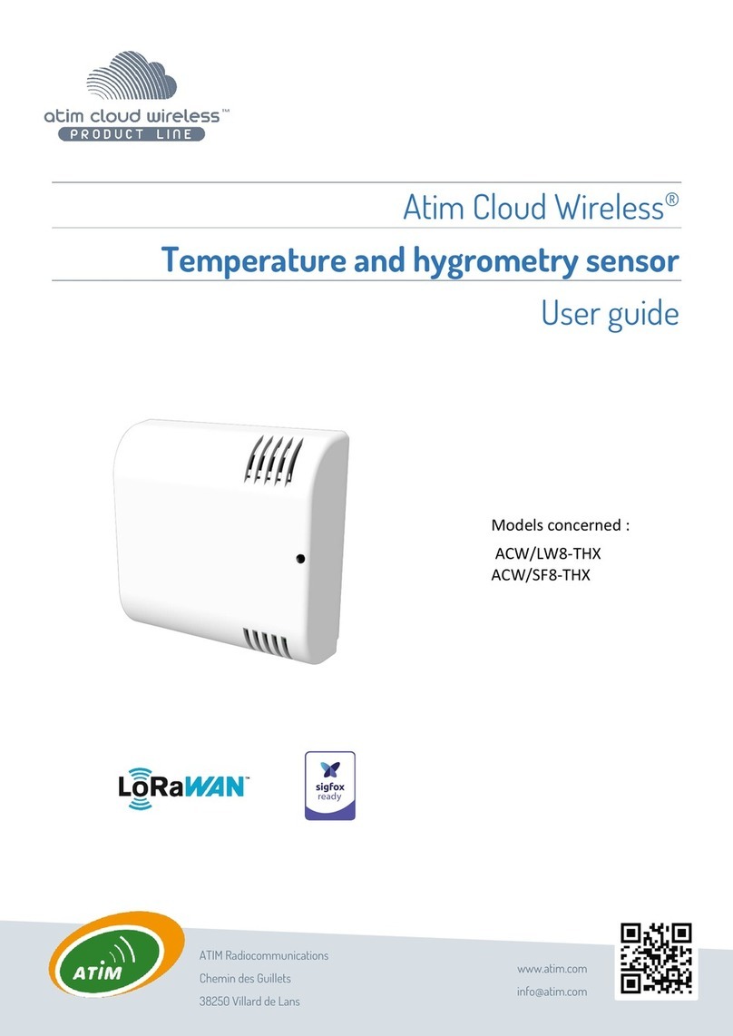
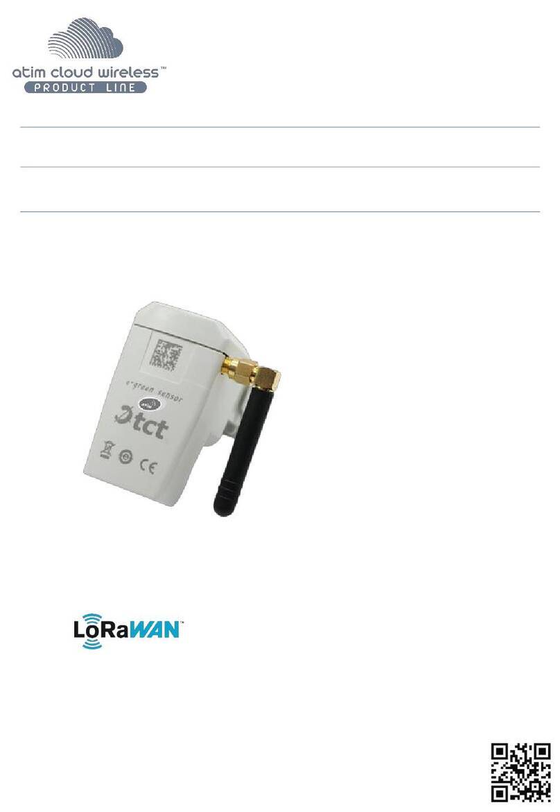
Atim Cloud Wireless ACW/SF8-WL-I User manual

Models concerned :
ACW/SF8-WL-I
ACW/LW8-WL-I
ACW/SF8-WL-O
ACW/LW8-WL-O
Atim Cloud Wireless®
Leak detection
User Guide

1
ATIM_ACW-WLL_UG_EN_V1.9
TABLE OF CONTENTS
Version history of this document ......................................................................................................................................3
Disclaimer..........................................................................................................................................................................3
Trademarks and copyrights...............................................................................................................................................3
Declaration of conformity .................................................................................................................................................4
Environmental recommendations.....................................................................................................................................4
Explosive atmosphere 4
Environment 4
Radio 5
Technical specifications..................................................................................................................................................... 6
a. Strengths 6
b. Technical specifications 7
Water leakage detection sensor 7
Housing..............................................................................................................................................................................8
a. Fastening 8
Identification 8
b. Magnet positioning 9
Available versions............................................................................................................................................................10
a. Cables 10
b. Connections and accessories 10
c. Summary of cable versions 11
Cable installation.............................................................................................................................................................12
a. Scheme 12
b. Examples 13
Operation ........................................................................................................................................................................14
a. Mode of operation 14
b. Putting the product into service 15
c. Sending a test frame 16
d. Deep sleep 16
e. Passivation of batteries 16
Operating mode 17
Life frame 18
Options 18
IP66 waterproof version 18

2
ATIM_ACW-WLL_UG_EN_V1.9
ACW Configurator ...........................................................................................................................................................19
Compatible configurator versions 19
Configuration...................................................................................................................................................................19
Alert/Error frame repeat (LORAWAN ONLY) 21
Frame format ..................................................................................................................................................................22
a. Quick start 22
Alert frames............................................................................................................................................................22
End of alerts frames................................................................................................................................................22
b. Full frame detail 22
Classic frame...........................................................................................................................................................23
Alert frame..............................................................................................................................................................24
Frame of life............................................................................................................................................................25
Test frame...............................................................................................................................................................25
Error frame .............................................................................................................................................................26
Troubleshooting ..............................................................................................................................................................29
Technical support............................................................................................................................................................29

3
ATIM_ACW-WLL_UG_EN_V1.9
Version history of this document
Version
Date
Description
Author
Software
version
concerned
0.1
06/04/2021
First draft
AJ
0.2
07/04/2021
Corrections & addenda
FR
1.0
15/04/2021
Draft version
FR
1.1
06/05/2021
Ancillary Additives
FR
1.2
30/07/2021
Patches & Additives
AJ
1.3
20/09/2021
Update after customer feedback
AJ
1.4
18/10/2021
Addition of English version + details
AJ
1.5
28/02/2022
Harmonization of references and cables
MD
1.0.3
1.6
14/03/2022
Clarifications
AJ
1.0.3
1.7
28/03/2022
Generic harmonization
MD
1.0.3
1.8
04/07/2022
Add repeat frame algortihm
YLB
1.0.4
1.9
04/08/2022
Indoor ft. Buzzer version added + Optical
sensing
AJ
1.0.4
Disclaimer
The information in this document is subject to change without notice and does not represent a commitment on the
part of ATIM radiocommunications. ATIM radiocommunications provides this document "as is" without warranty of
any kind, either expressed or implied, including, but not limited to, the implied warranties of merchantability or fitness
for a particular purpose. ATIM radiocommunications may make improvements and/or changes in this manual or in the
product(s) and/or program(s) described in this manual at any time.
Trademarks and copyrights
ATIM radiocommunications®, ACW ATIM Cloud Wireless®, ARM Advanced Radio Modem® are registered trademarks
of ATIM Sarl in France. Other trademarks mentioned in this document are the property of their respective owners.

4
ATIM_ACW-WLL_UG_EN_V1.9
Declaration of conformity
All ACW ATIM Cloud Wireless® products comply with the regulatory requirements of the R&TTE Directive 1999/5/EC
Article 3:
1 Safety (Article 3.1a of Directive 1999/5/EC)
NF EN60950-1 Ed. 2006/A1:2010/A11:2009/A12:2011 (health)
EN62479:2010 (power <20mW) or EN62311:2008 (power > 20mW)
2 Electromagnetic compatibility (Article 3.1b of Directive 1999/5/EC)
EN 301489-3 v1.4.1, EN 301489-1 V1.9.2
3 Efficient use of the radio frequency spectrum (Article 3.2 of Directive 1999/5/EC)
ETSI EN300 220-2 v2.4.1 and EN300 220-1 v2.4.1
Environmental recommendations
Explosive atmosphere
Except for ATEX products intended for this purpose, do not use ACW radio modems in the presence of flammable
gases and fumes. Use of the equipment in this environment constitutes a hazard.
Environment
Observe the storage and operating temperature ranges of the products. Failure to do so may result in operational
disturbance and even damage to the equipment. ACW products in IP65 weatherproof enclosures may be placed
outdoors but should never be immersed.
Follow the precautions and instructions listed below to ensure your safety and that of your environment and to
prevent damage to your equipment.

5
ATIM_ACW-WLL_UG_EN_V1.9
General Danger - If instructions are not followed, there is a risk of damage to equipment.
Electrical hazard - If the instructions are not followed, there is a risk of electric shock and personal injury.
Direct current symbol
WARNING: Do not install near any heat or moisture.
WARNING : for your safety, it is imperative that before any technical intervention on the equipment, it is
switched off and not connected to the mains.
WARNING: The safety provided by this product is only guaranteed for use as intended. Maintenance may only
be carried out by qualified personnel.
Disposal by users in private households within the European Union. This symbol on the product or its packaging
indicates that this product should not be disposed of with your other household waste. Instead, it is your
responsibility to dispose of your waste by bringing it to a designated collection point for the recycling of electrical
and electronic equipment. Separate collection and recycling of your waste at the time of disposal will help
conserve natural resources and ensure environmentally and human health friendly recycling. For more
information on the nearest recycling center to your home, contact the nearest city hall, the household waste
disposal service, or the store where you purchased the product.
Radio
The modems of the ACW series are part of the radiocommunication modems using the ISM (Industrial Scientific
Medical) bands which can be used freely (free of charge and without authorization) for industrial, scientific, and
medical applications.

6
ATIM_ACW-WLL_UG_EN_V1.9
Technical specifications
a. Strengths
Reference
WL-I
WL-O
Protection factor
IP30
(For the version with location option)
Alert
100 dB Buzzer + LED Flashes
LED flashing
Antenna
Built-in ¼ wave
Built-in ¼ wave
Cable
Water leak detection and/or location via cable
WL-I with Buzzer WL-O without Buzzer

7
ATIM_ACW-WLL_UG_EN_V1.9
b. Technical specifications
Dimensions
80 x 80 x 35 mm
Weight
100g
Antenna
Integrated (¼ wave)
Temperature
-20°C à +55°C (operation)
-40°C à +70°C (storage)
Housing and Mounting
ABS –Wall Mount
Power supply
1 Lithium battery pack 3,6V / 7,2Ah
Radio rate Sigfox
Sigfox : 100bps / LoRa : 300 to 10kbps
Frequency
865 –870 MHz (Europe Zone)
Power
25 mW (14 dBm)
Consumption
Sigfox
LoRaWAN
Tx mode
25 mA
50 mA
Standby mode
5 µA
1 µA
Rx mode
17 mA
22 mA
Water leakage detection sensor
Typical value
Location accuracy
+/- 1m
(For version with location option)
Reaction time
+/- 5s
Time needed for water to penetrate the cable (independent of the
reaction time of the whole product)

8
ATIM_ACW-WLL_UG_EN_V1.9
Housing
a. Fastening
The ACW-WL modem is mounted on a flat wall using the 4 mounting holes available at
each end of the box. For best results, it is recommended to install the box at a distance
from any metal object, e.g. avoid mounting it on a metal pole. As the antenna is integrated
in the box, it must be mounted vertically in the right direction on a vertical support or fixed
to a wall. The cable and/or the electrodes (2 screws) must always be downwards.
Identification
The product identifier is visible on the external label on the back of the product, inside on the electronic board and in
the status bar of the configuration software.
For LoRaWAN modems the communication keys are automatically given by the network (pairing by "Over The Air
Activation", or OTAA).
Each product of ATIM's ACW range has a QR Code label visible on the side of the product.
This QR code can be easily read with any 2D barcode reading application on smartphone.
Datamatrix:
Sigfox ID or LoRaWAN
DevEUI
Product serial number
Product reference:
Sigfox or LoRaWAN version
Sigfox or DevEUI
LoRaWAN ID
Product revision number
(hardware and firmware
technical status)
WL-O
ACW-WL-O label

9
ATIM_ACW-WLL_UG_EN_V1.9
The reading of this code indicates the following information:
ATIM|ACW/LW8-WL-O|C.0|190114|1|3.0|5.11|70B3D59BA0008C0A
Meaning
ATIM
ACW/LW8-WL-O
C.0
190114
1
3.0
5.11
70B3D59BA0008C0A
Manufacturer
name
Product number
Revision
version
Date of
manufacture
Manufacturin
g site
Version
hardware
Application
firmware
version
Sigfox ID
or
DevEUI LoRaWAN
Magnet positioning
The magnet mush be placed next to the QR Code on the left side of the device when changing modes.
When a magnet is mentioned in this guide, refer to this picture

10
ATIM_ACW-WLL_UG_EN_V1.9
Available versions
a. Cables
ATIM offers three cable versions to complement the ACW/WL:
The CAB-WL is sold by the meter and is coupled to the ACW/WL. It allows the detection of
water leakage.
The CAB-WLL is sold by the meter and is coupled to the ACW/WL. It allows the detection and
the localization of water leak.
The CAB-WLL-OIL is sold by the meter and is coupled to the ACW/WL. It allows the detection
of heating fuel.
The CAB-WLL-OPTO is an optical sensor which can detect the presence on a lot of different liquids
as water, oil (lubricants) and fuel. It only works on a fixed position
b. Connections and accessories
The CAB-WLL-LEAD is included by default with the ACW/WL. It connects the ACW/WL with the CAB-
WLL or CAB-WLL-OIL cable.
The CAB-WL-TERM, end of line connector, is not included by default with the ACW/WL. It
connects to the end of the CAB-WLL or CAB-WLL-OIL cable, thus closing the circuit.

11
ATIM_ACW-WLL_UG_EN_V1.9
The CAB-WL-CLIPS is an accessory for the ACW/WL to facilitate and simplify the fixing of the
sensing and/or locating cable.
- Dimension: 37 x 21 x 8 mm
- Fixing: to be glued or screwed (2 holes, ø4mm, distance between centers 22mm)
- Material: Flexible plastic + 2 stickers
c. Summary of cable versions
CAB-WL
Sensor cable for ACW/WL
[€/meter of cable]
CAB-WLL
Sensor cable for ACW/WL
with leakage location
[€/meter of cable]
CAB-WLL-OIL
Sensor cable for ACW/WL
(oil-fired heating)
[€/meter of cable]
CAB-WLL-OPTO
Optical liquid presence sensor
CAB-WLL-LEAD
Connection cable between ACW/WLL and
CAB-WLL-xx cables
CAB-WLL-TERM
End of line plug to be connected to the last
cable CAB-WLL-xx
CAB-WL-CLIPS
Clips for sensing cable
(100 pieces)

12
ATIM_ACW-WLL_UG_EN_V1.9
Cable installation
a. Scheme
NOTE
Jumpers are cable extensions that are insensitive to the presence of water.
WARNING
Never loop the cable over itself or create contact points with conductive surfaces, as there is a risk of false positives!

13
ATIM_ACW-WLL_UG_EN_V1.9
b. Examples
Cover an entire area
adapted to the global protection of
critical areas
Marginal area coverage
prevent leaks from entering the
environment or spreading
Covering key points
key protection against major
sources of leakage
Mounting clip
Adhesive cable
holder
Overhead piping
Grouped with a
floor stand
(susceptible to
interference)
Fixed with glue
(cables are easily
damaged)
Under the HVAC
downdraft (false
positive humidity)

14
ATIM_ACW-WLL_UG_EN_V1.9
Operation
a. Mode of operation
The new generation 2020 ACW (Atim Cloud Wireless®) products are all based on the same internal software
(Firmware) and bring interesting new features such as the selection and visualization of their operating mode. To know
the status of the product, you just must pass a magnet briefly (<2 sec) against the QRCODE label or on the Pepper
boxes against the small diamond, which causes the LED indicator of the corresponding color to light up:
→→→→
Deep sleep mode: When you take the product out of its packaging, it is by default in this deep sleep mode, which
optimizes the life of the batteries by avoiding their oxidation. The product does not transmit and waits patiently
for you to wake it up.
Network pairing mode: This mode is active as soon as the product leaves the deep sleep mode and allows the
pairing to a network (automatic in case of battery change).
Configuration mode: this mode is active 5 minutes after the exit of the deep sleep mode and authorizes the
configuration of the product in Bluetooth thanks to the PC configurator or to the mobile application ATIM. During
these 5 minutes messages are sent by radio every minute (5 "radio frames"), that allows you to check that the product
works well, for example after having placed it under a cast iron manhole. After this period, the product goes into
operation mode and the Bluetooth is deactivated (possibility to reactivate it via Downlink).
Operating mode: this is the default mode after the product start-up phase. In this mode, the module periodically
sends measurements according to the configuration applied (if the product has never been configured, the
factory configuration applies, see Factory Configuration).
Internal fault mode: This mode allows the normal operation of the module to be interrupted when a critical
event occurs. The nature of the event can be multiple:
•Battery empty (Battery voltage < 2.2V)
•Internal error of the radio module
•System error
The entry in this mode "Internal fault" is signaled by a RED flashing of the LED of the product
If the error does not come from the radio module, the product will send 3 radio frames every 24 hours containing the
error code(s) (see chapter Frame Format for error codes). In addition, the product will emit a warning light depending
on the nature of the event.
Once in this mode, the module must be restarted (by disconnecting and then reconnecting the battery, by Downlink
command or with the magnet) to regain normal operation.

15
ATIM_ACW-WLL_UG_EN_V1.9
b. Putting the product into service
Unless otherwise requested, ACW products are delivered with batteries connected and set to "deep sleep"
mode.
To place the product in its operating mode, hold a magnet against the QRCODE label for 6 seconds. During these six
seconds, the product's LED should blink WHITE and then GREEN at the end of the six seconds to indicate that the
product has been successfully switched on.
The ACW then enters the network pairing phase. During this phase, a FUSCHIA light signal with a fade effect
indicates that the search phase is in progress.
If the connection is successful, the product will emit a light signal indicating the quality of the network:
GREEN light signal: good network quality
•YELLOW light: average network quality
•ORANGE light: low network quality
•WHITE light: no information on network quality
The module will then enter its operating mode and start sending information to the network according to the
configuration.
NOTE
The LoRaWAN version, if it fails to connect, will go into simple sleep mode and make the next pairing attempt the next day and
every day until it successfully joins the network.
Special case
For a Sigfox product
•To have the information on the quality of the Sigfox network (GREEN, YELLOW or ORANGE light signal), it is
necessary to provide a Sigfox Downlink. It is this one which will allow to rule on the quality of the network.
The product emits at startup a test Uplink described in the chapter Classic frame (frame type 0x02). If a Sigfox
Downlink is provided, the information on the network quality will be sent back by the ACW (light signal). If no
Downlink is provided, the ACW will always display the WHITE light signal at the end.
•If a WHITE light signal is emitted by the product at the end of the 5min pairing phase and a Downlink has been
provisioned, it means that the Network is not accessible.
•If a WHITE light at the end of the 5min pairing phase is emitted by the product without a downlink having been
provisioned, this has no meaning as to the quality of the network. The network quality can be good or bad (or
non-existent).

16
ATIM_ACW-WLL_UG_EN_V1.9
For a LoRaWAN product
•In the default LoRAWAN Class A operating mode, (see Radio settings chapter), if at the end of the 5 minutes
pairing phase, no network has been reached, then the product goes into standby and will restart a 5-minute
pairing phase 24 hours later. So, if the product is placed in an area not yet covered by a network, the product
will join it when connectivity is possible. There is no need to intervene on the product for it to join the
network.
•In the LoRa/LoRAWAN Repeater Compatibility operating mode, (see chapter Radio parameters), if at the end
of the 5 minutes of the pairing phase, no network has been reached, then the product emits a WHITE light
signal and enters its nominal operating mode. Even if no network has been reached, it is assumed with this
mode that an ATIM LoRa/LoRAWAN repeater located nearby will be able to repeat the Local frames emitted
by the product in LoRAWAN frames on the network that the repeater has reached.
c. Sending a test frame
When the product is in its operating mode (and only in this mode), it is possible to send a test frame (which
avoids waiting for the next measurement frame) including a measurement sample.
To do this, simply move the magnet against the QRCODE label, which turns the LED GREEN and wait for it to go out
before removing the magnet. The successful sending of the test frame will be indicated by a CYAN light signal.
Just before sending, a leak detection is performed, and a value of this measurement is integrated in the frame. This
ensures that the cable or the electrodes are correctly installed. The test frames are identical to the alert frames. See
their structure in the "Alert frames" section.
In the case of a cable without the "Distance measurement" option (yellow and black cable). The measured value should
be close to zero.
d. Deep sleep
When transporting or storing the ACW-WL, it is best to place it in its deep sleep mode to limit unnecessary power
consumption.
From any operating mode (except fault mode), move a magnet against the QRCODE on the case for 6 seconds.
During these six seconds, the product's LED will flash the color corresponding to the operating mode and then
the end of the sequence will be indicated by a WHITE fade acknowledging that the product has been put to sleep.
The magnet can then be removed.
WARNING
When the operation is complete, press the button twice simultaneously to restore its main function. A white flash indicates that
the manipulation was successful.
e. Passivation of batteries
All new generation ACW products include a battery depassivation feature, which prevents battery oxidation during
prolonged deep sleep. This feature is automatically activated when the product enters its deep sleep mode. The
product will then be woken up once a day to start the battery depassivation sequence, and then the product will return
to deep sleep by itself.

17
ATIM_ACW-WLL_UG_EN_V1.9
Operating mode
The ACW-WL sensor periodically measures the electrical resistance between its 2 electrodes, or the 2 strands of its
cable to detect a possible presence of water at the time "t" and sends these data by radio on the Radio network (Sigfox
or LoRa) in case of positive result.
Start
Waiting x seconds
[check period]
Check presence of water
Sending of alert frame
+ audible alert if buzzer active, for x
seconds [alarm duration].
Measurement exceeds
threshold? [Threshold]
Waiting x seconds
[check period]
Check presence of water
Sending end of alert frame
Back to normal?
[Threshold]
no
yes
yes
no

18
ATIM_ACW-WLL_UG_EN_V1.9
See the "ACW Configurator" section to set each of the parameters shown in the diagram.
Life frame
These are issued either once a day or once every 4 days (configurable).
NOTE
By default, the period for sending life frames is set to once a day.
Options
A buzzer can be integrated in the sensor to emit an audible signal (100dB) in case of leak detection to signal an alert.
IP66 waterproof version
There is a specific version of the leak detector dedicated to the measurement of water leaks in the ground, especially
used for heating and cooling networks.
The sensor can then operate in areas where it is likely to be immersed. There is no buzzer of alarm on this version with
tropicalized card.
NOTE
Product number: ACW-WL-O (O for Outdoor)

19
ATIM_ACW-WLL_UG_EN_V1.9
ACW Configurator
Compatible configurator versions
The following application software
ACW Configurator Version
Sigfox : V1.0.4
LoRaWAN : V1.0.4
V5.3.0 or higher
Download and install the configuration software ''setupACW.exe'' at:
https://www.atim.com/en/products-configurator/
Configuration
The configuration is done via USB or Bluetooth. In the case of Bluetooth, you must restart the product, it should appear
in the list of products on the home page of the configurator. Double click on it to open the ACW-WL configuration
page.
1
2
3
4
5
6
7
8
This manual suits for next models
3
Table of contents
Other Atim Cloud Wireless Security Sensor manuals
Popular Security Sensor manuals by other brands

Leuze electronic
Leuze electronic MLC 300 Series manual

Nice
Nice MOONBUS MOFOB Instructions and warnings for installation and use

3M
3M DBI-SALA Nano-Lok XL Series instruction manual

DPM
DPM KY098YB manual

Suresafe
Suresafe VS-123 Mini manual

Winland
Winland Vehicle Alert Installation and operation instructions