manuals.online logo
Brands
  1. Home
  2. •
  3. Brands
  4. •
  5. ATIM
  6. •
  7. Measuring Instrument
  8. •
  9. ATIM ACW-DI2/868 User manual

ATIM ACW-DI2/868 User manual

Notice technique complète sur www.atim.com
FRQIG_ACW-DI
Page1/4
1. TECHNICAL FEATURES
Power supply : 2,7 –3,6Vcc
Active radio : 50mAmax
Digital input power : 5Vmax
Sleep mode consumption: 8µAtyp
Functioning temperature : -25°C –70°C
Radio power: 25mW 14dBm
Radio frequency: 868MHz
Range : 1 Km en extérieur
Minimum pulse time in counter mode : 50ms
Minimum pulse time in change of state: 250ms
Atim Cloud Wireless
Digital Input
Installation Guide
ACW-DI2/868
Configuration :
By USB with windows utility
Functioning mode :
Mirror mode
Master
Slave
www.atim.com
FRQIG_ACW-DI/868
Page2/4
2. INSTALLATION
It is necessary to open the case to get to the mini-USB port to
be able to configure the modem and to get to the terminal
block.
To do that, you have to insert the screwdriver into the slot
and tilt it downwards to lift the internal locking tab (cf.
photo). Then pull at the back of the casing to separate both
parts.
For optimal results, it is recommended to install the case
without environmental obstruction and to place it as high as
possible. For information, the antenna is integrated into the
case.
The case can be fixed on a flat wall or a tube following the
type of installation.
The orange button allows you to send a message to validate
the installation.
You can connect up to two digital inputs in counting mode or in alert
mode by level detection. The signal must be realized by one contact or a
push-pull output that doesn’t exceed 5V in high level. The ‘Break of cable
' input is for a fraud detection if the modem is taken away, this
information is periodically sent during the remote reading of the meter.
Type de câble à utiliser: maximum length 1 meter and recommended diameter 0,9mm, the thread on 9mm.
In the few seconds following the implementation of the power supply, a first radio transmission is made (visible by a
brief blue blinking of the LED) to allow you to verify functioning of the modem.
Input 1
GND
GND
Input 2
GND
Fente d’ouverture
www.atim.com
FRQIG_ACW-DI/868
Page3/4
3. CONFIGURATION
Download and install the configuration software
‘’setupACW.exe‘’ at this address :
http://www.atim.com/produit/atim-cloud-wireless-acw/
Connect the modem to the computer via the USB cable and
launch the software.
When you connect the modem, the software window
changes to allow you to reach the central features.
Automatically, the current configuration of the connected
modem is showed. You can then see this window.
The window is divided into different parts.
1 : Functioning mode: Two functioning modes are
available, slave and master.
In Slave mode it is your distant modem that is going to send a request to your ACW-DI.
In Master mode, the ACW-DI will send periodically (from 10min to 24h) or by the inputs change of state.
2 : Configuration des entrées : The ACW_DI module has 2 configurable inputs either for the detection of change
of state or to meter mode. Every input can be activated or not.
When the digital input is configured, this one detects a change of state on the chosen front.
Rising front
Downward front
Downward and Rising front
The signal must be realized by one contact (bounces are eliminated by soft) or a push-pull output where the
high level does not exceed 5V
When the input is configured in meter mode, this one counts the pulses that appear. The meter is incremented
on the rising front of the signal. The signal must be realized by one contact without bounce or a push-pull
output where the high level does not exceed 5V.
3 : Radio settings :
The radio channel has to be the same between your various equipment’s that want to communicate
together.
The modems address must corresponds to the address of your ACW-DI, every modem has to have a
different address.
The distant address is the address of the device with which you want to communicate.
4 : Statement period of the meter(s) : This menu allows you to configure the time between 2 sending’s of data.
This period is between 10min and 23h50min with a step of 10min. It is also the period in which will be made the
break of cable detection.
If you omit to define one the statement period fields. When you will click on Write a Invalide will appear next to
this one and a message will inform you about it and will indicate to you which field is at fault.
5 : Configuration : When you have finished, just click on Write for the validation. After a few seconds a message
appears next to this one to inform you if the modem has been updated or has failed. Note : It is in this phase that
the modem is updated with the hour on your PC.
6 : Default : Allows you to reset previous values of the meters. After erasing the protected values, you have to
configure the ACW-DI module again.
Once the configuration is finished, do not leave the module connected by USB. This way of functioning
uses a lot of energy. When you remove the USB connection without disconnecting the power supply
the module returns automatically to normal functioning and a first radio transmission is made in 60s.
www.atim.com
FRQIG_ACW-DI/868
Page4/4
4. MODBUS TABLE
Modbus Address
Data
0x00 (0)
Reading digital inputs
b0: state input 1
b1: state input 2
0x40 (64)
Read and write input 1 counter (b31 à b16)
0x41 (65)
Read and write input 1 counter (b15 à b0)
0x42 (66)
Read and write input 1 counter 2 (b31 à b16)
0x43 (67)
Read and write input 1 counter 2 (b15 à b0)
Supported Modbus functions :
Function
Type
0x03 (3)
Reading of several registers
0x10 (16)
Writing of several registers
5. MODBUS MASTER FRAME FORMAT
Slave Id
1 octet
Modbus Slave ID
14
Code Function
1 octet
0x10 (Write multiple registers)
10
Start Address
2 octets
MSB = 0x40, LSB=Slave Id
40001
Quantity of registers
2 octets
Number of registers to write
0004
Bytes count
1 octet
Number of bytes to write
08
Counter 1 MSB-LSB
4 octets
Input 1 counter
00000012
Counter 2 MSB-LSB
4 octets
Input 2 counter
00000008
CRC
2 octets
Error control code
XXXX
SLAVE ID
FUNC
START ADDR
REG QTY
BYTES
COUNT
COUNTER 1
MSB
COUNTER 1
LSB
COUNTER 2
MSB
COUNTER 2
LSB
CRC

Other ATIM Measuring Instrument manuals

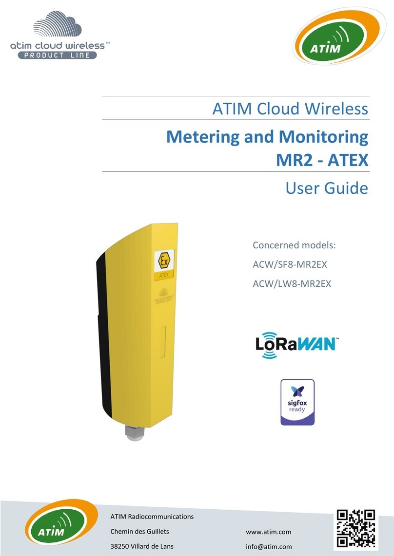
ATIM ACW/SF8-WL-I User manual

ATIM

ATIM ACW/SF8-WL-I User manual

ATIM ACW/SF8-MR2EX User manual

ATIM

ATIM ACW/SF8-MR2EX User manual

ATIM Cloud Wireless TH-I User manual

ATIM

ATIM Cloud Wireless TH-I User manual

ATIM Cloud Wireless ACW/SF8-LVL User manual

ATIM

ATIM Cloud Wireless ACW/SF8-LVL User manual

ATIM MR1 User manual

ATIM

ATIM MR1 User manual

ATIM Cloud Wireless TM P Series User manual

ATIM

ATIM Cloud Wireless TM P Series User manual

ATIM Cloud Wireless MR4 User manual

ATIM

ATIM Cloud Wireless MR4 User manual

ATIM Cloud Wireless ACW/LW8-THAQ User manual

ATIM

ATIM Cloud Wireless ACW/LW8-THAQ User manual

Popular Measuring Instrument manuals by other brands

Kobold HND-P215 operating instructions

Kobold

Kobold HND-P215 operating instructions

ELEKON BATLOGGER A Short manual

ELEKON

ELEKON BATLOGGER A Short manual

TESTO 540 Short manual

TESTO

TESTO 540 Short manual

ATD Tools ATD-3696 instructions

ATD Tools

ATD Tools ATD-3696 instructions

AERMEC AERWEB300 installation manual

AERMEC

AERMEC AERWEB300 installation manual

Pulsar Measurement Greyline AVFM 6.1 instruction manual

Pulsar Measurement

Pulsar Measurement Greyline AVFM 6.1 instruction manual

SEFRAM DAS240 user manual

SEFRAM

SEFRAM DAS240 user manual

Extech Instruments MA260 user guide

Extech Instruments

Extech Instruments MA260 user guide

Armstrong Monitoring Corporation AMC-CD2 instruction manual

Armstrong Monitoring Corporation

Armstrong Monitoring Corporation AMC-CD2 instruction manual

ITS Telecom DD890 manual

ITS Telecom

ITS Telecom DD890 manual

Hanna Instruments HI97738 instruction manual

Hanna Instruments

Hanna Instruments HI97738 instruction manual

Amprobe ACD-23SW user manual

Amprobe

Amprobe ACD-23SW user manual

Seca 274 manual

Seca

Seca 274 manual

emaux WT500PR user manual

emaux

emaux WT500PR user manual

Dwyer Instruments TAC-L Series Installation and operating instructions

Dwyer Instruments

Dwyer Instruments TAC-L Series Installation and operating instructions

Agilent Technologies 4263B Operation manual

Agilent Technologies

Agilent Technologies 4263B Operation manual

Teledyne T200U Manual addendum

Teledyne

Teledyne T200U Manual addendum

Agilent Technologies E8362C Installation note

Agilent Technologies

Agilent Technologies E8362C Installation note

manuals.online logo
manuals.online logoBrands
  • About & Mission
  • Contact us
  • Privacy Policy
  • Terms and Conditions

Copyright 2025 Manuals.Online. All Rights Reserved.