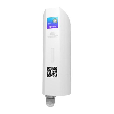
ATIM ACW/SF8-MR2EX User manual

[Tapez ici]
$
ATIM Radiocommunications
Chemin des Guillets
38250 Villard de Lans
www.atim.com
ATIM Cloud Wireless
Metering and Monitoring
MR2 - ATEX
User Guide
Concerned models:
ACW/SF8-MR2EX
ACW/LW8-MR2EX

1
ATIM_ACW-MR2-EX_UG_EN_V1.1
TABLE OF CONTENTS
Document version history....................................................................................................................... 2
Disclaimer................................................................................................................................................ 2
Trademarks and copyright....................................................................................................................... 2
Environmental recommendations........................................................................................................... 3
a) Explosive atmosphere ................................................................................................................. 3
b) Environment................................................................................................................................ 4
c) Radio............................................................................................................................................ 5
Product Identification.............................................................................................................................. 7
Technical specifications........................................................................................................................... 7
ACW-MR2-EX operating mode................................................................................................................ 8
a) “Meter reading” mode................................................................................................................ 8
b) “Dry contacts” mode................................................................................................................... 8
Footprint.................................................................................................................................................. 9
Fixing support........................................................................................................................................ 10
Implementation and positioning........................................................................................................... 11
Product restart ...................................................................................................................................... 12
Modem connection............................................................................................................................... 13
a) Connection to a pulse meter reading........................................................................................ 13
b) Connection to 2 meters............................................................................................................. 15
c) Gas metering wire ..................................................................................................................... 16
LED lights meaning ................................................................................................................................ 17
Configuration......................................................................................................................................... 18
a) Internal DIP switches configuration .......................................................................................... 18
b) Downlink frames configuration................................................................................................. 20
Sigfox –LoRaWAN frame format........................................................................................................... 23
Help ....................................................................................................................................................... 24
Technical support.................................................................................................................................. 24

2
ATIM_ACW-MR2-EX_UG_EN_V1.1
Document version history
Disclaimer
The information contained in this document is subject to change without warning and does not
represent a commitment on the part of ATIM radiocommunications. ATIM radiocommunications
provides this document ‘as-is’ with no warranty of any kind, express or implied, including but not
limited to implied warranties of merchantability or fitness for a particular purpose. ATIM
radiocommunications may make changes and/or improvements to this manual or to the product(s) or
program(s) described in this manual, at any time.
Trademarks and copyright
ATIM radiocommunications®, ACW ATIM Cloud Wireless® and ARM Advanced Radio Modem® are
registered trademarks of ATIM SARL in France. The other trademarks mentioned in this document are
the property of their respective owners.
Version
Date
Description
Author
0.2
06/04/2016
First version
YL
0.3
13/04/2016
Correction
YL
0.4
15/04/2016
Wire + ATEX
YL
0.5
09/05/2016
Ground
YL
0.6
19/05/2016
Distinction
YL
0.8
22/06/2016
LoRa reference added + join
YL
0.9
06/03/2017
Addition of SI
TDX
1.0
28/01/2020
Complete restructuring
ER

3
ATIM_ACW-MR2-EX_UG_EN_V1.1
Declaration of compliance
All ACW Atim Cloud Wireless® products comply with the regulatory requirements of the R&TTE
Directive (1999/5/EC), article 3:
1 SAFETY (Article 3.1a of the 1999/5/EC Directive)
NF EN60950-1 Ed. 2006/A1:2010/A11:2009/A12:2011 (health)
EN62479: 2010 (power <20mW) or EN62311:2008 (power > 20mW)
2 Electromagnetic compatibility (Article 3.1b of the 1999/5/EC Directive)
EN 301489-3 v1.4.1, EN 301489-1 V1.9.2
3 Efficient use of the radio frequency spectrum (Art.3.2 of the 1999/5/EC Directive)
ETSI EN300 220-2 v2.4.1 and EN300 220-1 v2.4.1
Environmental recommendations
a) Explosive atmosphere
The ACW-MR2-Ex complies with the standards EN 60079-0 and EN 60079-11 ("ic").
ACW-MR2-Ex can be used in an explosive atmosphere, Zone 2, gas group IIB, T4
temperature classification for a maximum ambient temperature of 55 ° C.
Corresponding ATEX certification is II 3 G, Ex ic IIB T4 Gc.
The ATEX certification of this ACW-MR2-EX product is only valid with the SATE
LS14500EX ATEX Certified Reference Battery.
Using another type of battery can cause an explosion. The housing must be screwed
to the equipment ground via the supplied bracket or a ground wire screwed to the
equipment (not supplied). ATIM disclaims any liability for failure to comply with these
procedures

4
ATIM_ACW-MR2-EX_UG_EN_V1.1
b) Environment
Respect the temperature ranges for storage and operation of all products. Failing to respect these
guidelines could disrupt device operation or damage the equipment. ACW products in IP65 water- and
dust-resistant housings may be placed outdoors, but must not, under any circumstances, be
submerged.
Follow the instructions and warnings provided below to ensure your own safety and that of the
environment and to protect your device from any potential damage.
This symbol appears on a product or its packaging to indicate that the product may not be discarded with
another household waste. Rather, it is your responsibility to dispose of this product by bringing it to a
designated collection point for the recycling of electrical and electronic devices. Collection and recycling
waste separately at the time you dispose of it helps to conserve natural resources and ensure a recycling
process that respects human health and the environment.
General hazard –Failure to follow the instructions presents a risk of equipment damage.
Electrical hazard –Failure to follow the instructions presents a risk of electrocution and physical injury.
Direct-current symbol
WARNING: do not install this equipment near any source of heat or any source of humidity.
WARNING: for your safety, it is essential that this equipment be switched off and disconnected from mains
power before carrying out any technical operation on it.
WARNING: the safe operation of this product is ensured only when it is operated in accordance with its
intended use. Maintenance may only be performed by qualified personnel.

5
ATIM_ACW-MR2-EX_UG_EN_V1.1
c) Radio
Modems in the ACW line are radio-communication modems that use the ISM (industrial, scientific and
medical) bands, which may be used freely (at no cost and with no authorisation required) for industrial,
scientific and medical applications.

6
ATIM_ACW-MR2-EX_UG_EN_V1.1
For a safe utilization
These devices must be connected to certified intrinsically safe equipment. Associations must be
compatible with intrinsic safety.
The electrical parameters of these devices must not exceed the values given below.
Approval: INTERTEK / ATEX / IECEx / Hazardous Locations
Intrinsic safety level II 3 G, Ex ic IIB T4 Gc
Spark risk assessment
Uo= 3.66V
Capacitive part: C≤20uF
Inductive Part: L≤12.3uH
Rated power: 150mW Imax = 900mA
Presence of an interface with external connected a TOR => use of resistances of blockings with 1k +
2.2k.
Signal output
Ui≤3.66 Volt
Li ≤1.3 mA
Li≈0 (negligible)
Signal equivalent to that of the dry contact
Cable length 5 m

7
ATIM_ACW-MR2-EX_UG_EN_V1.1
Product Identification
The product identifier is visible on the exterior label on the back of the device:
Technical specifications
Dimensions
177 x 55 x 55 mm
Antenna
Integrated (¼ wave)
Temperature
-20°C to +55°C (operating)
-40°C to +70°C (storage)
Mounts to
Wall
Shaft Sealing
IP 65
Battery
1 x battery Lithium A
Weight
160 g
Frequency
865 –870 MHz
Power
25 mW (14 dBm)
Rate
Sigfox: 100 bps
LoRaWan: 300 bit/s to 10 Kbit/s
Consumption
Sigfox
LoRaWan
Tx Mode
60 mA
76 mA
Rx Mode
35 mA
29 mA
Standby Mode
1,5 µA
2,5 µA
Active radio current power
50mA max for 6 seconds
Digital inputs tension
3,6V max
Product ID
Hardware version, Application
software/radio firmware number
Serial product number
Sigfox ID or DevEUI LoRaWAN
Datamatrix
Product reference:
Sigfox or LoRaWAN
version

8
ATIM_ACW-MR2-EX_UG_EN_V1.1
ACW-MR2-EX operating mode
This paragraph describes the operating mode of the ACW-MR2-EX, depending on the use case.
a) “Meter reading”mode
The ACW-MR2-EX sensor have 2 inputs which can be connected to dry pulse measurement contacts.
The ACW-MR2-EX device has 2 inputs which can be connected to dry contact pulse transmitters or to
an open collector for remote measurement.
Two operating modes are suggested:
•Standard meter reading
The device monitors both inputs. For these inputs, it increments the index for each pulse
received. Periodically (once per hour or once per day for example), it sends both indexes in the
same frame.
•Eco meter reading
The sensor does monitor only one input and it stores the index at a determined frequency
(every 10 minutes for example). It transmits a periodic frame with all 6 indexes (here, every
hour). In this operating mode, this is not possible to monitor in parallel 2 meters and only the
first input may be used.
ACW-MR devices count with a third input for anti-fraud, which allows to detect if the remote device is
connected. The device monitors this input every minute. In case of a state change, an alert frame with
the current state will be sent. This information is contained in every periodic reading frame.
The MR2 is delivered with a default configuration in Standard periodic reading with an index report
every 6 hours.
b) “Dry contacts”mode
ACW-MR Product line sensors inputs can also be linked to dry contacts outputs for change of states
detection. In this operating mode, if the device detects a change of state on at least one input, it will
transmit a frame containing the current state of both inputs. The bang-bang detection mode can be
set up among the following configurations:
•Inputs state checking every minute
•Contact closing detection
•Contact opening detection
•Contact closing or opening detection

9
ATIM_ACW-MR2-EX_UG_EN_V1.1
Footprint
Format and template of the fixing holes of the box
Opening of the ACW case
The box must be opened to access the module
configuration switches as well as the connection
terminal block.
To do this, insert the screwdriver in the slot and tilt
down to lift the inner tab (see photo opposite). Then
pull on the back side to separate the two parts of the
case.
Specific installation

10
ATIM_ACW-MR2-EX_UG_EN_V1.1
Fixing support
In order to meet the requirements of the safety standard, it is important to connect either the wall or
the product to the ground. A hole on the attachment has been provided for this use.
Fixing on a flat wall (provided):
Special condition for safe use
The end user will take all necessary precautions to install the
equipment in its final environment while maintaining the
equipotentiality of the earthing, via the support provided or by
a grounding cable screwed on the latter to the place indicated
in the installation instructions.
To prevent the occurrence of electrostatic discharge, the end
user should be careful not to clean the equipment with a dry
cloth. Favor the damp cloth.

11
ATIM_ACW-MR2-EX_UG_EN_V1.1
Implementation and positioning
Install the modem at a minimum height of 2m and not glued to the wall, ideally offset by at least
20cm the cables must not exceed 10m in length and must be shielded
For optimal results, it is advisable to place it in height and clear of any metallic obstacle in a radius of
1 meter if possible (see figures below). For information, the antenna is integrated into the box.
The magnet sensor on the right side emits a test frame to validate the installation on site.

12
ATIM_ACW-MR2-EX_UG_EN_V1.1
Product restart
A power failure is achievable by positioning a magnet near
a magnetic switch placed on the power supply of the
modem.
This operation can be useful to perform a restart (requires
positioning the magnet for about 30 seconds).

13
ATIM_ACW-MR2-EX_UG_EN_V1.1
Modem connection
ATIM warned the use only of
ATEX certified battery for the exact reference ACW-MR2Ex:
SAFT - LS14500Ex.
The polarity is indicated on the printed circuit board. The + pole is
oriented towards the terminal block, the pole - towards the antenna.
Start-up phases:
From 0 to 3 sec: bootloader.
From 3 sec to 8 sec: AT command configuration
From 8 sec to 10 sec: taking into account the configuration.
From 10 sec to 15 sec: emission of a frame of life
After 15 seconds: switch to standby
It is possible to connect:
•1 fast counter contact type contact: Counter 1
• 1 'wirecut' input of dry contact type. The monitoring of
this input is performed 1x / min.
• 1 slow counter contact type contact: Counter 2
a) Connection to a pulse meter reading
The amount of cables and their color depend on the pulse
emitter type installed on the meter. Please refer to the
emitter guide in order to verify the connection.
COUNTER 1
WIRECUT
COUNTER 2
COUNTER 2
WIRECUT
COUNTER 1

14
ATIM_ACW-MR2-EX_UG_EN_V1.1
2 cables connection (pulse emitter without anti-fraud output)
Please note that in particular cases, pulse and mass cables are undifferentiated.
Note
Disable the anti-fraud detection, connection the WIRECUT and GND inputs like shown on the diagram.
3 cables connection (pulse emitter with anti-fraud output)
Pulse cable
Ground cable
Pulse cable
Ground cable
Anti-fraud cable

15
ATIM_ACW-MR2-EX_UG_EN_V1.1
b) Connection to 2 meters
The amount of cables and their color depend on the pulse emitter type installed on the meter. Please
refer to the emitter guide in order to verify the connection.
2x2 cables Connection
Note
Disable the anti-fraud detection, connection the WIRECUT and GND inputs like shown on the diagram.
2x3 cables Connection
Pulse cable, meter 1
Ground cable, meter 1
Pulse cable, meter 2
Ground cable, meter 2
Pulse cable, meter 1
Ground cable, meter 1
Pulse cable, meter 2
Ground cable, meter 2
Anti-fraud cable, meter 1 or
Pulse cable, meter 2

16
ATIM_ACW-MR2-EX_UG_EN_V1.1
c) Gas metering wire
You can connect up to two logical counter inputs. The logic input accepts a volt free dry contact
or a voltage whose high level does not exceed 5Vcc (push-pull type). The 'Cable break' (or
'Fraud') input sends information if the read head or the link to your meter is removed,
periodically when the meter reading is issued.
The reading heads of the counters are polarized, the wire of brown color
corresponds to the mass and the white wire is the impulse input.
In counter mode, the index issued starts at 0 when first put into service. It is not possible to
implement an offset on the ACW modem, this difference is to be taken into account at the
reception (server). The counter is saved in memory when changing the battery. The maximum
value of the index is 4,294,967,295, then it starts again at 0.
Type of cable to be used (other than CAB / MTRGAZ1):
recommended maximum length 1 meter and recommended diameter 0,9mm, strip the wire to
9mm.
ATIM can provide a cable suitable for CAB / MTRGAZ1 reference gas meters with an M16 IP40
connector, having the following characteristics:
6 AWG shielded 6-wire cable with a length of 2 meters.
DIN socoker side view
You can connect the wires of the cable on the terminal block,
inside the box.
The wires are pre-wired according to the table below:

17
ATIM_ACW-MR2-EX_UG_EN_V1.1
PIN
COLOUR
SIGNAL
1
Brown
Oversight +
2
White
GND - Oversight
3
Grey
Metering 2 +
4
Blue
Metering 1 +
5
Yellow
GND - Metering 2
6
Green
GND - Metering 1
LED lights meaning
The red status indicator lights when the product is powered. After a few seconds, the green LED
flashes, which means that the modem is sending its data to the network.
With each new data transmission, the led flashes briefly.

18
ATIM_ACW-MR2-EX_UG_EN_V1.1
Configuration
The configuration can be realized locally thanks to internal switches, or remotely through downlink
frames. By default, the product uses the switch configuration until a downlink frames configuration is
not done.
If a downlink configuration is applied, throughout the next restart, this setting will be used.
a) Internal DIP switches configuration
The configuration is read at the starting of the device. The following table lists the different operating
modes that can be set up.
•Standard reading mode: periodic reading of both meter inputs (even if one unique input is
used) with a systematic data emission.
•Change of state detection mode: state emission of both inputs when a change if state on at
least one input is detected.
•ECO reading mode: periodic reading of meter 1 every X minute, with an emission every 6
readings.

19
ATIM_ACW-MR2-EX_UG_EN_V1.1
ON
OFF
STANDARD
METER
READING
MODE
Radio emission period (METER READING frame): 10 min
Radio emission period (METER READING frame): 30 min
Radio emission period (METER READING frame): 1 h
Radio emission period (METER READING frame): 3 h
Radio emission period (METER READING frame): 6 h
Radio emission period (METER READING frame): 12 h
Radio emission period (METER READING frame): 24 h
Radio emission period (METER READING frame): 48 h
CHANGE OF
STATE
DETECTION
MODE
Inputs state checking every minute.
Radio Emission is detection of change of state
(TRIGGER frame if a contact changes).
Radio emission on falling edge
(TRIGGER frame at the contact closing).
Radio emission on rising edge
(TRIGGER frame at the contact opening).
Radio emission on rising and falling edges
(TRIGGER frame at the contact change of state).
ECO METER
READING
MODE
Radio emission period (METER MULTI-READING frame): 1 h
1 Delta / 10min
Radio emission period (METER MULTI-READING frame): 3 h
1 Delta / 30min
Radio emission period (METER MULTI-READING frame): 6 h
1 Delta / 60min
NC
1
2
3
4
1
2
3
4
1
2
3
4
1
2
3
4
1
2
3
4
1
2
3
4
1
2
3
4
1
2
3
4
1
2
3
4
1
2
3
4
1
2
3
4
1
2
3
4
1
2
3
4
1
2
3
4
1
2
3
4
1
2
3
4
This manual suits for next models
1
Table of contents
Other ATIM Measuring Instrument manuals

ATIM
ATIM ACW/SF8-WL-I User manual

ATIM
ATIM ACW-DI2/868 User manual

ATIM
ATIM Cloud Wireless ACW/SF8-LVL User manual

ATIM
ATIM Cloud Wireless TH-I User manual

ATIM
ATIM MR1 User manual

ATIM
ATIM Cloud Wireless TM P Series User manual

ATIM
ATIM Cloud Wireless MR4 User manual

ATIM
ATIM Cloud Wireless ACW/LW8-THAQ User manual
Popular Measuring Instrument manuals by other brands

Arca Flow
Arca Flow Weka VLI EconomyLine 6 Installation and operating manual

WAVECONTROL
WAVECONTROL SMP2 user manual

PIETRO FIORENTINI
PIETRO FIORENTINI SSM-ICON 250 manual

Metabo
Metabo RF 60 operating instructions

Electronic Control Concepts
Electronic Control Concepts 890 instruction manual

Cirrus
Cirrus CK675 user manual