ATIM MR1 User manual

ATIM Radiocommunications
Chemin des Guillets
38250 Villard-de-Lans, France
www.atim.com
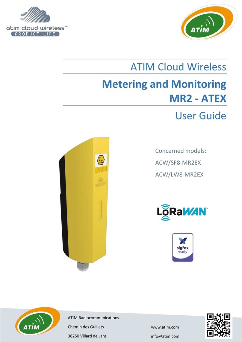
ATIM Cloud Wireless
Metering / State of dry contacts
MR1
User Guide
Concerned models:
ACW/SF8-MR1
ACW/LW8-MR1

1
ATIM_ACW-MR1_UG_EN_V1.6
TABLE OF CONTENTS
Disclaimer...........................................................................................................................................2
Trademarks and copyright ..................................................................................................................2
Declaration of compliance...................................................................................................................3
Environmental recommendations .......................................................................................................3
a. Explosive environment ................................................................................................................................... 3
b. Environment .................................................................................................................................................. 3
c. Radio.............................................................................................................................................................. 4
Prelude...............................................................................................................................................5
ACW-MR product line.........................................................................................................................5
Installation of the OPTO cable ............................................................................................................6
a. Description of pieces ...................................................................................................................................... 6
b. Procedure ...................................................................................................................................................... 6
Product identification.........................................................................................................................7
Technical features ..............................................................................................................................8
Operation...........................................................................................................................................9
a. Input 1: pulse counter .................................................................................................................................... 9
b. Output copy of the pulse in Mirror mode........................................................................................................ 9
c. Input 2: dry contact –detection of change of state ......................................................................................... 9
d. Input Optical head.......................................................................................................................................... 9
Installation .......................................................................................................................................10
Wiring of the terminal block .............................................................................................................11
Commissioning.................................................................................................................................12
Configuration ...................................................................................................................................13
Format of Sigfox –LoRaWAN frame..................................................................................................15
Technical support .............................................................................................................................16
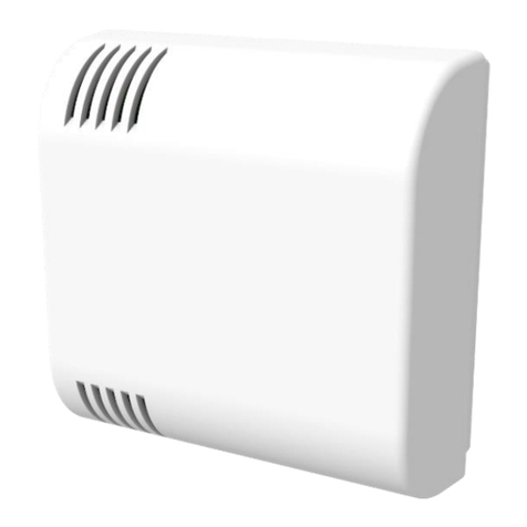
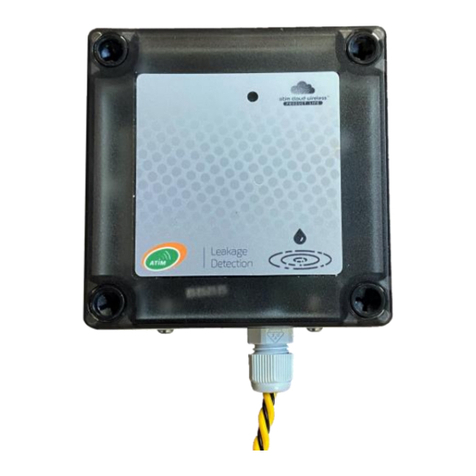
2
ATIM_ACW-MR1_UG_EN_V1.6
This user guide is applicable for the below references
Document version history
Version
Date
Description
Author
1.0
12/05/21
Document creation
FR
1.1
06/10/2021
Additions of complementary information
AJ
1.2
15/10/2021
Corrections
FR
1.3
11/04/2022
Software version vs functionalities checkup
JML
1.4
12/04/2022
Update of default parameters
FR
1.5
14/04/2022
Addition of the mounting instruction OPTO
AJ
1.6
20/04/2022
Additions of complementary information
JML
Disclaimer
The information in this document is subject to change without notice and does not represent a commitment on the
part of ATIM radiocommunications. ATIM radiocommunications provides this document "as is" without warranty of
any kind, either expressed or implied, including, but not limited to, the implied warranties of merchantability or fitness
for a particular purpose. ATIM radiocommunications may make improvements and/or changes in this manual or in
the product(s) and/or program(s) described in this manual at any time.
Trademarks and copyright
ATIM radiocommunications®, ACW ATIM Cloud Wireless®, ARM Advanced Radio Modem® are registered trademarks
of ATIM Sarl in France. Other trademarks mentioned in this document are the property of their respective owners.
Product references
Product version (visible on
the product label)
ACW/LW8-MR1
ACW/SF8-MR1

3
ATIM_ACW-MR1_UG_EN_V1.6
Declaration of compliance
All ACW Atim Cloud Wireless® products comply with the regulatory requirements of the R&TTE Directive 1999/5/EC
Article 3:
1 SAFETY (Article 3.1a of the 1999/5/EC Directive)
NF EN60950-1 Ed. 2006/A1:2010/A11:2009/A12:2011 (health)
EN62479: 2010 (power <20mW) or EN62311:2008 (power > 20mW)
2 Electromagnetic compatibilities (Article 3.1b of the 1999/5/EC Directive)
EN 301489-3 v1.4.1, EN 301489-1 V1.9.2
3 Efficient use of the radio frequency spectrum (Art.3.2 of the 1999/5/EC Directive)
ETSI EN300 220-2 v2.4.1 and EN300 220-1 v2.4.1
Environmental recommendations
a. Explosive environment
Except for ATIM's ATEX certified products (Example ACW-MR2-EX) intended for this use, do not use ACW radio
modems in the presence of flammable gases and fumes. The use of the equipment in this environment constitutes a
danger!
b. Environment
Observe the storage and operating temperature ranges of the products. Failure to do so may result in operational
disturbance and even damage to the equipment. ACW products in IP65 waterproof enclosures can be placed outdoors
but must not be immersed in water.
Follow the precautions and instructions listed below to ensure your safety and that of your environment and to
prevent damage to your device.

4
ATIM_ACW-MR1_UG_EN_V1.6
Waste disposal by users in private households within the European Union. This symbol appears on a product or
its packaging to indicate that the product may not be discarded with other household waste. Rather, it is your
responsibility to dispose of this product by bringing it to a designated collection point for the recycling of
electrical and electronic devices. Collection and recycling waste separately at the time you dispose of it helps
to conserve natural resources and ensure a recycling process that respects human health and the environment.
For more information on the recycling center closest to your home, contact your closest local government office,
your local waste management service, or the business from which you purchased the product.
c. Radio
The modems of the ACW series are part of the radiocommunication modems using the ISM (Industrial Scientific
Medical) bands which can be used freely (free of charge and without authorization) for industrial, scientific, and
medical applications.
General hazard –Failure to follow the instructions presents a risk of equipment damage.
Electrical hazard –Failure to follow the instructions presents a risk of electrocution and physical injury.
WARNING: do not install this equipment near any source of heat or any source of humidity.
WARNING: for your safety, it is essential that this equipment be switched off and disconnected from mains
power before carrying out any technical operation on it.
WARNING: the safe operation of this product is ensured only when it is operated in accordance with its
intended use. Maintenance may only be performed by qualified personnel.

5
ATIM_ACW-MR1_UG_EN_V1.6
Prelude
This guide describes the functionalities of the products of the ATIM ACW-MR range. It explains the operating,
configuration, and installation modes of the products according to the different use cases.
ACW-MR product line
The ACW-MR range includes several types of radio equipment for pulse counting, change of state detection and fraud
detection, each intended for different uses.
All products in the range are available in LoRaWAN and Sigfox versions and are delivered with removable batteries.
They are configurable via internal switches and by sending Downlink messages from the network (only in LoRaWAN
version).
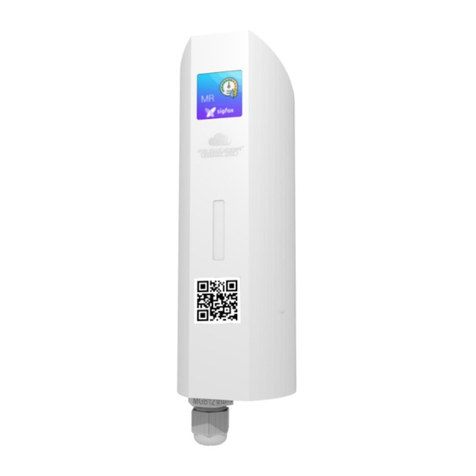
ACW-MR1
The ACW-MR1 is a device used for the remote reading of meters (gas, water, electricity, rain gauge...)
or for the remote detection of equipment status changes (e.g.: start/stop of equipment, opening/closing
of a door, a skydome, etc...).
For remote meter reading (Smart Metering), the ACW-MR1 must be connected to a pulse meter. If your
meter is not equipped with pulse outputs, many compatible pulse headers are available on the market.
In addition to its counting input, the ACW-MR1 is equipped with a dry contact input allowing to trigger
transmissions in case of change of state. This input can be used as a fraud detection in case of cable
cut.
The ACW-MR1 comes with a pack of 2 removable Lithium Ion 3.6V batteries, with a total capacity of
7.2Ah.
CAPT-OPTO
An optical head accessory is available for the ACW-MR1:
-a light guide to be clipped with a suction cup on any
electrical equipment equipped with an LED.

6
ATIM_ACW-MR1_UG_EN_V1.6
Installation of the OPTO cable
a. Description of pieces
b. Procedure
Fix the washer (F) on the location where the survey is to be carried out, so that the light
signal passes through the middle in the hole. It is important to clean the area and dry it to
ensure a reliable grip in the long term.
Position the part (E) on the washer so that the light signal is visible through the hole that
goes right through it. Alignment is essential.
Mount the cable (C) in the MR1 housing (A), lock the assembly by tightening the nut (B).
Finally, pass the clamping sleeve over the cable (C), place the other end of the cable at the bottom of the sleeve (E)
and clip parts (D) & (E) together to exert strong pressure against the adhesive washer (F).
MR1 casing
Nut Tightening Stuffing box
Cable
Clamping sleeve
Fixing sleeve
Adhesive washer
B
A
C
D
E
F

7
ATIM_ACW-MR1_UG_EN_V1.6
Product identification
The sensor ID is visible on the product label on the outside as well as inside the housing next to the batteries.
Product ID
Product revision number
(hardware and firmware
technical status)
Product serial number
Datamatrix: Sigfox ID
or LoRaWAN DevEUI
Product reference:
Sigfox or LoRaWAN
version
MR1
ACW-MR1 label

8
ATIM_ACW-MR1_UG_EN_V1.6
Technical features
Dimensions
177 x 55 x 55 mm
Weight
160g
Antenna
Embedded (1/4 of wave)
Temperature
-20°C to +55°C (operation)
-40°C to +70°C (storage)
Mounting
Wall, mast, DIN rail
Power Supply
1 pack of 2 batteries, equivalent to 7.2 Ah
Frequency
865 –870 MHz
Power
25 mW (14 dBm)
Rate
Sigfox: 100 bps
LoRaWAN: 300 bit/s to 10 Kbit/s
Consumption (24V)
Sigfox
LoRaWAN
Tx mode (max)
25 mA
50 mA
Rx mode (max)
17 mA
22 mA
Standby mode
2 μA
2μA
Power supply current (radio active)
50 m max for 6 seconds
Digital input tension
3,6 Vmax

9
ATIM_ACW-MR1_UG_EN_V1.6
Operation
a. Input 1: pulse counter
The ACW-MR1 has a metering input that can be connected to a dry contact or open collector type pulse emitter for
remote meter reading, and a dry contact input indicating an ON/OFF status.
Two modes of use are proposed:
1. Standard Meter reading
The sensor increments an index with each received pulse. Periodically (e.g. once an hour or once a day), it
transmits the index to the radio network.
2. Eco Meter Reading
The sensor increments an index with each received pulse. Periodically (for example every 10 minutes), it
memorizes the value of the index. When it has stored 6 values, it transmits them in a single frame to the radio
network.
NOTE
The index value is regularly saved in non-volatile memory to not being lost in case of power loss (for example when batteries
are empty). However, when a power loss is happening, the pulses received during the previous 10 minutes may be lost (in
addition to the pulses received during the power loss).
b. Output copy of the pulse in Mirror mode
The ACW-MR1 is equipped with an output to copy the pulse input. This makes it possible to be easily inserted
in an existing installation where there is already a pulse transmitter. In this case, the ACW-MR1 is inserted between
the meter and the pulse emitter.
The output terminals are called OUT1- and OUT1+ (galvanically isolated MOSFET dry contact).
c. Input 2: dry contact –detection of change of state
This input can be connected to a dry contact for change of state detection, in on-off mode. By default, if the sensor
detects a change of state on this input, it transmits an alert frame.
d. Input Optical head
The card is equipped with a phototransistor that detects the light pulses from the optical fiber if it is connected to
the cable gland (ACW-MR1/OPTO mode).

10
ATIM_ACW-MR1_UG_EN_V1.6
Installation
It is advisable to open the box to access the terminal block. To do this, insert the
screwdriver into the slot and tilt it downwards to lift the internal tab (see photo
opposite).
Then pull on the back side to separate the two parts of the case.
For best results, it is recommended to install the box without environmental
obstruction and to place it at a minimum height of 1m50.
It must be mounted on a vertical support or fixed to a wall (especially not on a
metal post!).
The box is fixed on a flat wall or a tube according to the type of installation
desired.
The cable should not exceed 10m in length and should be shielded.
NOTE
The antenna is integrated in the housing which must be installed vertically with the cable gland facing downwards.
1,50m

11
ATIM_ACW-MR1_UG_EN_V1.6
Wiring of the terminal block
You will find below the order of the inputs / outputs on the terminal block:
•CPT1: Meter Input,
•IN2: Dry Contact Input,
•OUT: Output, input image CPT,
•NC: Unused on this device. Do not wire.
CPT1-
CPT1+
IN2-
IN2+
OUT1-
OUT1+
NC
NC

12
ATIM_ACW-MR1_UG_EN_V1.6
Commissioning
The product is delivered in standby mode where it sends only the life frames.
To activate the product, press the push button for 2 seconds; the LED should blink 3 times to
indicate the switch to operating mode.
You can also pass a magnet over the diamond (area indicated on the red circle).
It is also possible to activate the product remotely by downlink (see the section Configuration).
NOTE
Approaching the magnet is equivalent to pressing the push button.
Test frame emission
When the product is in its operating mode, it is possible at any time to send a test frame. To do this, you must press
the push button briefly (less than 2 seconds) or pass the magnet briefly.
Periodic frames
This period of readinand transmission is configurable by the user, with a minimum of 10 minutes.
NOTE
By default, this period is set to every hour.
Keep alive frames
The period of the life frames is configurable by the user, with a minimum of 10 minutes.
NOTE
By default, the period for sending life frames is set to once a day.

13
ATIM_ACW-MR1_UG_EN_V1.6
Configuration
There is no USB or Bluetooth connector on this product. The configuration is done at the factory and can only be
changed via Downlink, i.e., from the customer's platform.
•In LoRaWAN, downlinks can be received by the product after each frame sending.
•In Sigfox, they can be received only when sending life frames.
The Downlink configuration frames are explained below, depending on the setting you wish to change.
Frequency of emission of the keep alive frame
Parameter code (1 byte)
Parameter value (1 byte)
0x03
The possible values are:
0x04 = every 10 minutes
0x05 = every hour
0x0A = every 2 hours
0x0B = every 4 hours
0x0C = every 8 hours
0x06 or 0x09 = once a day (factory setting)
0x0D = every 2 days
0x0E = every 3 days
0x0F = every 4 days
0x07 = every 7 days
0x08 = every 30 days
Operating mode
Parameter code (1 byte)
Parameter value (1 byte)
0x0A
The possible values are:
0x00 = standard counter mode with transmission every 10 minutes
0x01 = standard counter mode with transmission every 6 hours
0x02 = standard counter mode with transmission every hour (factory setting)
0x03 = standard counter mode with transmission every 3 hours
0x04 = standard counter mode with transmission every 30 minutes
0x05 = standard counter mode with transmission every 12 hours
0x06 = standard counter mode with transmission every 24 hours
0x07 = standard counter mode with transmission every 48 hours
0x09 = change of state detection mode with radio transmission on falling edge
0x0A = change of state detection mode with radio transmission on rising edge
0x0B = detection mode change of state with radio transmission on falling and rising edges
0x0C = ECO counter mode with reading every 10 minutes + transmission once an hour
0x0D = ECO counter mode with reading every 30 minutes + transmission every 3 hours
0x0E = ECO counter mode with reading once an hour + transmission every 6 hours

14
ATIM_ACW-MR1_UG_EN_V1.6
Internal resistance of inputs (CPT1+ and IN2+)
Parameter code (1 byte)
Parameter value (1 byte)
0x0B
The possible values are:
0x00 = high impedance (factory setting)
0x01 = pull-up
0x02 = pull-down
NOTE
The index of counter 1 can be changed to any value in the range of 0 to 4294967295.
Meter 1 settings
Parameter code (3 bytes)
Parameter value (4 bytes)
C1050Axxxxxxxx
For xxxxxxxx (in hexadecimal):
0x00000000
to
0xFFFFFFFF
EXAMPLE
If you want to set the index of counter 1 to 1000, you have to send in Downlink the command C1050A000003E8 (because 1000
= 3E8 in hexadecimal).
Bounce time
Parameter code (1 byte)
Parameter value (1 byte)
0x1E
Value in milliseconds, between 5 and 255.
Factory setting: 50ms
Product activation
Parameter code (2 bytes)
0x010B

15
ATIM_ACW-MR1_UG_EN_V1.6
Format of Sigfox –LoRaWAN frame
The data vary according to the type of frame transmitted and the operating mode (Meter, On/Off, MR1-Elec).
For example:
*Tref = time of issue
TYPE
DESCR.
FRAME FORMAT
octet 0
(dec)
octet 0
(hex)
octet 1
(hex)
octet 2
(hex)
octet 3
(hex)
octet 4
(hex)
octet 5
(hex)
octet 6
(hex)
octet 7
(hex)
octet 8
(hex)
octet 9
(hex)
octet 10
(hex)
octet
11
(hex)
KEEP ALIVE
Keep alive frame
1
01
Supply voltage
IDLE (mV)
Supply voltage
TX (mV)
64
METER
READING
Standard meter
frame
20
14
00
Meter index 1
0x00000000
TRIGGER
Change of state
detection frame
(Dry contacts)
9
09
00
XX
bit7
bit6
bit5
bit4
bit3
bit2
bit1
bit0
0
0
0
0
0
0
0
Logic
Level
IN2+
METER
MULTI-
READING
LoRaWAN
ECO mode meter
frame (meter 1 6
indexes 32 bits)
48
30
Index 5 (32bits)
(Tref-50min)
Index 4 (32bits)
(Tref-40min)
Index 3 (32bits)
(Tref-30min)
Index 2 (32bits)
(Tref-20min)
Index 1 (32bits)
(Tref-10min)
Index 0
(32bits)
(Tref)
Test frame
49
31
Index cpt 1
(32bits)
METER
MULTI-
READING
Sigfox
Trame
ECO mode meter
frame
(Meter 1
20 bits and
5 deltas 12 bits
concatenated)
57
39
Réf. Index
(20 bits)
(Tref)
Delta 1 (12bits)
(Tref-10min)
Delta 2 (12bits)
(Tref-20min)
Delta 3 (12bits)
(Tref-30min)
Delta 4 (12bits)
(Tref-40min)
Delta 5 (12bits)
(Tref-50min)
58
3A
Delta 1 (12bits)
(Tref-30min)
Delta 2 (12bits)
(Tref-60min)
Delta 3 (12bits)
(Tref-90min)
Delta 4 (12bits)
(Tref-120min)
Delta 5 (12bits)
(Tref-150min)
59
3B
Delta 1 (12bits)
(Tref-60min)
Delta 2 (12bits)
(Tref-120min)
Delta 3 (12bits)
(Tref-180min)
Delta 4 (12bits)
(Tref-240min)
Delta 5 (12bits)
(Tref-300min)
This manual suits for next models
2
Table of contents
Other ATIM Measuring Instrument manuals

ATIM
ATIM Cloud Wireless ACW/SF8-LVL User manual

ATIM
ATIM ACW/SF8-WL-I User manual

ATIM
ATIM ACW/SF8-MR2EX User manual

ATIM
ATIM Cloud Wireless ACW/LW8-THAQ User manual

ATIM
ATIM Cloud Wireless MR4 User manual

ATIM
ATIM Cloud Wireless TM P Series User manual

ATIM
ATIM Cloud Wireless TH-I User manual

ATIM
ATIM ACW-DI2/868 User manual
Popular Measuring Instrument manuals by other brands

dynasonics
dynasonics Badger Meter IS-6000 Doppler user manual

Raptor
Raptor R25668 instruction manual

ADWA
ADWA AD 630 user manual

Allen-Bradley
Allen-Bradley FactoryTalk Analytics for Devices quick start

sparklike
sparklike Laser Portable 2.0 Setup guide

Hanna Instruments
Hanna Instruments HI 991001 instruction manual