ATL Auto Wash 365 User manual

© ATL Agricultural Technology Limited: June 2019
Auto Wash 365 Manual
Version - 1.1
Date - June 2019
Part Number - 39-5715
Innovation In and
Out of Parlour

2 | Auto Wash 365 Manual | v1.1
© ATL Agricultural Technology Limited: June 2019
Innovation In and Out of Parlour
Index
Manual Version........................................................................................................... 4
About the Auto Wash 365................................................................................................ 5
Installing the Auto Wash 365,.......................................................................................... 7
Good Practice During the Installation............................................................................... 8
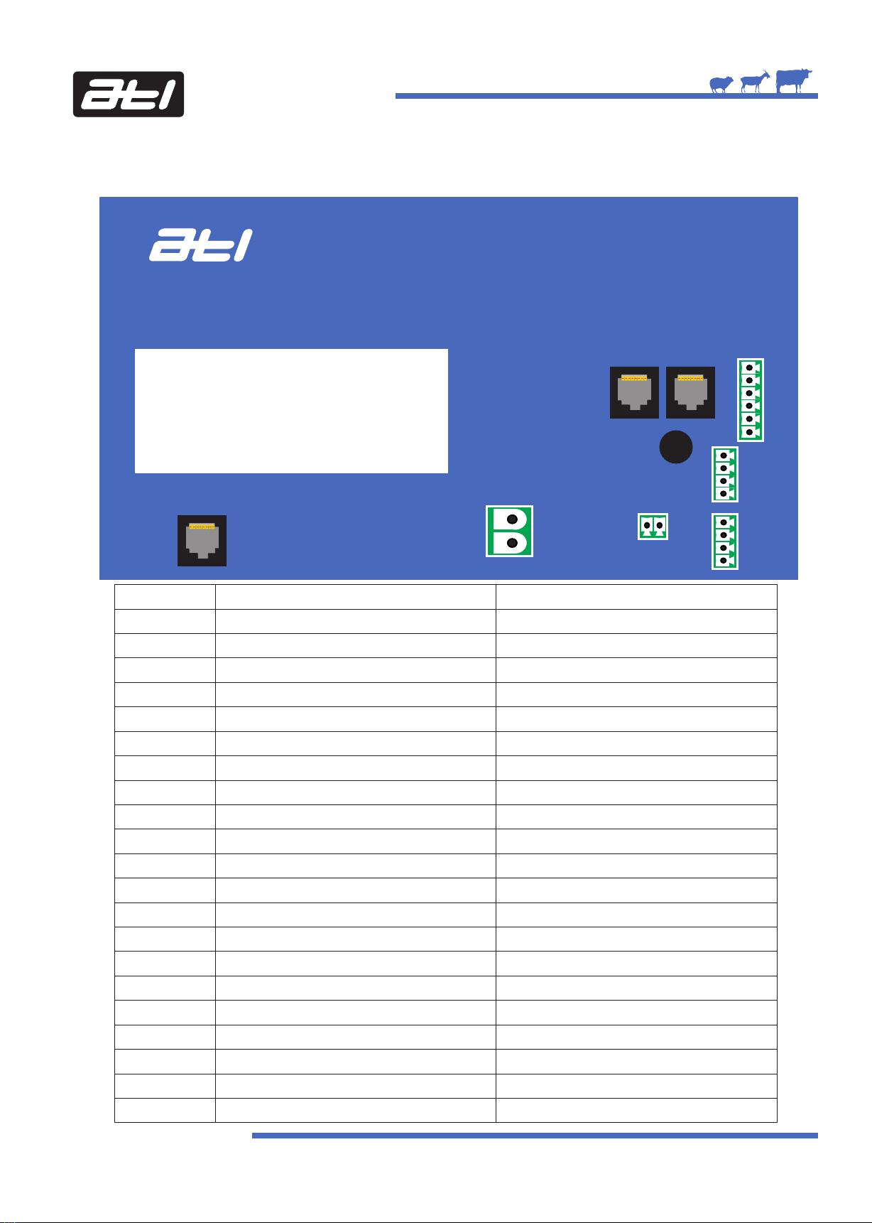
Auto Wash 365 Control PCB Wiring Connections................................................................. 9
Auto Wash 365 Input/Output PCB Wiring Connections......................................................... 10
Auto Wash Pump Box 800 Connections - Internal Hot and Cold Water Valves.......................... 12
Auto Wash 365 Layout Diagram.................................................................................... 13
Connecting the Auto Wash 365 to Vacuum Pumps.............................................................. 14
Connecting the Auto Wash 365 to the optional milk line lockout proximity sensor...................... 16
Setting Up the Auto Wash 365....................................................................................... 17
The Keypad............................................................................................................... 17
The Display................................................................................................................ 17
Entering Setup............................................................................................................ 18
The Key Buzzer Setting................................................................................................. 18
Setting the Time.......................................................................................................... 18
Setting the Date.......................................................................................................... 19
Editing Programs - See Page 31....................................................................................... 21
Editing Tasks - See Page 34............................................................................................ 21
Setting the Wash Trough Lock Out................................................................................... 21
Setting the Milk Tank Lock Out........................................................................................ 22
Setting the Vacuum Pump Type...................................................................................... 22
Calibration the Peristaltic Pumps - See Page 36................................................................... 22
Test Displays Diagnostic................................................................................................ 23
Test Keyboard Diagnostic.............................................................................................. 24
Input/Output (I/O) Printed Circuit Board (PCB) Diagnostics................................................. 25
Input/Output (I/O) Printed Circuit Board (PCB) Test Routines............................................... 27
Control Printed Circuit Board (PCB) Serial Number.............................................................. 29
Control Printed Circuit Board (PCB) Software Version.......................................................... 29
Restore Factory Settings............................................................................................... 30
Exit Setup.................................................................................................................. 31
Editing Programs......................................................................................................... 32

3 | Auto Wash 365 Manual | v1.1
© ATL Agricultural Technology Limited: June 2019
Innovation In and Out of Parlour
Index
Editing Tasks............................................................................................................... 35
Calibrating the Peristaltic Pumps..................................................................................... 37
Milking Mode............................................................................................................... 38
Washing Mode............................................................................................................ 39
Info Function.............................................................................................................. 41
Monthly / Six Monthly / Yearly Routine Maintenance............................................................ 44
Parlour Wash Down....................................................................................................... 44

4 | Auto Wash 365 Manual | v1.1
Innovation In and Out of Parlour
© ATL Agricultural Technology Limited: June 2019
Manual Versions
Version 1.0 - December 2015.........................First Version of Manual (Control v1.08 / IO Board v1.08)
Version 1.1 - June 2019......................................Updated manual for new wiring and proximity switch

5 | Auto Wash 365 Manual | v1.1
About the Auto Wash 365
The Auto Wash 365 from ATL is a simple and easy to use wash controller that washes the parlour
automatically after each milking. It provides more consistent and efficient cleaning using less chemical than
manual washing irrespective of the operator. The system is programmable and it’s versatility provides an
excellent wash to any type of small to medium size milking parlour.
Control Features
Programmable settings to be optimised for every milking parlour;
Large LED display showing washing status;
4 wash programs, including dedicated pre-milking key.
Pump Unit Features
Separate pump unit keeps electronics and chemicals apart;
Peristaltic pumps accurately dispenses chemicals at up to 800 millilitres per minute - up to a
maximum of 3 pumps;
Automatic chemical dispensing reduces operator handling of chemicals to a minimum;
3 different hot and cold water valve sizes - 10mm internal, 13mm internal and large bore external
water valves - choose at time of ordering.
Other Features
Temperature sensor for wash trough;
Pressure level sensor in wash trough;
Controls up to 2 vacuum pumps;
Vacuum operated 3 way diversion valve in return line for diverting to drain or wash trough;
12vDC output to turn milk pump on and off via relay/contactor;
12vDC output to turn air blast / wash slugger control on and off via relay/contactor;
12vDC output to turn master pulsation control on and off via relay/contactor;
Link to ATL milk pump control and air blast control to put them into wash, milk and idle via one button
press;
12vDC output for automatic drain valve included - vacuum or compressed air operated automatic
drain valve(s) optional;
12vDC output for wash safety switch included - wash safety switch optional;
12vDC output for milk safety switch included - milk safety switch optional;
12vDC output for wash trough drain valve - drain valve and solenoid not included;
Spare 12vDC output.
Benefits
Easy to use - just push a program button and the unit will automatically clean the milking parlour
for you;
Electronic system - optimise settings to suit any small or medium sized parlour;
Consistent cleaning control - temperature, chemical dosing and time are all automatically
controlled irrespective of the operator;
Automatic dosing of liquid detergents - maximises operator safety and prevents excessive use of
detergents;
Wash safety lock - prevents wash start up if milk delivery line connected to milk tank;
Vacuum pumps - staggered vacuum pump switch on.
Innovation In and Out of Parlour
© ATL Agricultural Technology Limited: June 2019

6 | Auto Wash 365 Manual | v1.1
Front Cover
Innovation In and Out of Parlour
© ATL Agricultural Technology Limited: June 2019
Auto Wash 365
ATL Agricultural Technology Ltd Units 1 & 2 Acorn Business Centre Oaks Drive Newmarket Suffolk CB8 7SY UK
Telephone: 0044 (0)1638 731212 Fax: 0044 (0)1638 731174 Website: www.atlagri.com E-mail: [email protected]
Innovation In and
Out of Parlour
Prog 1
Milk
Shift
Insert Delete
Prog 2 Prog 3
Enter
Setup
Info Stop
Reset
SkipPause
Pre
Milking
Clear
Back
Milking Key
Shift Function
- Pause
Shift Key
Pre-Milking
Wash Key
Shift Function
- Back
Wash Program
1 Key
Shift Function
- Skip
Info Key
Shift Function
- Clear
Stop Key
Shift Function
- Reset
Enter Key
Shift Function
- Setup
Wash Program
2 Key
Shift Function
- Insert
Wash Program
3 Key
Shift Function
- Delete
Down
Arrow Key
Up
Arrow Key

7 | Auto Wash 365 Manual | v1.1
Innovation In and Out of Parlour
Installing the Auto Wash 365 Control Unit and Pump Unit
The Auto Wash 365 system consists of a control unit, pump unit and power supply unit.
All of the units should be mounted on the wall to the side of the wash trough to avoid chemical gases and hot
water vapour damaging the unit.
© ATL Agricultural Technology Limited: June 2019

8 | Auto Wash 365 Manual | v1.1
Innovation In and Out of Parlour
Good Practice During the Installation
A separate mains supply and earth running directly from the consumer meter is essential.
Avoid routing the mains cable to the power supply close to other supplies especially those providing
intermittent current motors that are starting and stopping continually or high power heaters with
thermostatic control.
Terminate in a sealed, fused, double pole switched outlet fitted with a 13Amp (Type 1362) fuse or trip. A
3-pin ring main socket is not suitable in parlour conditions. All mains cabling must be contained in a firmly
secured durable conduit.
Power Supply: Siting
Fix the power supply to a wall or suitable brackets in a well ventilated area sufficiently high to avoid
physical contact or damage, leaving a gap of at least 250mm (10") between the top of the power supply
casing and the ceiling.
Position the power supply so that the output (low DC voltage) cables are as short as possible even if this
means extending the mains supply.
ATL Power Supplies: Output Voltages
ATL power supply outputs are factory set and should not be adjusted.
396 Watt 12vDC PSU 60 Watt 12vDC PSU
Input: 100 - 240vAC Input: 100 - 240vAC
Output: Nominal 12vDC Output: Nominal 12vDC
The 396 Watt 12vDC and 60 Watt 12vDC power supplies have a thermal cutout and overload protection
which removes power from the outputs in the event of an overload.
There are two indicators fitted to the base of the power supply casing; red indicates that the mains is
present and green that the output supply is available.
Control and Feeder Cables and Conduit
Cables must be kept as short as possible running directly from point to point. Cut out any excess cable
rather than leaving it coiled.
Wherever possible cables should be contained in a waterproof conduit using the correct csa cable
specified in the diagrams.
Entries must be made into the bottom of power supply or control casings but never into the
top. This will invalidate the warranty.
Strip existing cables back to bright copper before connection.
Keep multicore cables away from other cables especially those carrying mains or heavy currents. Cross
o
only at 90 where necessary and do not enclose in conduit with other cables.
© ATL Agricultural Technology Limited: June 2019

9 | Auto Wash 365 Manual | v1.1
Auto Wash 365 Control PCB Wiring Connections
The Auto Wash 365 Control PCB wiring connections are shown in the diagram and table below.
© ATL Agricultural Technology Limited: June 2019
Innovation In and Out of Parlour
Parlour Processor
2
3
Number
1
2
3
4
5
6
7
8
9
10
11
12
13
14
15
16
17
18
19
20
21
Connects To
Ethernet Cat5e - Input/Output PCB
Power In -12vDC
Power In +12vDC
RS485 Cat5e Connection
+ve RS485 Power
Data A
Data B
EOL Link
Screen
-ve RS485 Power
Unused
Unused
Unused
Unused
Unused
Unused
Unused
Unused
Unused
Unused
Cable Specification
Red Cat5e Cable
Unused
Unused
Yellow Cat5e Cable
Yellow Cat5e Cable
Unused
Twisted Pair - Red
Twisted Pair -Black
Only Connect When Instructed by ATL
Twisted Pair Screen
Unused
Unused
Unused
Unused
Unused
Unused
Unused
Unused
Unused
Unused
Unused
1
4 5
6
7
8
9
10
11
12
13
14
15
16
17
18
19
20 21
IMPORTANT - DO NOT INSTALL TWO
CABLES THROUGH 1 CABLE HOLE IN
THE 4 PORT GLAND. THIS WILL
INVALIDATE THE WARRANTY.

10 | Auto Wash 365 Manual | v1.1
Auto Wash 365 Input/Output PCB Wiring Connections
The Auto Wash 365 Input/Output PCB wiring connections are shown in the diagram and corresponding table
below.
© ATL Agricultural Technology Limited: June 2019
Innovation In and Out of Parlour
Plantwasher
Input/Output
Board
Number
1
2
3
4
5
6
7
8
9
10
11
12
13
14
15
16
Connects To
Temperature Probe Screen
Temperature Probe -ve
Temperature Probe +ve
Hot Water Valve +ve Common
Hot Water Valve -ve Switched Output
Cold Water Valve +ve Common
Cold Water Valve -ve Switched Output
Drain Valve +ve Common
Drain Water Valve -ve Switched Output
Divertor Valve +ve Common
Divertor Valve -ve Switched Output
Vac Pump 1 Start 12vDC +ve
Vac Pump 1 Start 12vDC -ve
Vac Pump 2 Start 12vDC +ve
Vac Pump 2 Start 12vDC -ve
Vac Pump Stop 12vDC +ve
Cable Specification
Screened Twisted Pair Provided
10 Way Cable Provided
1.5mm CSA
1.5mm CSA
10 Way Cable Provided
Use Appropriate Cable
49
30
31
32
33
1
2
34
5
6
7
8 10
9 11
12 14
13 15
16
17 18
19
20
21
22
23
26
27
28
29
24
25
37 35
36 34
41 39
40 38
45 43
44 42
47
46
48

11 | Auto Wash 365 Manual | v1.1
Auto Wash 365 Input/Output PCB Wiring Connections
Number
17
18
19
20
21
22
23
24
25
26
27
28
29
30
31
32
33
34
35
36
37
38
39
40
41
42
43
44
45
46
47
48
49
Connects To
Vac Pump Stop 12vDC -ve
+12vDC IN
-ve 12vDC IN
+12vDC OUT
-ve 12vDC OUT
+ve Peristaltic Pump Supply
-ve Peristaltic Pump Supply
+ve Peristaltic Pump 1 (Acid)
-ve Peristaltic Pump 1 (Acid)
+ve Peristaltic Pump 2 (Alkaline)
-ve Peristaltic Pump 2 (Alkaline)
+ve Peristaltic Pump 3 (Detergent)
-ve Peristaltic Pump 3 (Detgent)
Unused
Unused
-ve Peristaltic Pumps
Milk Tank Lockout Input
Milk Tank Lockout Common
Wash Trough Lockout Input
Wash Trough Lockout Common
Output 1 +ve Common
Output 1 -ve Switched
Auto Drain +ve Common
Auto Drain -ve Switched
Pulsation +ve Common
Pulsation -ve Switched
AirBlast +ve Common
AirBlast -ve Switched
Milk Pump +ve Common
Milk Pump -ve Switched
Wash Trough Level Input
Ethernet Cat5e - Parlour Processor
Cable Specification
Use Appropriate Cable
2.5mm CSA
2.5mm CSA
2.5mm CSA
2.5mm CSA
10 Way Cable Provided
–
–
10 Way Cable Provided
Use Appropriate Cable
10 Way Cable Provided
Use Appropriate Cable
Tubing Provided
Cat5e Cable
© ATL Agricultural Technology Limited: June 2019
Innovation In and Out of Parlour

12 | Auto Wash 365 Manual | v1.1
Innovation In and Out of Parlour
© ATL Agricultural Technology Limited: June 2019
Auto Wash Pump Box 800 Connections - Internal Hot and Cold Water Valves
The Auto Wash Pump Box connections are shown in the diagram below.
Acid Alkali Detergent
10 Way Cable from
Auto Wash 365 Control
Red - from
10 Way Cable
Brown
Blue - from
10 Way Cable
Red
Black
Black
Red Orange - from
10 Way Cable
Pink - from
10 Way Cable
Brown - from
10 Way Cable
Purple - from 10 Way Cable Grey - from
10 Way Cable White - from 10 Way Cable
Black - from
10 Way Cable
Green - from
10 Way Cable
Unused
Black
Optional 3rd Perisaltic Pump
Optional 2nd Solenoid Valve
Use Clips Provided
to Attach Pipes
to Pumps
Vacuum Pipe
In and Out
From Solenoid
Valves
Gland for 15mm
Pipe for Hot Water
Gland for 15mm
Pipe for Cold Water

13 | Auto Wash 365 Manual | v1.1
Auto Wash 365 Layout Diagram - Internal Hot and Cold Water Valves
Live
Neutral
Earth
60 Watt 12vDC
Power Supply
Auto Wash 365
_
+
+
+
© ATL Agricultural Technology Limited: June 2019
Innovation In and Out of Parlour
_
10 Way Cable
To Parlour
Wash Line
Hot Water IN
Cold Water IN
Wash Trough
Pump Box 800 Hot Water OUT
Cold Water OUT
Vacuum IN
3-Way Valve
Vacuum OUT
To 3-Way
Recirculation
and Drain
Valve
From Milk Pump
and Receiver
To Drain
Vacuum IN
Auto Drain
(Optional)
Vacuum OUT
Auto Drain
(Optional)
Acid Alkali Detergent
Temperature Sensor
Pressure Sensor for Water Level in Wash Trough
Recirculation
RS485 Data Cat5e Cable
to Milk Pump Control
Divertor
Valve

14 | Auto Wash 365 Manual | v1.1
Connecting the Auto Wash 365 to the Vacuum Pumps
Connecting from the Plantwasher Input/Output Printed Circuit Board (PCB)
Start 1-ve - White - Connect into connection number 13
Start 2 -ve - Green - Connect into connection number 15
Stop -ve - Red - Connect into connection number 17
Common + - Black - Connect into connection number 16
Connecting into the Vacuum Pump Starter Control Box
Innovation In and Out of Parlour
© ATL Agricultural Technology Limited: June 2019
Plantwasher
Input/Output
Board
12 14
13 15
16
17
Wire connects to
Vacuum Pump
Starter Control
Box
Start
1
Relay
Stop
1
Relay
Start
2
Relay
Stop
2
Relay
Common
Normally Open
Coil
Normally Closed
4 Core Cable
to Contactor
in Starter Box
for Vacuum
Pump 1
4 Core Cable to
Contactor in
Starter Box
For Vacuum
Pump 2
Green
Green
Yellow
Red
Yellow
Red
Blue Blue
Red
Green
White
Black
Red Red Red
Red
Black (1) from Black/White Pair
Black (2) from Black/Red Pair
From Auto
Wash 365
Control

15 | Auto Wash 365 Manual | v1.1
Connecting the Auto Wash 365 to the Vacuum Pumps Continued
Connecting to the Vacuum Motor Starter Box
Red, yellow, blue and green wires are from the Vacuum Pump Starter Control Box.
Warning: Contactor
Coil is 230v
Innovation In and Out of Parlour
© ATL Agricultural Technology Limited: June 2019
A13
B
A1
K1
A2
95
X BREAK HERE
95
14
L
N
STOP
(RED)
START
(GREEN)
96
14
13
A2
K1
RED
YELLOW
BLUE
GREEN
(Remove Black Loopwire)

16 | Auto Wash 365 Manual | v1.1
86
85
87a 30
87
Connecting the Auto Wash 365 to the Optional Milk Lock Proximity Sensor
Connecting from the Plantwasher Input/Output Printed Circuit Board (PCB)
+ve - Brown - Connect into connection number 20
-ve - Blue - Connect into connection number 21
Signal - Yellow (1) - Connect into connection number 37
Signal -Yellow (2) - Connect into connection number 36
Connecting into the Proximity Sensor
+ve - Brown - Connect into connection number 1
-ve - Blue - Connect into connection number 2
Signal-Green/Yellow - Connect into connection number 3
Plantwasher
Input/Output
Board
49
30
31
32
33
16
17 18
19
20
21
22
23
26
27
28
29
24
25
37 35
36 34
Innovation In and Out of Parlour
© ATL Agricultural Technology Limited: June 2019
Wire connects to
Proximity Sensor,
shown below
Proximity Sensor
3 Core Cable
from Auto
Wash
85
3
2
4
1

17 | Auto Wash 365 Manual | v1.1
Innovation In and Out of Parlour
© ATL Agricultural Technology Limited: June 2019
Setting up the Auto Wash 365
Before it can be used, the Auto Wash 365 must be setup. This is outlined in the following pages.
The Keypad
There are 11 keys on the keypad. 4 are for washing programs - Pre-Milking, Prog 1, Prog 2 and Prog 3 - the
Milk key is for milking mode, the Info key provides information on the wash, and the remaining keys are
Stop, Enter, Shift, Up and Down.
There a number of keys that are dual function with the use of the Shift key - these provide the programming
and user functions when a wash program is running. The other function of the key is shown in the grey box at
the top of the key. The keys which have dual function are Milk, Prog 1, Prog 2, Prog 3, Pre-Milking, Info, Stop
and Setup.
The keypad is constructed from a tough membrane overlaying individual key switches. This is a proven,
reliable construction which will last for many years provided it is cleaned only with warm soapy water and not
hosed down at high pressure.
The Display
The display has two areas. The Mode area shows the current mode - either Idle when neither milking or
washing, Milk when in Milking Mode or PRE, PG1, PG2 or PG3 when in Washing Mode. The Function area
shows where the control is in Wash Mode or displays the time in Milking or Idle Modes.
The Auto Wash 365 Control is very energy efficient; power saving was an important element of the design
criteria. If a key is not pressed for 30 minutes, the display will shut down but can be re-illuminated by
pressing any key.
IDLe 15--48--44
Mode Function Window
Prog 1
Milk
Shift
Insert Delete
Prog 2 Prog 3
Enter
Setup
Info Stop
Reset
SkipPause
Pre
Milking
Clear
Back

18 | Auto Wash 365 Manual | v1.1
Entering Setup
During the setup process, it is necessary to enter and modify data. Before this can be achieved, the Auto
Wash 365 Control has to be put into setup using this key sequence:
Press the Shift + Enter keys to enter setup.
After 2 seconds the key buzzer setting will be displayed.
The Key Buzzer Setting
This sets whether the key buzzer sounds when the keys are pressed. It is an ON/OFF setting. The factory
default is OFF.
Press the Enter key to toggle between ON or OFF.
Press the Down Arrow key to move onto the time setting.
Setting the Time
This sets the time on the control unit.
Press the Enter key to change the time.
The display will now show ‘SET HOUR HH’ with HH being the hour - HH will flash.
Press the Up or Down Arrow keys to change.
Innovation In and Out of Parlour
Time hh--mm--ss
Enter
Setup
key buzzer off
Enter
Setup
Enter
Setup
set hour hh
or
setup
© ATL Agricultural Technology Limited: June 2019
Shift
+

19 | Auto Wash 365 Manual | v1.1
Innovation In and Out of Parlour
© ATL Agricultural Technology Limited: June 2019
Setting the Time Continued
Press the Enter key to save or press Shift + Stop key to cancel.
If the Enter key is pressed, the display will now show ‘SET HOUR MM’ with MM being the minute - MM will
flash.
Press the Up or Down Arrow keys to change.
Press the Enter key to save or press Shift + Stop key to cancel.
Press the Enter key to toggle between ON or OFF.
Press the Down Arrow key to move onto the time setting.
Setting the Date
This sets the date on the control unit.
Press the Enter key to change the day of the month.
The display will now show ‘SET DAY DD’ with DD being the day of the month - DD will flash.
Press the Up or Down Arrow keys to change.
Press the Enter key to save or press Shift + Stop key to cancel.
If the Enter key is pressed, the display will now show ‘WDAY DDDDDDD’ with D being the day of the
week - this is needed so the control knows what day of the week it is.
Enter
Setup
Shift Stop
Reset
+
set hour MM
or
Enter
Setup
Shift Stop
Reset
+
Enter
Setup
set day dd
or
Enter
Setup
Shift Stop
Reset
+
Enter
Setup

20 | Auto Wash 365 Manual | v1.1
Innovation In and Out of Parlour
© ATL Agricultural Technology Limited: June 2019
Setting the Date Continued
Press the Up or Down Arrow keys to change.
Press the Enter key to save or press Shift + Stop key to cancel.
If the Enter key is pressed, the display will now show ‘SET MONTH MM’ with MM being the month - DD will
flash.
Press the Up or Down Arrow keys to change.
Press the Enter key to save or press Shift + Stop key to cancel.
If the Enter key is pressed, the display will now show ‘SET YEAR YY’ with YY being the month - YY will
flash.
Press the Up or Down Arrow keys to change.
Press the Enter key to save or press Shift + Stop key to cancel.
If the Enter key is pressed, the display will return to the setup menu.
Press the Down Arrow key to move onto edit programs.
or
Enter
Setup
Shift Stop
Reset
+
set MONTH MM
or
Enter
Setup
Shift Stop
Reset
+
set year yy
wday ddddddd
or
Enter
Setup
Shift Stop
Reset
+
Table of contents
Popular Farm Equipment manuals by other brands

Mizuho
Mizuho V Attachment Operator's manual

Amazone
Amazone Certos 4001-2TX operating manual

Meridian
Meridian TITAN SR2 Operator's manual

Checchi & Magli
Checchi & Magli BABY COMPACT Use and maintenance manual

GEA
GEA Lagoon Agitator instruction manual

Sukup
Sukup 5K Commercial Paddle Sweep Owner's installation & operations manual

Multiva
Multiva OPTIMA EVO 600 Operation and maintenance manual

Calmer
Calmer BT Chopper Upgrade Kit installation manual

Buhler
Buhler Swath Roller FK358 Operator and parts manual

enorossi
enorossi G4V-3P Use and maintenance manual

Ritchie
Ritchie EcoFount Series installation instructions

MASSEY FERGUSON
MASSEY FERGUSON MF 1316S Operator's manual