6
Any revisions must first be approved by the product designer. Version: 201909 Revision by: JST
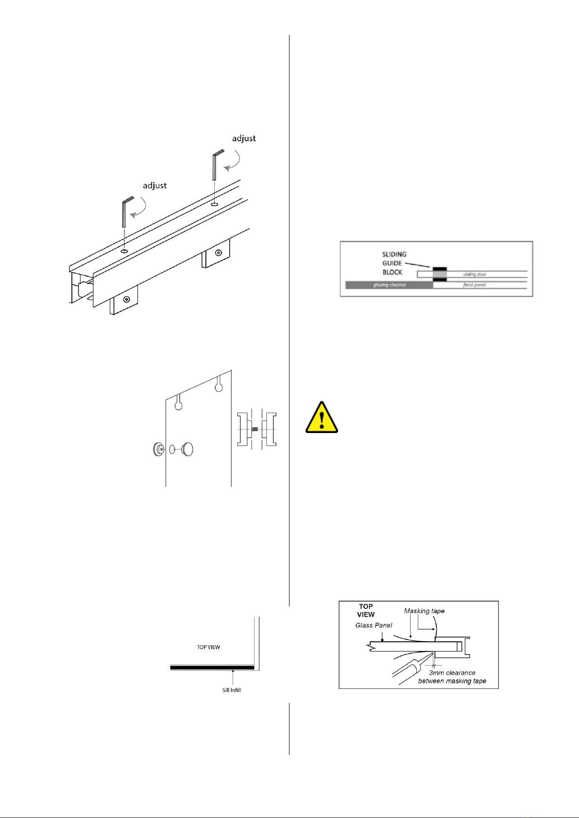
18. DOOR ALIGNMENT
Adjustment holes have been predrilled in the
top track. Door alignment can be achieved by
using 4mm hex key through the top track into
the top of the door hangers. Turn the key
anticlockwise to lift the door.
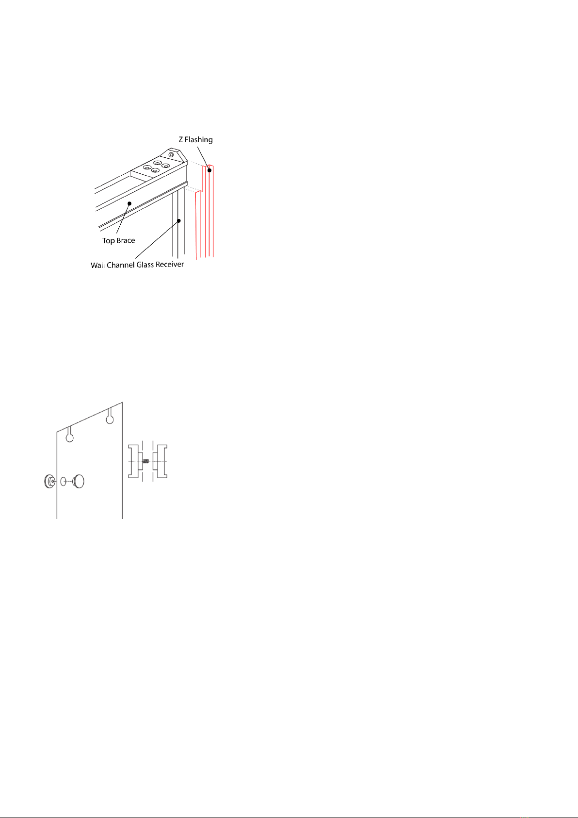
19. HANDLE INSTALLATION
Assemble the handles as shown. Clear gaskets
are supplied with
the handle.
Position one on
each side
between the
glass and handle.
* The stainless steel handle assembly is optional
20. SILL INFILL
Trim the sill infill to fit between the fixed panel
and the return panel. Apply a continuous bead
of clear silicon to each inside face of the base
channel and at
each end. Ensure
the ends of the
sill infill are
completely filled
and place the
infill into the
base channel in
the location as shown.
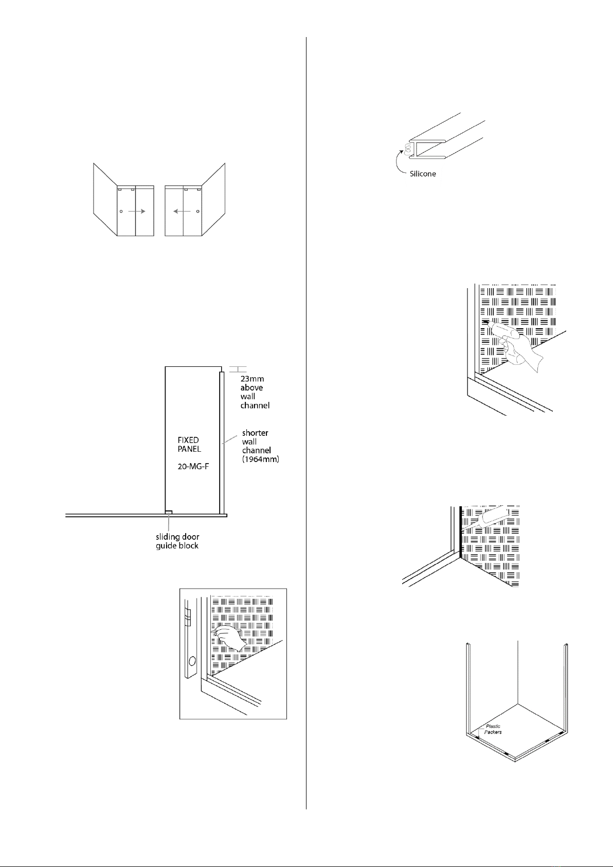
21. SLIDING DOOR GUIDE BLOCK
Ensure the guide block isn’t too tight (must
allow the glass to slide through it). Slide the
door as far back in an open position as possible.
Slip the sliding guide block under the door and
locate it in line with the end of the fixed panel
on the opening side.
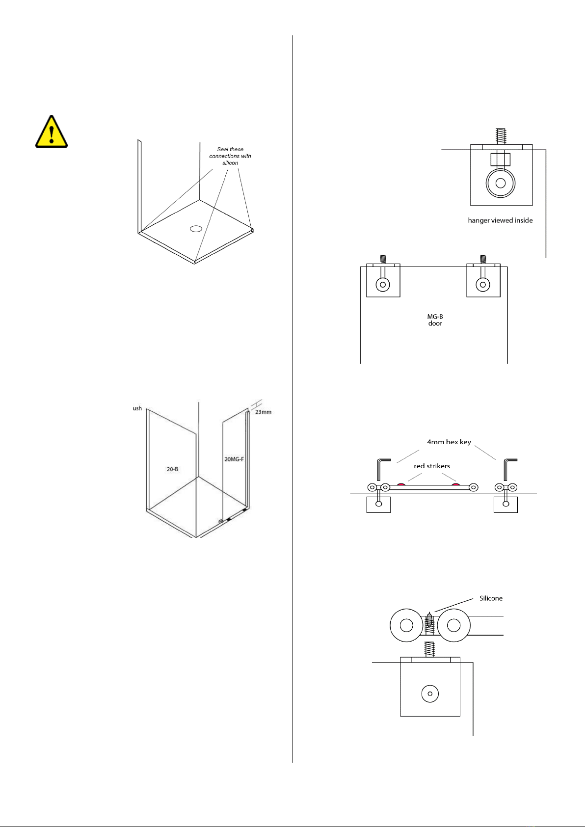
Apply a small bead of silicon to the bottom and
side of the block and then place into position –
firmly to the inside of the glazing channel. Use
adequate clear packers on the outside of the
glass to firmly press the glass against the guide
block. Tape glass and block into place to ensure
they do not move while silicon cures.
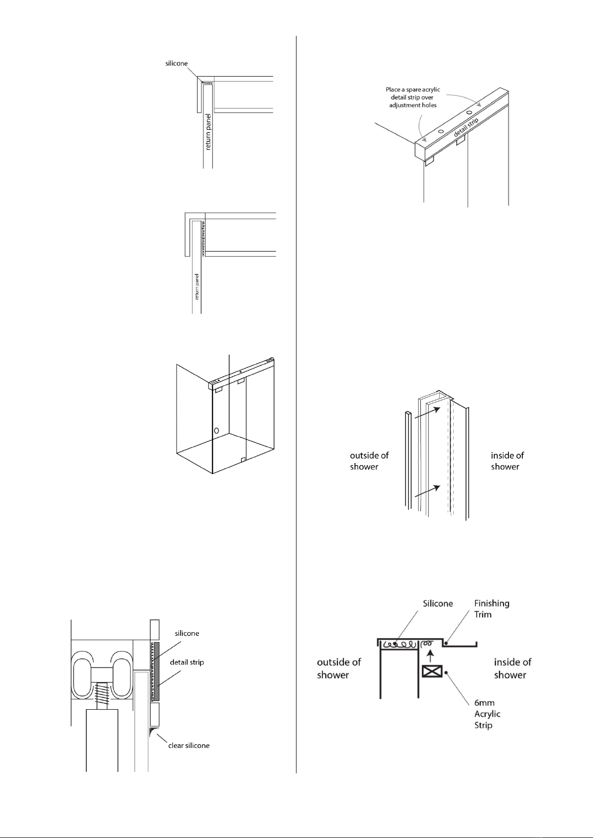
23. CLEAR FLEXIBLE WEDGE
2x lengths of clear flexible wedge have been
supplied. Wedge can be inserted into wall
channel, outside of glass panel. This will hold
panel in position, prior to final silicone seal.
These are to be used at installer discretion.
Wedge is not to be used in base channel.
Base channel is to be siliconed as per below.
24. SILICON APPLICATION
Using the blue tape supplied, mask the glazing
channels and glass at the intersections as
previously shown. Apply clear silicon to the
inside and outside of the base and wall receiver
channels. Use a spatula to remove the excess
silicon. Remove the masking tape immediately
after application.