Atlas PV-15PX User manual

1
MODEL: PV15PX
Revised 05/25/2021

2
CONTENTS
Product Features and Specifications ................................................3
Installation Requirement ...............................................................4
Steps of Installation .....................................................................6
Exploded View .............................................................................27
Test Run .....................................................................................36
Operation Instruction ...................................................................39
Maintenance ...............................................................................39
Trouble Shooting .........................................................................40
Lift Disposal ...............................................................................40
Warranty ….................................................................................41

3
I. PRODUCT FEATURES AND SPECIFICATIONS
CLEAR-FLOOR DIRECT-DRIVE MODEL FEATURES
Model PV15PX (See Fig. 1)
· Direct-drive design, minimizes the lift wear parts and breakdown ratio
· Dual hydraulic cylinders, designed and made to high standards, utilizing imported
oil seals in cylinder
· Self-lubricating UHMW Polyethylene sliders and bronze bushings
· Single-point safety release with dual safety design
. Clear-floor design, provides unobstructed floor use
. Overhead safety shut-off device prevents vehicle damage
. Adjustable heights to accommodate varying ceiling heights
MODEL PV15PX SPECIFICATIONS
Arm Swings View
Model
Style
Lifting
Capacity
Lifting
Time
Lifting Height
Overall Height
Overall
Width
Minimum
Pad Height
Motor
PV15
Clear-floor
Direct-drive
15,000lbs
(6800kg)
90s
75 ¼” - 84 ¼”
174”/198”
(4420/5029mm)
150 3/4”
(3829mm)
7 1/4”-16 1/4”
(185-414mm)
2.0HP
Fig. 2
109 3/4”
150 3/4”

4
II. INSTALLATION REQUIREMENT
A. TOOLS REQUIRED
Rotary Hammer Drill (Φ19)Carpenter’s Chalk
Hammer Screw Sets
Level Bar Tape Measure (7.5m)
English Spanner (12") Pliers
Wrench set:(10#、13#、14#、15#、17#Lock Wrench
19#、24#、27#、30#)
Ratchet Spanner With Socket (28#)
Fig.3
Socket Head Wrench (3#, 5#, 8#)

5
B. Equipment storage and installation requirements.
The equipment should be stored or installed in a shady, normal temperature,
ventilated and dry place.
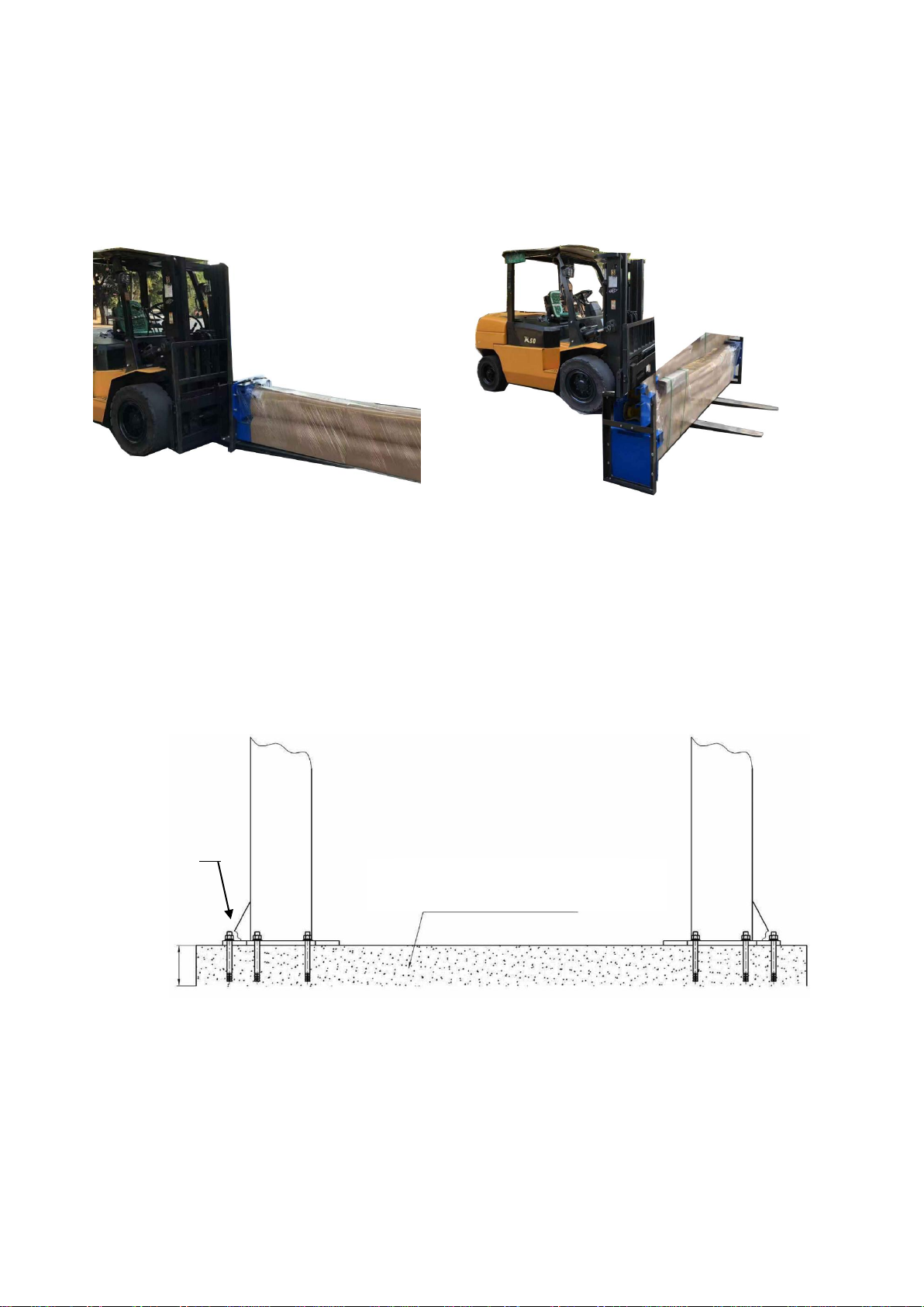
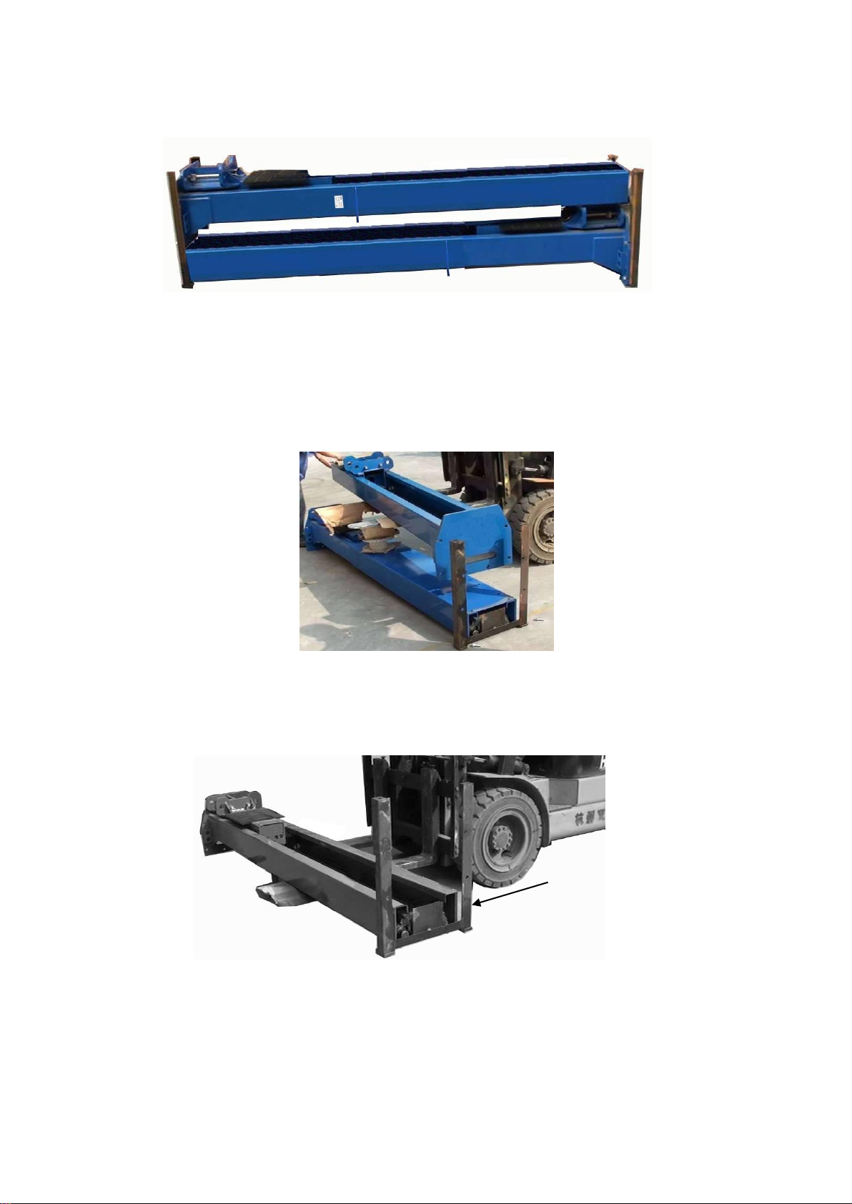
C. The equipment should be unloaded and transferred by forklift.
D. SPECIFICATIONS OF CONCRETE (See Fig. 5)
Concrete must adhere to the specifications listed below, failure to do so
may result in lift and/or vehicle falling.
1. Concrete must be thickness 6”minimum and without reinforcing steel bars, and
must be totally dry before lift installation.
2. Concrete must be in good condition and must be of test strength 3,000psi
(245kg/cm²) minimum.
3. Floors must be level with no cracks or holes.
E. POWER SUPPLY
220volt single phase source on a 30amp breaker with minimum of 10 gauge
wire running to the power unit. Operating voltage range is 208v-230v.
Fig.4
Fig. 5
Concrete intensity must be 3,000psi
6”
¾”

6
III.INSTALLATION STEPS
A. Location of installation
Check and ensure the installation location (concrete, layout, space size etc.) is
suitable for lift installation.
B. Use a carpenter’s chalk line to establish installation layout of columns (See Fig. 6)
C. Check the parts before assembly.
1. Packaged lift, hydraulic power unit and parts box: (See Fig. 7).
2. Move the lift aside with a forklift or hoist and open the outer packing carefully
(See Fig. 8).
Shipment Parts list
Fig. 7
Fig. 8
Outer column
Fig. 6
Parts box
Chalk a line
150 3/4”

7
3. Remove 2 outer columns, then move the inner column to the installation site.
(See Fig. 9).
4. Lift the upper column with a forklift or hoist, loosen the bolts of the upper package
stand, take out the parts in the inner column (See Fig. 10).
5. Lift the lower column with a forklift or hoist, take down the package stand, than take
off the lower outer column, take out the parts in the inner column (See Fig. 11).
Fig. 9
Fig. 10
Fig. 11
Open the package

8
6. Move aside the parts and check the parts according to the shipment parts list
(See Fig. 12, Fig. 13)
7. Check the parts of the parts bag 1 according to parts bag list (See Fig. 14).
8. Check the parts of the parts bag 2 according to parts bag list (See Fig. 15).
103
Fig. 15
Fig. 14
Fig. 12
Fig. 13
Parts of 103

9
D. Install parts of extension columns (See Fig. 16).
E. Install hydraulic cylinder
Apply thread tape to both ends of extended straight fitting, connect the 90° fitting, connect
both to cylinder, and then install the cylinder in the carriages (See Fig. 17).
Fig. 16
20
37
25
24
26
41
42
1
67
52
93
94
69

10
F. Install columns
Lay down two columns on the installation site parallel, position the power-side column
according to the actual installation site. Usually, it is suggested to install power-side
column on the right side of vehicles drive-in. This lift is designed with 2-Section columns,
adjust height according to the ceiling height and by connecting the inner and outer
columns as shown in Fig 18 or Fig 19.
If the ceiling height is over 199”, it can be installed in a high setting; if the ceiling height
between 175”–199”, it can be installed in the low setting; it is not recommended to
install if the ceiling height less than 175”.
1. High Setting, connecting the outer columns with the lower hole (See Fig. 19).
2. Low Setting: connecting the extension columns with the upper hole (See Fig.19).
Fig. 18 High setting
Fig. 17
Fig. 19 Low setting
Place fitting in the
cylinder toward the hole
in the column
Thread
tape
Assemble the
cylinder into the
column
95
23
21
22

11
F. Position the Columns & Install anchor bolts.
Position the columns on the installation layout of base plate. Install the anchor bolts. Check the
columns plumbness with level bar and adjust with shims if the columns are not vertical. Do not
tighten the anchor bolts (See Fig.20)
Fig. 20
Adjusting with
the shim
Drilling
Cleaning
Bolting
6
3/8”
Note: Minimum embedment of anchors is 6”.
57
56
Width between
columns: 123 1/2”
Overall width:150 3/4”

12
H. Install overhead top beam
1. With help of the hook of top beam, put one side of top beam on top of the extension
column and connecting the top beam to extension column by bolts, tighten the bolts.
Then assemble the connecting bracket (See Fig. 21).
Fig. 21
Hook on to the
extension columns
Tighten the bolts
23
22
21
27
1

13
2. Assemble overhead top beam, tighten the columns anchor bolts (See Fig. 22).
Tighten the anchor bolts
with ratchet spanner with
socket
Fig. 22
Note: Torque of Anchors is
150N.m. or 110 Ft lbs.
27
28
23
22
21
a
1
52

14
I. Installing the limit switch control bar and limit switch (See Fig. 23).
Fig. 23
NC: Normal contact
Loosen Screw of
Drive Rod for
adjustment, Tighten
the screw after
adjustment
Limit Switch is
connected
with cable
Connect the yellow
and green wire to
the terminal earth
wire of limit switch
and terminal earth
wire of power unit.
Connect the brown
wire to terminal 12#
of limit switch and
terminal L1 of
control button.
Connect the blue
wire to terminal 11#
of limit switch and
terminal A1 of AC
contactor of power
unit.
65
97
96
23
99
21
22
61
59
98
52

15
J. Install safety device (See Fig. 24 & Fig. 25).
Fig. 24 Power-side safety device
Fig. 25 Off-side safety device
12
13
14
15
16
17
1
8
7
10
11
100
24
18
19
9
21
6
12
13
14
44
45
17
52
19
18
40
50
24
51
24
100
47
46
43
38
39

16
K. Raise the carriages up by hand so they are locked at the same level (See Fig. 26).
Fig. 26

17
L. Install cables
1. High setting cable connection.
1.1 Take out the carriage’s plastic cover, cable pass through from the bottom of the
carriages and pull out from the opening in the carriages, then screw on the two cable
nuts (See Fig. 27).
Fig. 27
Cable connecting
direction
Cable connecting
direction
Tighten

18
1.2 Connecting cable for high setting (See Fig. 28)
Fig. 28
High setting
Cable 1
Cable 2
Cable 1

19
2. Low setting cable connection. (See Fig. 29).
Note: Cable should go inside of the carriage.
107
Cable 1
Cable 2
Fig. 29
Low Setting
Cable 2
108

20
M. Install power unit (See Fig. 30)
Fig. 30
Other manuals for PV-15PX
2
Table of contents
Popular Automatic Barrier manuals by other brands

Centurion
Centurion SECTOR II installation manual

Bauer
Bauer S-BAR Instructions and warnings for installation and use

BFT
BFT Maxima Ultra 36 Instructions for installation, use and maintenance

O&O
O&O NIGHT&DAY 35 Xtreme Instructions for installation, use and maintenance

Palfinger
Palfinger ILSL 30 owner's manual

Next Systems
Next Systems ALLAR0415 B 56 Technical manual