- 3 -
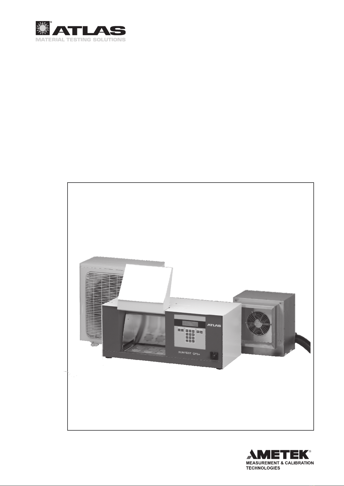
Operating Manual SunCool for SUNTEST® CPS+
Contents Page
1 Instructions for safe operation ...................................................................................................................... 5
1.1 Explanation of the symbols .......................................................................................................................... 7
1.2 General safety instructions ........................................................................................................................... 8
1.3 Safety instructions for coolants .................................................................................................................. 10
2 Delivery of the instrument ............................................................................................................................ 12
2.1 Packaging .................................................................................................................................................. 12
2.2 Scope of delivery ........................................................................................................................................ 12
3 Requirements for the installation site ......................................................................................................... 13
3.1 Room climate ............................................................................................................................................. 13
3.2 Room ventilation ........................................................................................................................................ 13
3.3 Installation .................................................................................................................................................. 13
3.4 Heat sources .............................................................................................................................................. 14
3.5 Transport .................................................................................................................................................... 14
3.6 Effects of vibration ...................................................................................................................................... 14
3.7 Installation and space requirements .......................................................................................................... 15
4 Description of the instrument ...................................................................................................................... 16
4.1 SunCool Components ................................................................................................................................ 16
5 Functional description .................................................................................................................................. 17
5.1 SunCool funktionality ................................................................................................................................. 17
5.2 Setting the test parameters ........................................................................................................................ 17
6 SunCool start up ........................................................................................................................................... 18
6.1 Preparatory measures ................................................................................................................................ 18
6.2 Starting for the rst time ............................................................................................................................. 19
6.3 Checking the instrument components ........................................................................................................ 19
6.4 Closing the coolant circuit .......................................................................................................................... 20
6.5 Indoor installation of the liqueer unit ......................................................................................................... 21
6.6 Outdoor installation of the liqueer unit ...................................................................................................... 22
6.7 Main power supply ..................................................................................................................................... 25
7 Operation ....................................................................................................................................................... 26
7.1 Menu structure of the device controller ...................................................................................................... 26
7.2 Setting the SunCool accessory .................................................................................................................. 26
7.3 Starting the cooling process ....................................................................................................................... 27
8 Taking out of operation ................................................................................................................................. 28
8.1 Switching off the instrument ....................................................................................................................... 28
8.2 Switching off the instrument in an emergency ........................................................................................... 28
8.3 Decommissioning of instrument ................................................................................................................. 28
9 Troubleshooting ............................................................................................................................................ 30
9.1 Error messages and troubleshooting ......................................................................................................... 30
10 Maintenance .................................................................................................................................................. 30
10.1 Inspection ................................................................................................................................................... 30
10.2 Repair ......................................................................................................................................................... 30
10.3 Maintenance ............................................................................................................................................... 31
10.4 Cleaning ..................................................................................................................................................... 31
11 Technical Data ............................................................................................................................................... 32
12 Accessories .................................................................................................................................................. 33
13 Declaration of conformity ............................................................................................................................ 34
14. Notes ............................................................................................................................................................. 35