Atlas O Scale 21st Century Signal User manual

21
21st
st Centur
Century Signal System
y Signal System™
™
2-Rail Manual
2-Rail Manual
Scale Track System
Scale Track System

1
TABLE OF CONTENTS
Introduction..................................................................................................................2-3
Road Signal Board Diagram and Definitions ..................................................................4-6
Tips for Handling the Circuit Board ..................................................................................6
2-Rail Detector Board Diagram and Definitions ................................................................7
The Basic Installation of One Signal ..............................................................................7-9
How to Make an Insulated Rail Section ..........................................................................10
Installing the 2nd Signal: Adding the Multiple Integration Feature................................11-12
Approach Mode and Bi-Directional Signaling with Examples ......................................13-15
Setting the Jumper Plugs ................................................................................................16
How to Use the DOUT Feature........................................................................................17
Atlas O Signal System Product Listing ............................................................................18
Contact Information ......................................................................................................18
Warranty ........................................................................................................Back Cover

2
INTRODUCTION
Dear "O" Enthusiast,
Prototype signal systems are one of the most familiar trackside details to be incorpo-
rated on miniature rail systems. Ever since the modern position light signals were intro-
duced by the railroads in the mid-1920's, model train manufacturers have been eager
to offer them as the quintessential layout accessory. While capturing the appearance
of the real thing, operation, in most cases, has been far less than prototypical...until
now.
The Atlas O 21st Century Signal™System represents a quantum leap in model signal
operation and design. By following the simple installation instructions, the realistic sig-
nal structures will provide you with prototypical operation that can be tailored to any
layout. The signal circuit board is the "heart" of the system. Installed in the detailed
trackside relay shed (or mounted under your layout), the circuit board is capable of
four modes of signal operation:
• Stand-Alone Signal Operation - Each signal is completely independent and
gives a timed Red-Yellow-Green aspect operation. (Simplest hook-up)
• Integrated Operation - Each signal is connected together and the Red-Yellow
Green aspects are controlled by the blocks and signals in front of and behind your
train. Hook-up between signals is accomplished easily with the Atlas O Signal Cable
(Items #6937-6939), pre-packaged in lengths of 7', 15' and 25'.

3
• Approach-Only Signal Operation - On some prototype railroads, signals
are off until a train approaches. The Atlas O Signal system has the provisions to
duplicate this operation.
• Complex Signaling (in conjunction with the signals and signal boards offered
by Custom Signals, Inc.) - The Atlas O Signal System has been designed to be fully
compatible with the products offered by Custom Signals, Inc., one of the hobby's
premier custom signal builders.
As you can see by the features included with Atlas O's 21st Century Signal System,
expert knowledge of the prototype was essential. Many hours and intense research
were put into the design of the system to achieve prototype operation in a user-friend-
ly manner. As a result, I would like to thank the following individuals who have assist-
ed with this project from concept to realization: Gary Emmich, Steve Horvath and Terry
Christopher.
Happy Railroading!
Sincerely,
Jim Weaver,
Vice President, Atlas O, LLC

4
SIGNAL CONTROL BOARD
The signal control board is the "electronic
brain" behind the operation of the signal
system. By taking a few minutes to study
the diagram and read the definitions, you
can familiarize yourself with the overall
operation of the signal system.
DEFINITIONS
1. J1- (Jack 1) - J1 is used for multiple inte-
grated installations only. In integrated installa-
tions, J1 is plugged into J2 of the following
board. Atlas O carries a variety of modular con-
nectors in 7',15', and 25' lengths, (Item #'s
6937-6939). See page 11 for further explana-
tion of integrated installation.
2. J2- (Jack 2) - See J1 above.
3. J3- (Jack 3) - J3 is the connection for the 8
pin modular jack from the signal itself.
4. J4- (Jack 4) - J4 is a screw-type power
connection terminal strip. It allows stand-alone
or daisy-chaining of power leads.
SIGNAL CONTROL
BOARD

5
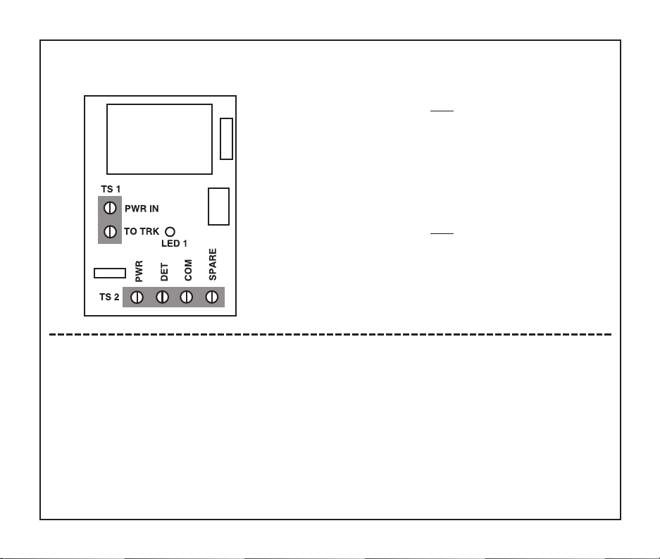
a. COM - COM is the common, or ground. In stand-alone installation, it is connected to the
power supply. Power is 6-22 volts AC or DC. While the signal system will run on AC,
Atlas O recommends DC for expansion. Use black wire.*
b. PWR - PWR is the positive or (hot) AC or DC power. In stand-alone installation, it is connected
to the power supply. Use red wire.
c. COM - The second COM connection is used in multiple integrated installations. This COM is
connected to the next signal board. Use black wire.
d. PWR - The second PWR connection is also used in multiple integrated installations. This PWR
is also connected to the next signal board. Use red wire.
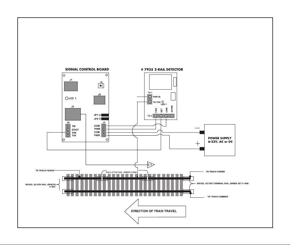
5. J5- (Jack 5) - J5 is a screw-type connection strip used for input/output connections.
a. TM - TM is the turnout module connection. It can be connected to either the Atlas O switch
signal control board for correct output to block signal control board #6930, or to Custom Signals
turnout signal control board. Use blue wire.
b. DOUT - DOUT is the optional detector output. It is used to connect an auxiliary piece of
equipment, (no more than +5VDC), such as an LED or relay. Wire color optional.
c. DIN - DIN is the detector input. It is connected to the insulated rail detector lead, (or the
detector lead from the Atlas O 2-rail detector board, (#7935 in 2-rail installations). Use green wire.
d. YIN - YIN is the yellow input. This connection is used if a second insulated block is planned to
control the yellow "aspect" of the signal independent of the "timed" yellow, which is the default
setting. Use yellow wire.

6
6. J6AIN- (Jumper 6) - J6AIN is the approach input. It is a solder pad that is used with the "approach”
lighting feature.
7. JP1- (Jumper 1) - JP1 is used for “approach” lighting options. Both JP1 and JP2 come from the facto-
ry with the jumper plugs covered by a black plastic cap.
8. JP2- (Jumper 2) - JP2 is used for searchlight style signals that use a single bi-color LED for three color
output, available from Custom Signals.
9. LED1 - LED 1 is used to indicate whether the correct power is going to the circuit board. If lit, it is correct.
*(Please note-Atlas O recommends their readily available brand of 20 gauge, multi-stranded copper wire that comes in a variety
of colors, Item#'s 315-#319.
TIPS FOR HANDLING THE SIGNAL SYSTEM CIRCUIT BOARD
When handling the signal system circuit board, it is important to follow these simple guidelines to prevent any damage to the cir-
cuit board.
1. Unplug your power source before attempting to handle the signal circuit board.
2. Touch some type of metal surface. This action helps protect the circuit board from any damage that could be caused by
electrostatic discharge.
3. To avoid generating static electricity, do not walk around the room until you have completed handling or mounting the circuit
board.
4. Hold the board by its corners, taking care not to touch the components on the circuit board.
5. Turn off your power supply after every operating session.

7
DEFINITIONS
TS1
PWR IN - Power from transformer or power supply
TO TRACK - Wire to insulated rail used in “Block”
LED 1 - Used for visual indication of “Block” occupancy. Will be
lit whenever “Block” is occupied
TS2
PWR - Circuit board power 6-22VAC or DC
DET - Detector output connects to “DIN” of Signal Control Board
COM - Common or return from power supply
SPARE - Unused
#7935
2-RAIL DETECTOR BOARD
THE BASIC INSTALLATION OF ONE SIGNAL
Now that you have familiarized yourself with the signal board and detector diagrams and def-
initions on pages 4-7, you are ready to install your first signal using the diagram found below.
The initial step is to determine the signal location. The signal is normally placed at the entrance
to a block. (A block is any section of track that is electrically isolated from the rest of the lay-
out.) Next to a straight track, the signal should be positioned approximately 2-3 inches from
the outside track edge. Placing a signal on a radius should be carefully done in consideration
of your longest rolling stock. Experiment with a variety of cars to determine the correct space
from the outside track edge.

8
POWER SUPPLY
TO TRACK
BASIC
INSTALLATION
DIAGRAM
The signal board will be located either within the silver shed that comes with both the single and
four pack kits, (Item #’s 7930 and #7934) or it may be mounted under the table with the sup-
plied bracket. The shed can be located on either side of the track in relation to the signal. They
should, however, be in close proximity to one another as determined by the length of the signal
wire. (See diagrams on right for detailed shed and under the table positioning and installation.)

9
Drill a 5/8” hole under the middle
of relay shed location. Run the red
and black power wires from the J4
terminal strip, (PWR) of the signal
board to power leads of the
unplugged source of power, (6-
22VAC or DC power pack).
Create an insulated rail section of
track. (See page 10 for detailed
instructions.) Connect the wire
from the DET terminal of the detec-
tor board to the J5 terminal strip
marked DIN on the signal board.
Drill a 1/2” hole under the signal
location and drop the plug from
your signal into the hole and work
it up through the relay shed hole.
Plug the 8 pin signal jack into the
input marked J3 on the signal
board. The installation is now
complete.
Please Note: The detector board can be attached to the underside of the layout table using double-sided foam tape.

10
HOW TO MAKE AN INSULATED RAIL SECTION
USING ATLAS O TRACK
For best results when using insulated track rails in conjunction with the detector, it is recom-
mended to use a minimum of three 10" sections, (Item #7050), or more. As shown in the dia-
gram below, remove two nickel silver rail joiners, (Item #7091), from one of the running rails
and replace with plastic insulated rail joiners, (Item #7093). Between the two insulated rail join-
ers, solder a detector wire (green) to one of the #7091 nickel silver joiners of the intermediate
track sections (Please Note: #7090 Terminal Joiners may also be used). The wire should be of
sufficient length to reach the Detector board and is connected to the TO TRACK terminal on the
Detector. (#7091 – Solid rectangles in diagram/#7093 – Hollow rectangles in diagram)

11
INSTALLING INTEGRATED
OPERATION OF 2 OR MORE
SIGNALS
To add integrated signal operation of two
or more signals, you need to plug in the
modular Atlas O Signal Cable (Items
#6937- 6939) in the length that is appro-
priate for your block size. The cable is
available in lengths of 7’, 15’ and 25’.
Plug one end of the cable into J1 of the first
signal board. The other end will go into J2
of the second signal board. Repeat for
every signal.
Installation of the integrated Signal Cable
automatically disengages the timed Red-
Yellow-Green aspect operation of the
stand-alone signal. All aspects are now
under full control of the blocks and signals
in-front-of and behind your train.

12

13
APPROACH MODE
On some prototype railroads, the signals remain unlit until a train is approaching. The Atlas O
Signal System has the provisions to duplicate this operation. In the diagram below, Signal #1,
which is connected to Block #2, will remain dark until a train enters Block #1. The signal will
then light green for the approaching train.
For stand-alone signal operation, a wire from an insulated rail section in the block ahead of the
signal, must be connected to a 2-Rail Detector board (Item #7935) to the TO TRACK terminal
on the detector. A wire is then run from the DET terminal of the Detector to the J6 pad on the

14
Signal Circuit Board. The wire must be soldered to this pad. Also, a wire from an insulated rail
section behind the signal must be connected, through a Detector board, to the YIN terminal of
the J5 strip on the Signal Circuit Board. The enclosed jumper plug must be installed across the
JP1 pins, (see page 15).
The signal will now follow the pattern of "Off – Green – Red – Off". If a train is occupying Block
#2 and another train enters Block #1, the signal will be red. Similarly, if a train is occupying
Block #3 and another enters Block #1, the signal will have a yellow aspect.
If you are using a fully-
integrated wiring
scheme, and all of the
signals are connected
with the Atlas O Signal
Cables, approach
lighting is very easy.
Only the jumper plugs
across the JP1 pins on
each of the signal cir-
cuit boards is
required. Separate
wires and detectors for
the J6 and YIN termi-
nals are not necessary.
TYPICAL INTEGRATED
ONE-DIRECTIONAL SIGNAL SET-UP

15
TYPICAL INTEGRATED BI-DIRECTIONAL SIGNAL SET-UP

16
SETTING THE JUMPER PLUGS
The jumper plugs are found on the right hand side of the signal board, location JP1 and JP2. The default,
(as delivered) setting has both jumpers partially covered. Basic stand-alone and integrated operation will
not require movement of these plugs. The caps are moved into different positions if approach mode,
search light, or more advanced optional features are wanted. If needed, the caps may be removed by
carefully inserting a knife along the bottom edge of the plastic cap and gently twisting the plastic up. Use
the following chart with the corresponding examples below to determine the correct jumper settings for
your usage:
Example Description
ABoth jumpers are partially covered-This is the standard, default setting.
Neither approach nor searchlight features are active.
BThe JP1 plug is covered and the JP2 is uncovered-This setting initiates the
approach mode option explained on pages 13 and 14 in this manual.
CThe JP2 plug is covered and the JP1 plug is uncovered. This is used only on
signals using a single bi-color LED. This option allows the yellow aspect
to be added to the bi-color LED.
DJP1 and JP2 are covered. This would be used if you installed a searchlight
style target using a bi-color LED and you wanted it to work in the approach
mode.

17
HOW TO USE THE DOUT OPTIONAL FEATURE
DOUT stands for detector output which is located on the lower left hand side J5 terminal strip of the sig-
nal control circuit board, (see diagram below). It is used to connect an auxiliary piece of equipment such
as a control panel LED or a relay. An important point to keep in mind is that whatever optional piece of
equipment you install, it cannot have an operating current that exceeds +5VDC.
The below diagram illustrates some basic applications that can be accomplished by utilizing the output of
the DOUT lead found at J5 on the signal board. The top application, shown to the left of the board, rep-
resents an LED that could be mounted in a control panel setting where the operator wants to see a visual
indication of what blocks are occupied without leaving the control panel. A second application pictures
the coil of a relay. This relay could be used to operate a variety of other applications by using the contact
sets, (DPDT relay), associated with the relay.
In the above examples, the LED would be lit for the
entire time the insulated block associated with that sig-
nal control board was occupied. The same is true for the
relay. The output of the “DOUT” lead follows the condi-
tion of the “DIN” lead (when “DIN” is active “DOUT”
will go active).

18
ATLAS O 21ST CENTURY SIGNAL SYSTEM™ PRODUCTS
CONTACT INFORMATION
If you have any questions about operating or installing your Atlas O Signal System, please
call 908-687-9590 (Steve, ext. 7142).
For more information about compatible signal products, please visit the Custom Signals web
site at http://www.customsignals.com or call 845-643-1318.
2-RAIL ITEM# DESCRIPTION
7930 Realistic Road Signal - Type "G" signal -
red, green and yellow aspects. (Stand-alone operation)
7934 FOUR PACK Realistic Road Signal (SAVE!)
(Integrated operation)
7935 2-Rail Detector
6937 7' Signal Cable (use 3-Rail Item #)
6938 15' Signal Cable (use 3-Rail Item #)
6939 25' Signal Cable (use 3-Rail Item #)
To see a complete list of products that Atlas O has to offer, please visit your local hobby
store or check out http://www.atlasO.com. You may also send $5 to the address shown on
the back cover for a Track and Accessories Catalog.

WARRANTY
Atlas O, LLC. warrants that this Signal System product will be free from defects in material and
workmanship for a period of 90 days from the date of purchase. If this Signal System fails dur-
ing the warranty period, carefully pack the item in the original carton, together with the dated
sales receipt, and return to: Atlas O Signal System Warranty, 378 Florence Avenue, Hillside,
NJ 07205. Defects due to misuse, improper maintenance and/or abuse are not covered by the
warranty. Items that have been disassembled by the modeler or anyone other than an Atlas
repair person are not covered by the warranty. This warranty gives you specific legal rights and
you may also have other rights, which vary from state to state.
Atlas O, LLC. • 378 Florence Avenue • Hillside • NJ
07205 • USA • www.atlasO.com • 908-687-9590
CAUTION - This is an electrically operated product. It is not recommended for chil-
dren under 12 years of age, as with all electric products.
Precautions should be observed during the handling and use to reduce the risk of elec-
tric shock.
Please unplug your power source after you have finished your operating session.
Table of contents
Other Atlas Toy manuals
Popular Toy manuals by other brands

Fisher-Price
Fisher-Price Little People Disney Princess CGT78 Assembly instructions

Krick
Krick 20320 Building instructions

Eduard
Eduard F-105G Thunderchief interior S.A. manual

Lionel
Lionel Halloween Witch Pylon owner's manual

Zapf Creation
Zapf Creation Baby Annabell 702987 manual

REVELL
REVELL London Bus Assembling instructions