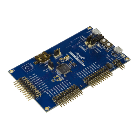
AT91SAM9263-EK Evaluation Board User Guide i
6325D–ATARM–26-Aug-09
Table of Contents
Section 1
Overview .................................................................................................................... 1-1
1.1 Scope................................................................................................................................. 1-1
1.2 Deliverables ....................................................................................................................... 1-1
1.3 AT91SAM9263-EK Evaluation Board ................................................................................ 1-1
Section 2
Setting Up the AT91SAM9263-EK Board................................................................... 2-1
2.1 Electrostatic Warning ......................................................................................................... 2-1
2.2 Requirements..................................................................................................................... 2-1
2.3 Layout ................................................................................................................................ 2-1
2.4 Powering Up the Board...................................................................................................... 2-4
2.5 Backup Power Supply........................................................................................................ 2-4
2.6 Getting Started................................................................................................................... 2-4
2.7 AT91SAM9263-EK Block Diagram .................................................................................... 2-5
Section 3
Board Description....................................................................................................... 3-1
3.1 AT91SAM9263 Microcontroller .......................................................................................... 3-1
3.2 AT91SAM9263 Block Diagram .......................................................................................... 3-4
3.3 Memory .............................................................................................................................. 3-5
3.4 Clock Circuitry.................................................................................................................... 3-5
3.5 Reset Circuitry ................................................................................................................... 3-5
3.6 Shutdown Controller ..........................................................................................................3-5
3.7 Power Supply Circuitry.......................................................................................................3-5
3.8 Remote Communication .................................................................................................... 3-5
3.9 Audio Stereo Interface .......................................................................................................3-6
3.10 User Interface .................................................................................................................... 3-6
3.11 Debug Interface ................................................................................................................. 3-6
3.12 Expansion Slot ................................................................................................................... 3-6
3.13 PIO Usage ......................................................................................................................... 3-7
Section 4
Configuration .............................................................................................................. 4-1
4.1 Configuration Jumpers and Straps .................................................................................... 4-1
Section 5
Schematics................................................................................................................. 5-1
