Atmos Cam 41 HD User manual
Operating Instructions
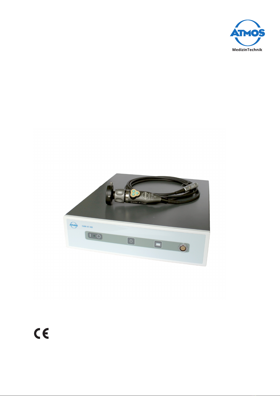
ATMOS®Cam 41 HD
English
GA1GB.150404.0
2017-07 Index 03

2
Table of contents
1 Introduction ................................... 3
1.1 Notes on operating instructions.......3
1.2 Explanation of pictures and
symbols................................................4
1.3 Intended use .......................................4
1.4 Function...............................................5
1.5 Intended users....................................6
1.6 Scope of delivery ................................6
1.7 Transport and Storage.......................6
2 Hints for your safety...................... 7
2.1 General safety information...............7
2.2 Dangers for users, patients and third
parties..................................................7
2.3 Damage to the device ........................7
3 Setting up and starting up ............ 9
3.1 Device overview..................................9
3.2 Connection diagram.........................10
3.3 Use with other devices ....................10
3.4 Connecting the device .....................11
4 Operation...................................... 12
4.1 Ambient conditions during
operation...........................................12
4.2 Switch on the device ........................12
4.3 Switchothedevice........................12
4.4 Connect and remove the camera
head ...................................................12
4.5 Attach and remove the lens
protection..........................................13
4.6 Connect and remove the
endoscope.........................................13
4.7 Set the buttons of the camera
head ...................................................14
4.7.1 Factory settings .............................14
4.7.2 Custom button assignment .........14
4.8 Adjust image ....................................15
4.8.1 Selectendoscopeprole..............15
4.8.2 Choose a light source ...................15
4.8.3 Sharpen the image........................16
4.8.4 Zoom...............................................16
4.9 Freeze or take pictures ....................16
4.10 Perform white balance ....................16
4.11 Perform pixel error correction .......16
5 Cleaning and Disinfection........... 18
5.1 Camera control unit .........................18
5.2 Camera head.....................................18
5.2.1 Manual cleaning and
disinfection ....................................18
5.2.2 Automated cleaning and
disinfection ....................................19
5.3 Recommended disinfectants ..........19
5.3.1 Instrument disinfectants ..............20
5.3.2 Surface disinfectant ......................20
6 Maintenance and Service............ 21
6.1 Period tests .......................................21
6.2 Function check..................................21
6.3 Replacing the fuse............................21
6.4 Sending in the device.......................22
7 Troubleshooting........................... 23
8 Accessories ................................... 24
9 Spare parts.................................... 25
10 Disposal......................................... 26
11 Technical data .............................. 27
12 Notes on EMC ............................... 29
13 For your notes .............................. 33
3Introduction
1 Introduction
1.1 Notes on operating instructions
These operating instructions contain important notes on how to oper-
ate the ATMOS®Cam41HDsafely,correctlyandeectively.
These operating instructions serve not only for new operating person-
nel to be instructed in its use, but also for use as a reference manual.
Any reprint - even in extracts - only after written permission from
ATMOS.
These operating instructions must always be kept available near
the device.
Care, period tests, regular cleaning and proper application are indis-
pensable. They guarantee the operational safety and usability of the
ATMOS®Cam 41 HD.
Maintenance, repairs and period tests may only be carried out by per-
sons who have the appropriate technical knowledge and are familiar
with the product. To carry out these measures the person must have
the necessary test devices and original spare parts.
Read chapter „2 Hints for your safety“ on page 7 before using the
deviceforthersttime.Thishelpsyouavoidpotentiallydangerous
situations.
The product ATMOS®Cam 41 HD bears CE marking CE according to the
EC Directive of the council for medical products 93/42/EEC and meets
the basic requirements of Appendix I of the directive.
The product ATMOS®Cam 41 HD complies with all applicable require-
ments of the Directive 2011/65/EC restricting the use of certain hazard-
ous substances in electrical and electronic equipment (“RoHS”).
The declaration of conformity and our general standard terms and
conditions can be obtained on our website at www.atmosmed.com.
ThequalitymanagementsystematATMOShasbeencertiedaccord-
ing to international standards EN ISO 13485.
These operating instructions are valid for the following devices:
• ATMOS®Cam 41 HD 507.5500.0

4Introduction
1.2 Explanation of pictures and symbols
In the operating instructions
DANGER
Warning of a danger which causes immediate death or serious injury. Observe the
necessary measures.
WARNING
Beware of a danger which can cause death or serious injury. Observe the necessary
measures.
CAUTION
Beware of a danger which can easily hurt you. Observe the necessary measures.
NOTICE
Indication of a danger where the product or other items can be damaged. Observe the
necessary measures.
Warning of a danger which can cause death or serious injury.
Information regarding possible material damage which can be caused.
&Useful information on the handling of the device.
1. Action. Go step by step.
.Result of an action.
Move, plug in this direction.
click Engage,checkcorrectt.
On device and type plate
Follow operating instructions
(blue)
Observe operating instructions
Manufacturer IP20 Degree of protection
SN Serial number REF Order number
This product complies with
the relevant requirements of
the EU-Directive
Application part type BF
Fuse Professional disposal
Freeze image (on camera
head)
Take a picture (on camera head)
Zoom (on camera head)
1.3 Intended use
Name: ATMOS®CAM 41 HD
Main functions: The ATMOS®CAM 41 HD is an endoscopy camera for displaying the

5Introduction
examination images on a monitor, PC or laptop and for storage of the video signal on a
digital recording device.
Medical indications / application: The camera is used for the examination on humans
and is intended to be connected to conventional endoscopes or to a microscope or
colposcope with an integrated beam splitter.
Specication of the main function: Camera head: High resolution CCD camera with
highlightsensitivityanddepthofeld.AllcommonstandardC-mountcouplerscanbe
mounted to the camera head for connection of endoscopes and for an easy endoscope
exchange. The three buttons on the camera head can be individually assigned with
dierentfunctionswhichareavailableonthecameracontrolunit.
Camera control unit: Via the operating panel on the front of the camera control unit all
basic functions are stored on the buttons.
Application organ: Throat, nose, ears, vagina, uterus, bladder, urethra and ureter.
Application time: Temporarily (max. of 60 minutes)
Application site: Application sites are clinics, surgery centres, outpatient clinics and
practices of ENT doctors, gynaecologists or urologists. The device may only be applied
by medical professionals.
Contraindications: Not intended for use in explosion-hazardous areas.
The product is: active
Sterility: The camera control unit, the connecting cable and the camera head are not
sterile, in the case of application a sterile drape is pulled over the camera head in a
sterile environment.
Single use product / reprocessing: No single use product
1.4 Function
The ATMOS®Cam 41 HD is a HD camera for displaying examination images on a HD
ready monitor or PC (software). The camera is designed for connection to conven-
tional endoscopes, hysteroscopes, microscopes or colposcopes with beam splitter.
The ATMOS®Cam 41 HD consists of a camera head and a camera control unit with an
endoscope coupler. The 3 m long connecting cable on the camera head is connected to
the camera control unit. The camera head includes a 1/3 “CCD colour image sensor with
microlenses for connection to commercially available endoscopes or hysteroscopes with
standard ocular objectives.
The product has no essential performance characteristics.
Technical description
Single sensor, 1/3“ full HD camera, with video output via DVI-D in HD, or 2 S-video
outputs or 2 composite video outputs, or an RGB output. Camera head with 3 m con-
necting cable to the camera control unit and 3 buttons. It may also be operated with a
stroboscope.
• Full HD DVI-D
• RGB output
• Ergonomic watertight aluminium camera head with three buttons
• Presets for the majority of operations (ENT)
• Image freeze function
• Anti-moire and 4 brightness levels
• Compatible with LED cold light sources
• Presets for LED light sources that can be switched at the camera head, status display

6Introduction
on the monitor
• Shutter mode for stroboscopy
1.5 Intended users
The operation and use of the camera must be performed by medically trained person-
nel.
1.6 Scope of delivery
1 x camera
control unit
1 x camera
head with con-
necting cable
1 x endoscope
coupler
1 x lens cap 1 x mains cable
1 x BNC cable 1 x S-video
cable
1x3.5mm
jack plug cable
stereo
1 x DVI cable 1 x VGA cable
1 x operating
instructions
1.7 Transport and Storage
Onlytransportthedeviceinashippingcontainer,whichispaddedandoerssucient
protection.
If damage occurs during transport:
1. Document and report the transport damage.
2. Fill in the form QD 434 “customer complaint/return shipment”. This form is enclosed
to each delivery and can be found at www.atmosmed.com.
3. Send in the device to ATMOS (chapter „6.4 Sending in the device“ on page 22).
Ambient conditions for transport and storage:
• Temperature: -20...+60°C
• Relativehumidity: 10...90%withoutcondensation
• Airpressure: 70...106kPa

7Hints for your safety
2 Hints for your safety
The safety of the ATMOS®Cam 41 HD complies with all the recognized rules of technolo-
gy and the guidelines of the Medical Products Law.
Read and follow the safety instructions carefully before using the product.
2.1 General safety information
Onlyuseaccessoriesandoptions,whicharespecicallysuitedforcombinationwiththe
product and which meet the performance and safety requirements.
If you wish to connect more than one device or application part, you must always
comply their safety instructions.
Only connect the device to the mains supply when the mains voltage and mains fre-
quency correspond to the local supply.
In the US, the device may only be operated according to Federal Law under the supervi-
sion of a physician.
2.2 Dangers for users, patients and third parties
Protect yourself against an electric shock!
Burns, cardiac arrhythmias and even death are possible.
• Check before each use if the device or the mains cable are damaged. Never operate
the device if you detect any damage. In this case please clean the device and send it
in to ATMOS for repair.
• Disconnect the device from the mains supply prior to cleaning or disinfection.
• Never touch the plug or mains cable with wet hands.
• Never operate the unit in high humidity environments.
• Do not allow moisture to penetrate into the device.
• Please pay attention to the period tests in chapter „6 Maintenance and Service“ on
page 21.
• Only use original accessories and original spare parts from ATMOS.
• Do not modify the device without the manufacturer's permission.
• Never touch the device´s interfaces and the patient at the same time!
• Only connect the device to a supply with a protective conductor.
Explosion and re hazard!
Burns and injuries are possible.
• Never operate the device in explosion-hazardous areas or areas which are oxygenat-
ed.
Reduce the risk of infection for you and your patients!
Deadly diseases can be transmitted.
• Clean the device after every use according to the operating instructions.
• Use a sterile drape for camera head and connecting cables, if necessary.
Only a fully functional product meets the safety requirements of users, patients and
third parties. Follow the following guidelines concerning your product.

8Hints for your safety
2.3 Damage to the device
Avoid sun and bright light sources.
The sensor in the camera head will be damaged.
• Attach the lens cover when you are not using the camera.
• Never hold the camera in the sun or in bright light sources.
Avoid incorrect handling, storage or transport
Connection cable, camera head or camera control unit could be damaged.
• Make sure that the connection cable is not pinched, squeezed, knotted or clamped
o.
• Do not pull on the connection cable.
• Please observe the ambient conditions regarding transport, storage, and operation.

9Setting up and starting up
3 Setting up and starting up
3.1 Device overview
Front view camera control unit
1 2 3 4 5
1Button
on/off
2Green LED
3Button
Light SouRCeS
4Button
Menu
5Camera head connection
Rear View camera control unit
1 2 3 4 5 6 78 9
1Video output DVI-D
2Video signal output S-Video
3Video signal output composite
4No function
5No function
6Video signal output RGB
7Jack for external control
8Potential equalization
9Mains supply
10 Setting up and starting up
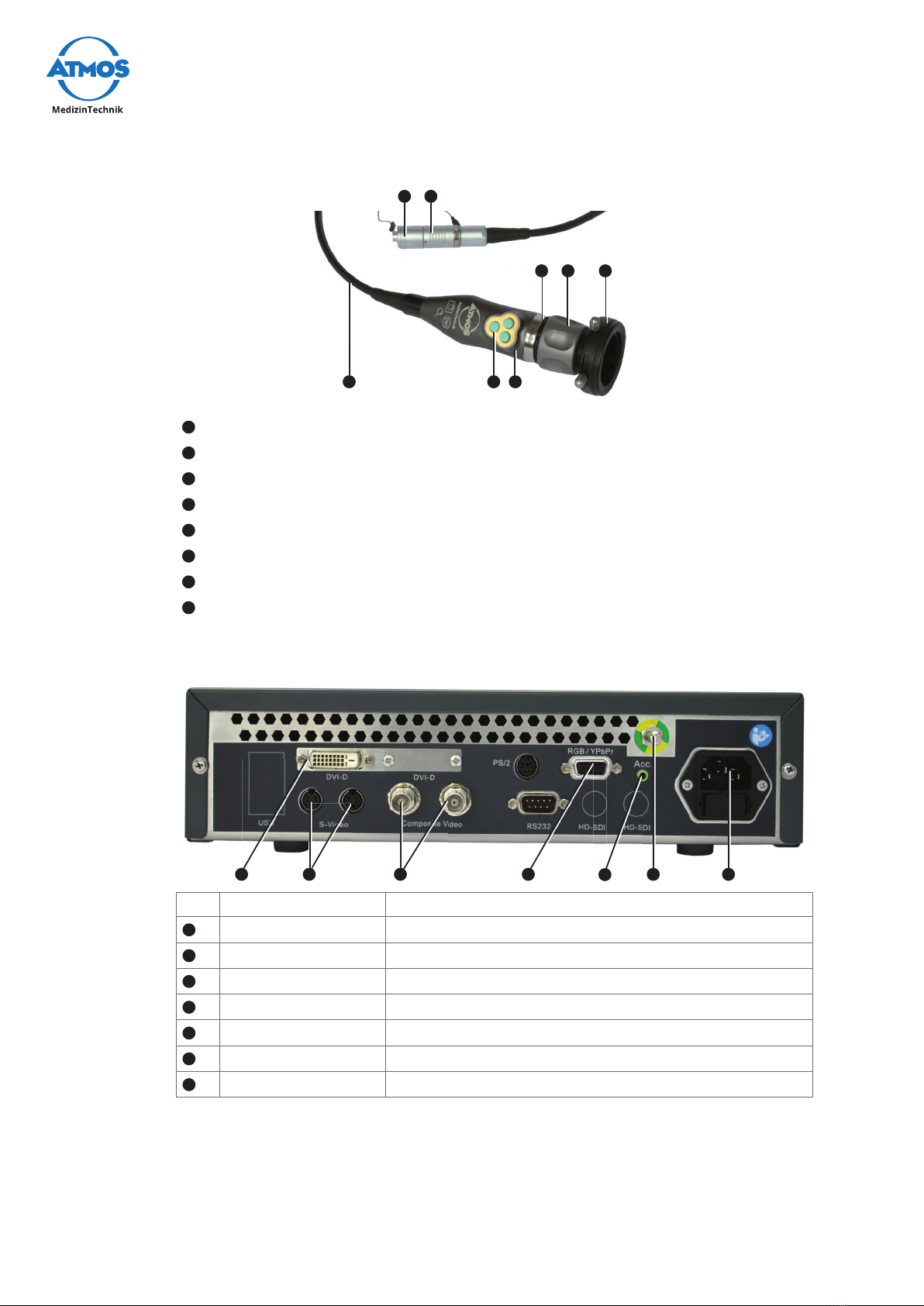
Camera head
1
6 7
8 2
345
1Focus wheel on the endoscope coupler
2Endoscope connection
3Camera head
4Camera head buttons
5Connection cable
6Cap for camera plug
7Camera plug
8Red sealing ring on the C-mount adapter
3.2 Connection diagram
1 2 3 6 78 9
No. Labelling Connection
1DVI-D Monitor
2S-Video Monitor or grabber
3Composite Video Monitor
6RGB/YPbPr Monitor
7Acc. Digital recorder
8Potential equalization
9Mains supply
3.3 Use with other devices
Onlyqualiedpersonnelmayinstallelectricalsystems.Thepersonwhoinstallsan
electrical medical system is responsible for ensuring that the performance, safety,

11Setting up and starting up
specicationsandintendeduseoftheATMOS®Cam41HDarenotaected.
Note the following when using the device in connection with other devices.
• RefertothespecicationsofIEC60601-1onmedicalelectricalsystems.
• Note in particular the information on the patient environment, multiple sockets and
leakage current.
3.4 Connecting the device
Carefully read the safety instructions in chapter „2 Hints for your safety“ on page 7
before using the product.
1. Check the device for any transport damage.
2. If the device is damaged: Document and report the transport damage. Send the
device to ATMOS, see chapter „6.4 Sending in the device“ on page 22.
3. Refer to the guidelines for medical electrical systems in chapter „3.3 Use with other
devices“ on page 10.
4. Connect a monitor.
5. Connect any additional components.
6. Connect the equipotential bonding if required.
&The equipotential bonding must be connected if the spatial environment in which
theproductisusedrequiresthis.RefertothespecicationsofIEC60601-1.
7. Check whether mains voltage and frequency of the device match with voltage and
frequency of the supply network.
&The device's details can be found on the type plate.
8. If the mains voltage and mains frequency correspond: Connect the device with the
supplied mains cable to a mains supply with a protective conductor.
9. Connect the camera head, see chapter „4.4 Connect and remove the camera head“
on page 12.
10. Perform a function check, see chapter „6.2 Function check“ on page 21.
12 Operation
4 Operation
4.1 Ambient conditions during operation
• Temperature: +10...+40°C
• Relativehumidity: 30...75%withoutcondensation
• Airpressure: 70...106kPa
4.2 Switch on the device
&Prior to each use perform a function check, see chapter „6.2 Function check“ on
page 21.
1. Press the button
on/ off
.
» The green LED on the
on / off
button illuminates.
» AwhitebackgroundwithanATMOSlogoappearsbrieyonthemonitor.
4.3 Switch off the device
1. Press the button
on/ off
.
» The green LED on the
on / off
button no longer illuminates.
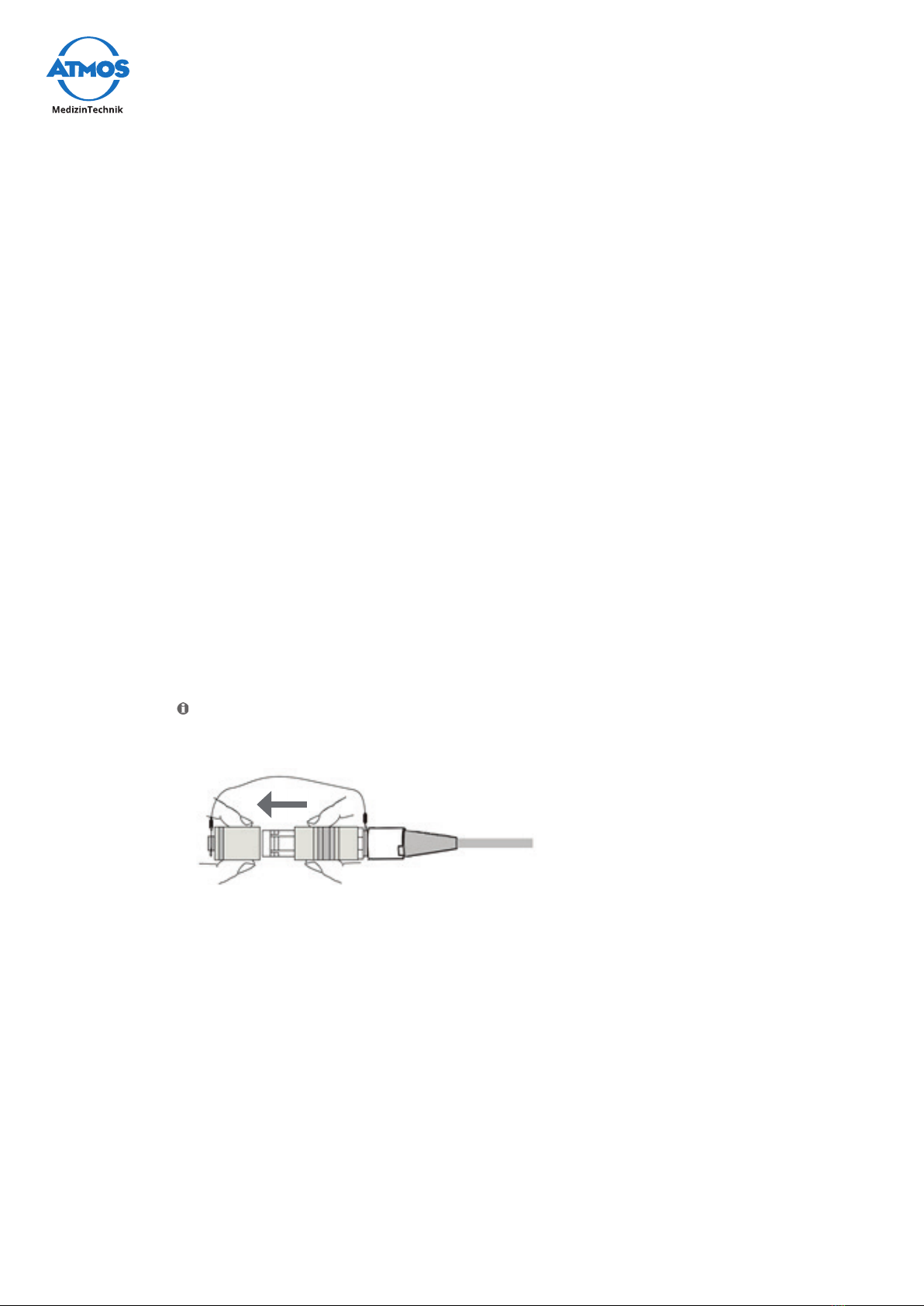
4.4 Connect and remove the camera head
Connect the camera head
1. Switchothedevice.
By forcibly pulling on the connecting wire of the cap for the camera plug it could
break.
2. Removethecapfromthecameraplugbypullingitrmly.
3. Insert the camera plug into the camera head with the red dot on the camera plug
facing upwards.
4. If you have connected a new camera head, then perform the following:
• White balance, see chapter „4.10 Perform white balance“ on page 16.
• Pixel Error Correction, see chapter „4.11 Perform pixel error correction“ on page
16.
Remove the camera head
1. Switchothedevice.
2. Remove the connecting cable plug from the camera head connector.
3. Attach the camera plug cap to the connecting cable:
13Operation
4.5 Attach and remove the lens protection
On one side the lens protection can be screwed to the camera head. On the other side
the lens protection can be attached to the endoscope connector of the endoscope
coupler.
Camera head
1. Screw the lens protection to the camera head.
Endoscope connection
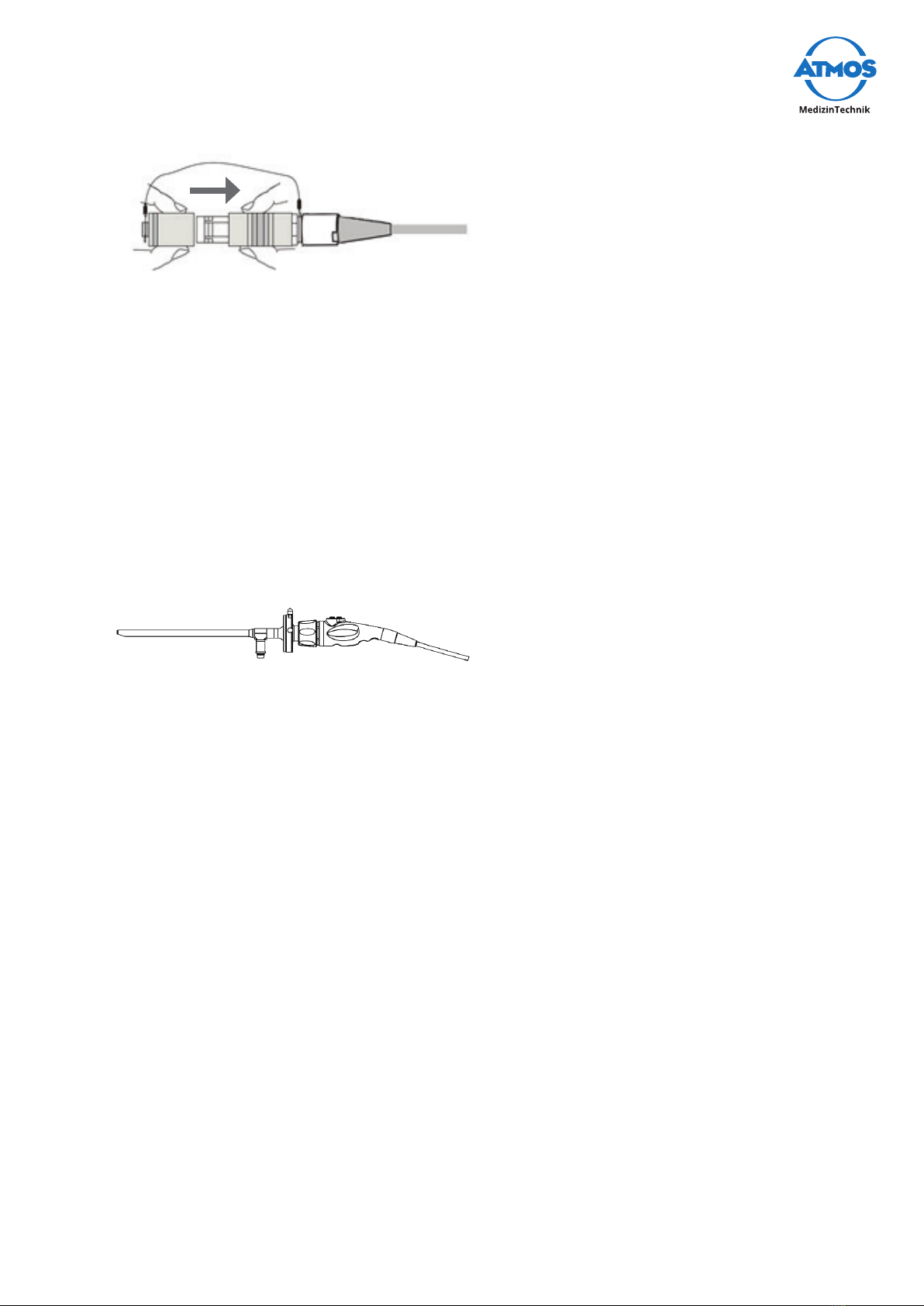
1. Slide the two pins on the endoscope connector together and insert the lens protec-
tion.
4.6 Connect and remove the endoscope
Connect the endoscope and endoscope coupler
&Once an endoscope is connected, a light source is required.
1. Remove the lens protection if applicable.
2. Check whether the camera head lens is clean and dry.
3. Check whether the glass surface of the endoscope coupler is clean and dry.
4. If the lens or glass surfaces are not clean and dry, then wash them in accordance
with chapter „5.2.1 Manual cleaning and disinfection“ on page 18.
5. Screw the C-mount adapter of the endoscope coupler to the camera head.
6. Push the two pins on the endoscope connector together and insert the endoscope.
7. Release the pins.
8. Checkthattheendoscopeisrmlyandsecurelyseated.
Remove endoscope and endoscope coupler
1. Remove the endoscope from the endoscope coupler.
2. Unscrew the endoscope coupler from the camera head.
3. Screw the lens protection to the camera head.
14 Operation
4.7 Set the buttons of the camera head
4.7.1 Factory settings
Button assignment during operation
Button Push duration Function
Left
Short Take a picture (only if recording device is
connected)
Long No function
Right
Short Freeze image
Long Rotate the image by 180 degrees
CentRe
Short Zoom in predetermined steps
Long Changeendoscopeprole
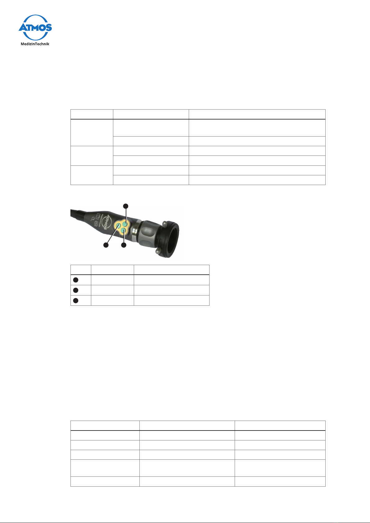
Button assignment in the setup menu
1
3 2
No. Button Function
1
Left
Upwards
2
Right
Downwards
3
CentRe
Select
Restore factory settings
&Thefactorysettingsareonlyresetfortheactiveendoscopeprole.
1. Brieypressthe
Menu
button on the front side of the camera control unit.
2. Assign any button with Factory, see chapter „4.7.2 Custom button assignment“ on
page 14.
3. Exit the setup menu.
4. Press the button assigned to Factory.
» The factory settings are restored.
4.7.2 Custom button assignment
The following functions can be assigned to the buttons on the camera head:
Display setup menu Function Setting options
Disabled Not assigned
Light up Set the display brighter Brighter in steps from 1 - 12
Light down Set the display darker Darker in steps from 12 - 1
Acc 1 Take a picture (only if record-
ing device is connected)
Acc 2 No function

15Operation
Display setup menu Function Setting options
Gain Amplication O;Min;Medium;High
AWB White balance
ABB Pixel error correction
Freeze Freeze image Freeze;release
Zoom up Increase zoom level 1.0 to 2.5
Zoom down Reduce zoom 2.5 to 1.0
Zoom Loop Continuous zoom levels 1.0;1.2;1.4;1.6
Mirror Mirror the image horizontally On;O
Rotate Rotate the image by 180
degrees
On;O
Flip Rotate the image by 180
degreesandiphorizontally
On;O
Color Temp Choose a light source LED;XENON;HALOGEN;USER
Menu Call up setup menu Call up - exit
Endo. User Changeendoscopeprole 10mm;8mm;2.7mm;
FLEXIBLE;FLEX+STROBO;
STROBO
Factory Reset button assignment
oftheendoscopeproleto
factory settings
Assign custom buttons
&Thebuttonscanbesetindividuallyforeachendoscopeprole.
1. BrieypresstheMenu button on the front side of the camera control unit.
» A menu with all buttons appears.
» An arrow appears next to the selected button.
2. Go to the desired button, by pressing the Left or Right button.
3. Press the CentRe button.
» Three dashes appear next to the selected button.
4. Press the Left or Right button to select the function.
5. Press the CentRe button.
» An arrow appears next to the selected button.
» The button is programmed with the desired function.
4.8 Adjust image
4.8.1 Select endoscope prole
1. Selecttheendoscopeproleaccordingtoyourcustombuttonassignment.
&Iftheimageispixelatedorblurry,youmayhaveanunsuitableendoscopeprole.
4.8.2 Choose a light source
&You can assign the selection of the light source on one of the camera head buttons.
1. Connect a light source to the endoscope.

16 Operation
2. Repeatedly press the Light SouRCeSbuttonbrieyonthefrontsideofthecamera
control unit to select the light source.
3. Perform a white balance. See chapter „4.10 Perform white balance“ on page 16.
&Ifthecolourtemperatureoftheprecedinglightsourcediersgreatly,youmayneed
to perform the white balance twice.
4.8.3 Sharpen the image
1. Turn the focus wheel.
4.8.4 Zoom
1. Zoom according to your custom button assignment.
&If the image is out of focus, the zoom level is possibly too high.
4.9 Freeze or take pictures
You can freeze an image. If you have a recording option connected you can take pic-
tures.
1. Proceed according to your custom button assignment.
4.10 Perform white balance
By performing a white balance you get a natural representation of the camera shot.
&If you have started the white balance unintentionally, you must perform another
white balance.
&Donotperformthewhitebalanceunderuorescentlightbecauseotherwisethe
result may not be satisfactory.
1. Turn on the light source and wait until the light has stabilized.
2. Aim the camera head at a white surface.
3. Check if the white surface is displayed over the entire screen.
4. Press and hold the Light SouRCeS button.
» The text AWBappearsonthemonitor.Thetextashes.
5. Wait approximately 2 seconds.
» Thetextisnolongerashingandtheresultisdisplayed:
• AWB OK: White balance has been successfully carried out.
• Error message: White balance could not be carried out.
Possible error messages
Error message Possible cause Remedy
AWB NOT GOOD -
LEVEL LOW
Insucientlight. 1. Connect a light source.
4.11 Perform pixel error correction
1. Attach the lens protection to the endoscope connector.
2. Press and hold the Menu button.
» The text ABBappearsonthemonitor.Thetextashes.
3. Wait approximately 2 seconds.
» Thetextisnolongerashingandtheresultisdisplayed:

17Operation
• ABB OK: Pixel error correction performed successfully.
• Error message: Pixel error correction could not be carried out.
Possible error messages
Error message Possible cause Remedy
ABB NOT GOOD /
CLOSE LENS
Lens protection not
attached properly.
1. Attach the lens protection to the
endoscope connector.
2. Perform the pixel error correc-
tion again.
ABB NOT GOOD Pixel error correction
could not be carried out.
1. Perform the Pixel error correc-
tion again.

18 Cleaning and Disinfection
5 Cleaning and Disinfection
We recommend that you always document all maintenance work and exchange of parts
in writing.
Risk of infection due to secretion on the device.
Deadly diseases can be transmitted.
• Always wear disposable gloves during any cleaning.
• Clean the device after every use.
• Clean and disinfect the device according to the operating instructions.
5.1 Camera control unit
Wrong detergent.
Damaged device surface.
• Do not use detergents, abrasives or solvents.
1. Switchothedevice.
Electric shock caused by liquid inside the device. Burns, cardiac arrhythmias and
even death are possible.
2. Disconnect the device from the mains supply.
3. Burns and cardiac arrhythmia and even death are possible.
Explosionhazardduetoammabledisinfectant.Burnsandinjuriesarepossible.
4. Ifyouuseammabledisinfectant,thenthecontrolunitmustdryforatleast1hour
before turning it on again.
5.2 Camera head
5.2.1 Manual cleaning and disinfection
Careless cleaning.
Camera head can be broken or scratched.
• Clean the camera head cautiously.
• Protect the glass surfaces of the camera head from mechanical contact.
Wrong disinfectant.
Damaged camera head.
• Do not use disinfectants containing peracetic acid without corrosion inhibitors, no
disinfectant with phenols or chlorine components.
1. Attach the endoscope coupler to the camera head.
2. Slide the two pins on the endoscope connector together and insert the lens protec-
tion.
WARNING
NOTICE
NOTICE

19Cleaning and Disinfection
3. CheckthattheendoscopecouplertswellandtheredsealontheC-mountadapter
exists.
4. Rinse the camera head with connection cable and endoscope coupler under running
water.
5. Rinse with deionized water.
6. Dry the camera head with connection cable and endoscope coupler with a dry cloth.
7. Dip the camera head with connection cable and endoscope coupler in disinfectant
solution.
8. Rinse with deionized water.
9. Dry the camera head and the endoscope coupler with a sterile swab or cloth.
10. Clean the camera head lens and the glass surface of the endoscope coupler.
By forcibly pulling on the connecting wire of the cap for the camera plug it could
break.
11. Removethecapfromthecameraplugbypullingitrmly.
12. Check whether the plug is wet.
13. Iftheplugiswet,thenrinseitowithcleanwater.
14. Allow the plug to dry.
Clean lens and glass surfaces
&Do not use cotton swabs made of metal.
1. Soak a cotton swab, wooden or plastic in alcohol.
2. Clean the lens or glass surface with the cotton swab.
&You can also use optical cleaning paper.
5.2.2 Automated cleaning and disinfection
1. Attach the endoscope coupler to the camera head.
2. Slide the two pins on the endoscope connector together and insert the lens protec-
tion.
3. CheckthattheendoscopecouplertswellandtheredsealontheC-mountadapter
is available.
4. Setatemperatureof<=60°C.
5. Perform a liquid or gas sterilization.
By forcibly pulling on the connecting wire of the cap for the camera plug it could
break.
6. Removethecapfromthecameraplugbypullingitrmly.
7. Check whether the plug is wet.
8. Iftheplugiswet,thenrinseitowithcleanwater.
9. Allow the plug to dry.
5.3 Recommended disinfectants
Observe the operating instructions of the manufacturer of the disinfectant. Pay
particular attention to the information regarding the concentration and material
compatibility.

20 Cleaning and Disinfection
5.3.1 Instrument disinfectants
Camera head
• Kohrsolin
5.3.2 Surface disinfectant
Camera control unit
• Surface disinfectant
Table of contents


