s1 Conecte todos los cables del parlante (se recomiendan de calibre 16) y los cables de control
(Cat5)* al DLA2/4/6. Asegúrese de rotularlos para identificarlos más fácilmente.
sColoque el DLA2/4/6 en el mismo lugar donde se encuentra el Receptor/Amplificador.
s¡Apague el Receptor/Amplificador y asegúrese de que la fuente de alimentación del DLA2/4/6
esté desenchufada!
sPele aproximadamente 3/8" (menos de 1 cm) del revestimiento de los extremos de todos
los cables del parlante y del control. Enrosque el extremo expuesto de cada cable del
parlante para asegurarse de que no queden alambres sueltos.
3/8"
Cable del parlante Cable Cat5
3/8"
Quick Install Guide
1 Conecte todos los cables del par
(se recomiendan de calibre 16) y los cables de control
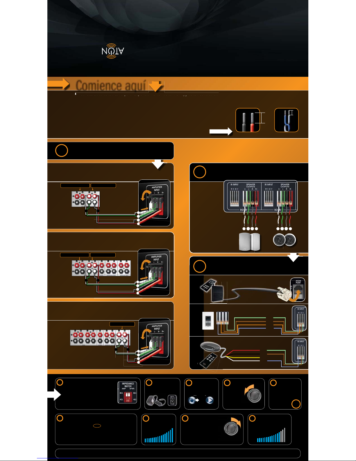
Comience aquí
ARecibidor en estéreo con "A/B"
1Elija el tipo de Receptor/Amplificador
BReceptor "Home Theater" con "A/B"
PANELES TÁCTILESRECEPTORES IR
+
+–
–
+–
+–
CReceptor "Home Theater" con "Zona 2" IR S G V
Blanco/Verde (+12V)
Marrón (Tierra)
anaranjado (Status)
Blanco/Azul (IR)
Cat5 Wire
Empálmelo al cable
Conéctelo
a las
terminales
de "Zona 2"
del parlante.
NOTA: Consulte el manual del receptor para obtener ayuda
para activar las salidas de "Zona 2" del parlante.
+
–
+
–
LR+
–
+
–
Conéctelo
a las
terminales
"B" del
parlante.
Hacia los parlantes locales Hacia la entrada de DLA
Rojo
Negro
Blanco
Amarillo (No lo conecte)
Blanco/Verde (+12V)
Marrón (Tierra)
Blanco/Azul (IR)
+
–
+
–
+
–
+
–
LR
LR
+
–
+
–
+
–
+
–
Cable del parlante
Asegúrese de
conectar el cable
positivo del parlante
a la entrada positiva
del mismo, y el
cable negativo
del parlante a la
entrada negativa
del mismo.
RJ11
Fije los conmutadores DIP de impedancia.
Conmutador DIP del amplificador:
Fíjelo en una impedancia de Receptor/Amplificador de
8 o 4 Ohms. (Consulte el manual del receptor/amplificador
para obtener información de impedancia específica)
Conmutador DIP del parlante:
Fíjelo en una impedancia media de parlante de 8 o 4 Ohms.
(Consulte el manual del parlante para obtener información de impedancia específica)
Enchufe la fuente
de alimentación del
DLA2/4/6.
Ajuste el volumen
del Receptor/
Amplificador
al nivel
más bajo.
r
Encienda el Receptor/
Amplificador y haga
funcionar una fuente de
audio (reproductor de
CD, radio, etc.).
Fuente de
alimentación
Haga funcionar una
fuente de audio
Perilla de volumen del
Receptor/Amplificador
4567
Por último, encienda cada
sala desde el panel frontal del
DLA2/4/6 y ajuste el volumen
a un nivel agradable.
12
Mientras escuche la sala encendida en
el paso anterior, ajuste lentamente el
volumen del Receptor/Amplificador
al nivel más fuerte que pueda
reproducirse en la sala sin
distorsión ni recortes. Tome nota
del nivel de volumen para usarlo
como referencia en el futuro.
n
i
a en
ente e
ado
r
o
11
Fije el Receptor/
Amplificador en
modo estéreo y
desactive cualquier
sonido envolvente
o los "Campos de
Sonido" DSP.
8
Encienda una sala
desde el panel frontal
del DLA2/4/6 y ajuste
el nivel de volumen al
máximo.
10
9
Perilla de volumen del
Receptor/Amplificador
Please consult your owner's manual for additional
installation examples, applications and safety instructions.
¡ADVERTENCIA! No conecte los parlantes al DLA2/4/6 que tenga una impedancia menor a la que su receptor/
amplificador soporta. ¡Si lo hace, corre el riesgo de recalentar y dañar tanto el DLA2/4/6 como el receptor/
amplificador! Consulte los manuales del parlante y del receptor/amplificador para obtener información de
impedancia específica.
Si está usando un Receptor con salidas de parlante "A/B":
s3ELECCIONELACONlGURACINDEPARLANTE
"B" para usar sólo los parlantes
conectados al DLA
s3ELECCIONELACONlGURACINDEPARLANTE
"A+B" para usar tanto los parlantes "A"
como los que están conectados al DLA
O BIEN
NOTA: Cuando use la configuración "A+B", el volumen del receptor tendrá que ajustarse
en conformidad.
Cuando el DLA2/4/6 no se esté usando, apague los parlantes "B" y encienda los
parlantes "A" para oír un sonido envolvente/estéreo normal.
Conéctelo
a las
terminales
"B" del
parlante.
Hacia los parlantes locales Hacia la entrada de DLA
Hacia la entrada de DLA
RECEPTOR RF
3Elija el método de control Opcional
2Conecte los parlantes
Conecte el Receptor RF
al puerto ATON
Consulte el manual del propietario para obtener ejemplos de instalación, aplicaciones e instrucciones de seguridad adicionales.
Cable del parlante
Cable del parlante
P/N 9900882 Rev: B
!


