manuals.online logo
Brands
  1. Home
  2. •
  3. Brands
  4. •
  5. ATS
  6. •
  7. Automobile Accessories
  8. •
  9. ATS Co-Pilot User manual

ATS Co-Pilot User manual

Installation Manual for 1989-1997 Ford Power Stroke v1.1
Please read all instructions before the installation of the ATS Commander
Thank you for purchasing the ATS Co-Pilot. This manual is to assist you with your installation
and operation of the unit. If you are installing the unit for a customer, pass this manual on to
your customer for future reference.
Understanding the ATS Co-Pilot
The ATS Co-Pilot is recommended for use with light duty pickup trucks with a heavy-duty
aftermarket transmission and torque converter package are installed on vehicle. While the
Commander will still function perfectly on a stock transmission, factory transmission shafts are
weak and prone to breakage. The factory torque converter clutch will also fail if applied under
high load conditions. Factory computers are programmed to disengage lockup under certain
conditions which will protect the transmissions internal components under higher load. This is
when we recommend having a heavy-duty aftermarket transmission installed on your vehicle to
prevent transmission failure. If you have a stock transmission it is recommended that you leave
your Co-Pilot in a less aggressive setting when under high load conditions. ATS Diesel
Performance sells many parts for all levels of trucks that will strengthen your transmission and
improve reliability, whether you have a stock daily driver or a fully built race truck! Give us a
call today if you feel the need to get a fully rebuilt transmission for your truck, or if you just
want to strengthen your current transmission with a few upgraded parts. Our experts can help
answer any questions you have and guide you in the right direction.
Setting up the ATS Co-Pilot module for installation
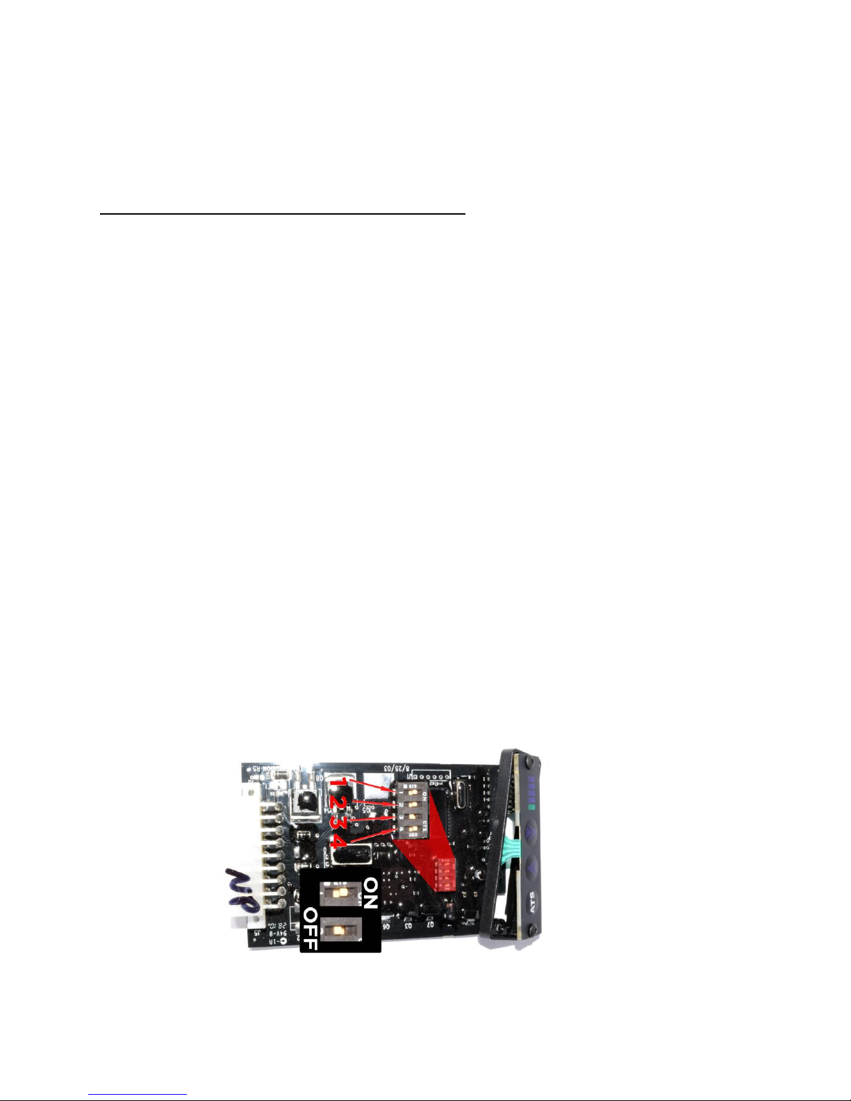
The ATS Co-Pilot will need to be set up for your vehicle and application. The Co-Pilot will
need to be disassembled to access the dip switches on the electronic board. You will need a
1/16th - inch hex (Allen wrench) to remove the face from the Co-Pilot. After the face has been
removed the electronic board can be slid out of the casing from the front. The digital face is
attached to the circuit board with a ribbon cable; do not force the board from the case. There are
four (4) switches on the circuit board; the switches allow the user to select the features desired.
The settings are listed below. When reinstalling the face on the Co-Pilot do not over tighten the
2 small screws on the face.
Dip switch selection:
---------------------------------------------------------------------------------------------------------------------------------------
Switch #1
Set to OFF position
---------------------------------------------------------------------------------------------------------------------------------------
Switch #2
Set to ON position
----------------------------------------------------------------------------------------------------------------------------------------
Switch #3 - Speed setting
On=low speed cut out
Off= Hi speed cut out
----------------------------------------------------------------------------------------------------------------------------------------
Switch #4
Set switch to ON position
---------------------------------------------------------------------------------------------------------------------------------------
We have preset your module with #1-OFF, #2-ON, #3-OFF, and #4-ON.
Co-Pilot Mounting Location
Find a convenient location to mount the Co-Pilot within reach and view of the driver. The
Commander interface must be within visual range of the driver as well as in easy reach. We
have found the ideal place to locate the module is just to the right of the driver on the lower dash
panel just above the right knee. Use the Velcro supplied to secure it to the dash. Before sticking
the Velcro to the dash use brake clean or acetone on the area the sticker will be. Run the
Co-Pilot wires that are to be wired up to the PCM (Power-train control module) and the
transmission through the firewall
Wiring The Co-Pilot For 1989-1994 models
-The Co-Pilot has several connections that need to be made in order for it to function properly.
There are several wires which are optional but still included to give the Co-Pilot a more versatile
use depending on your trucks current setup. Use the diagram below as a reference when
installing your Co-Pilot to avoid any conflicts or confusion.
NOT USED: Orange Wire (Pin 4), White Wire (PIN #5), Pink Wire (PIN #12), Purple
Wire (PIN #16) And Gray (PIN #14).
Red Wire- +12V Power – PIN #1
Locate the Red wire coming from the vehicle’s PCM Pin #37. Tap this wire with the Red
Commander wire by soldering. Shield the tap from the elements.
Black Wire- Ground (GND) – PIN #9
Locate the Black w/ White wire coming from the vehicle’s PCM Pin #60. Tap this wire with
the Black Commander wire by soldering. Shield the tap from the elements.
Yellow Wire– PCM - PIN #10 and Blue Wire– TCC - PIN #11
Locate the vehicle’s Torque Converter Clutch (TCC) wire coming from the vehicle’s
transmission. This Purple w/ Yellow stripe wire can be found at the transmission connector
(passenger side of the transmission, above the pan rail). Cut this wire and solder, or attach a butt
connector to the wire leading back to the transmission and attach a butt connector to the wire
heading into the wire loom to the vehicle’s computer (PCM). Reference the supplied wiring
schematic before cutting wire.
Connect the Yellow wire coming from the Co-Pilot to the wire that goes to the PCM. Connect
the Blue wire coming from the Co-Pilot to the wire that goes to the transmission.
Protect the connections from the elements.
Green Wire- Vehicle Speed Sensor (VSS) – PIN #17
Locate the VSS (Vehicle Speed Sensor) wire. This Gray w/ Black stripe wire can be found at
the transmission connector (passenger side of the transmission, above the pan rail). Tap by
soldering the Green Co-Pilot wire to the VSS wire and protect from elements. A poor VSS
connection is the most common wiring problem.
If at any time you would like to bypass the Co-Pilot’s operation, simply unplug the wiring
harness from the Co-Pilot Module and jumper the harness’ blue and yellow terminals
together with a paperclip.
Wiring The Co-Pilot For 1994.5-1997 models
-The Co-Pilot has several connections that need to be made in order for it to function properly.
There are several wires which are optional but still included to give the Co-Pilot a more versatile
use depending on your trucks current setup. Use the diagram below as a reference when
installing your Co-Pilot to avoid any conflicts or confusion.
NOT USED: Orange Wire (Pin 4), White Wire (PIN #5), Pink Wire (PIN #12), Purple
Wire (PIN #16) And Gray(PIN #14).
Red Wire (12volts)-Pin #1
Locate the Red wire coming from the vehicle’s PCM Pin #71. Tap this wire with the red
Co-Pilot wire by soldering. Shield the tap from the elements.
Black Wire- Ground (GND) – PIN #9
Locate the Black wire coming from the vehicle’s PCM Pin #51. Tap this wire with the black
Co-Pilot wire by soldering. Shield the tap from the elements.
Yellow Wire– PCM - PIN #10 and Blue Wire– TCC - PIN #11
Locate the vehicle’s Torque Converter Clutch (TCC) wire coming from the vehicle’s PCM to the
transmission. This Purple w/ Yellow stripe wire can be found at the PCM at pin #28. Cut this
wire and solder, or attach a butt connector to the wire leading back to the transmission and attach
a butt connector to the wire heading to the vehicles computer (PCM). Reference the supplied
wiring schematic before cutting wire.
Connect the Yellow wire coming from the Co-Pilot to the wire that goes to the PCM. Connect
the Blue wire coming from the Co-Pilot to the wire that goes to the transmission.
Protect the connections from the elements.
Green Wire- Vehicle Speed Sensor (VSS) – PIN #17
Locate the VSS (Vehicle Speed Sensor) wire. This Gray w/ Black stripe wire can be found at
the PCM at pin #58 Run the green wire from the Co-Pilot module to the VSS wire and cut off
any excess, but leave some slack. Solder the Green Co-Pilot wire to the VSS wire and protect
from elements, this is the most common install problem with wiring
Wiring The Co-Pilot For 1997 models E350 models
Red Wire (12volts)-Pin #1
Locate the Red wire coming from the vehicle’s PCM Pin #71. Tap this wire with the red
Co-Pilot wire by soldering. Shield the tap from the elements.
Black Wire- Ground (GND) – PIN #9
Locate the Black wire coming from the vehicle’s PCM Pin #51. Tap this wire with the black
Co-Pilot wire by soldering. Shield the tap from the elements.
Green Wire- Vehicle Speed Sensor (VSS) – PIN #17
Locate the VSS (Vehicle Speed Sensor) wire. This Gray w/ Black stripe wire can be found at
the PCM at pin #58 Run the green wire from the Co-Pilot module to the VSS wire and cut off
any excess, but leave some slack. Solder the Green Co-Pilot wire to the VSS wire and protect
from elements, this is the most common install problem with wiring
Yellow Wire – PCM – PIN #10 and Blue Wire– TCC - PIN #11
Locate the vehicle’s Torque Converter Clutch (TCC) wire coming from the vehicle’s PCM to the
transmission. This Purple w/ Yellow stripe can be found at the PCM at pin #54. Cut this wire
and solder, or attach a butt connector to the wire leading back to the transmission and attach a
butt connector to the wire heading to the vehicles computer (PCM). Reference the supplied
wiring schematic before cutting wire.
Connect the Yellow wire coming from the Co-Pilot to the wire that goes to the PCM. Connect
the Blue wire coming from the Co-Pilot to the wire that goes to the transmission.
Protect the connections from the elements.
Troubleshooting
If you experience problems after installation, there is a simple test to help diagnose the problem.
Simply unplug the wiring harness from the back of the Commander module and put a bent
paperclip into blue and yellow terminals of the harness’ plug (jumper the blue and yellow
together). This reconnects the wire that you cut at the transmission plug and bypasses the
Commander completely.

Other manuals for Co-Pilot

2

Other ATS Automobile Accessories manuals

ATS Co-Pilot User manual

ATS

ATS Co-Pilot User manual

ATS Co-Pilot User manual

ATS

ATS Co-Pilot User manual

ATS 652-2201 User manual

ATS

ATS 652-2201 User manual

ATS 601-050 Series User manual

ATS

ATS 601-050 Series User manual

ATS Water boy User manual

ATS

ATS Water boy User manual

ATS 664-0030 User manual

ATS

ATS 664-0030 User manual

ATS L6108A User manual

ATS

ATS L6108A User manual

Popular Automobile Accessories manuals by other brands

rough country RC-O5 quick start guide

rough country

rough country RC-O5 quick start guide

Sena SLR user guide

Sena

Sena SLR user guide

Vision X Cannon CTL-CPZ6 Series installation instructions

Vision X

Vision X Cannon CTL-CPZ6 Series installation instructions

Directed DS3+ installation guide

Directed

Directed DS3+ installation guide

Ranger design 16-UCT66 installation guide

Ranger design

Ranger design 16-UCT66 installation guide

iArmor IARMOR EDGE IA-N179&N208 quick start guide

iArmor

iArmor IARMOR EDGE IA-N179&N208 quick start guide

Car-Interface CI-RL4-SY3-R5 manual

Car-Interface

Car-Interface CI-RL4-SY3-R5 manual

PE Racing Pedalbox Assembly Manual & Installation Instructions

PE Racing

PE Racing Pedalbox Assembly Manual & Installation Instructions

Westin 50 Series instructions

Westin

Westin 50 Series instructions

v.link VL2-DVD800 manual

v.link

v.link VL2-DVD800 manual

v.LOGiC 27-V5-NBT manual

v.LOGiC

v.LOGiC 27-V5-NBT manual

Kogan KAHUDQ7GPSA user manual

Kogan

Kogan KAHUDQ7GPSA user manual

STO N SHO SNS 20 Installation procedures

STO N SHO

STO N SHO SNS 20 Installation procedures

GYS GYSFLASH 1.12 manual

GYS

GYS GYSFLASH 1.12 manual

DICE MediaBridge user guide

DICE

DICE MediaBridge user guide

AUTOTECH 10.525.1028GK-1028K installation instructions

AUTOTECH

AUTOTECH 10.525.1028GK-1028K installation instructions

BEST BUY essentials BE-MVQ3AC1B23 quick start guide

BEST BUY essentials

BEST BUY essentials BE-MVQ3AC1B23 quick start guide

Nokia CK-600 Product sheet

Nokia

Nokia CK-600 Product sheet

manuals.online logo
manuals.online logoBrands
  • About & Mission
  • Contact us
  • Privacy Policy
  • Terms and Conditions

Copyright 2025 Manuals.Online. All Rights Reserved.