ATS Omega Implant Manual

USER MANUAL Rev 1 April 2017
Omega Implant
Page 1 of 16
ATS DENTAL srl – 51030 Serravalle Pistoiese – Italy – www.atsdental.it
REF Model
AOMG300DL “plus”
“Omega Implant Autoclavable Motor + DeLuxe Pedal + L.E.D. Light”
OMG300DL
“Omega Implant NOT Autoclavable Motor +
DeLuxe Pedal”
OMG300S
“Omega Implant NOT Autoclavable Motor + Standard Pedal”
OMG300E
“Omega Implant NOT Autoclavable Motor + Easy Pedal”
Refer to the “REF” on the bottom to identify the model

USER MANUAL Rev 1 April 2017
Omega Implant
Page 2 of 16
ATS DENTAL srl – 51030 Serravalle Pistoiese – Italy – www.atsdental.it
1. SYMBOLS
0425 EEC 93/42
Risk of electric shock
Follow Instructions for use
Disposal Information
Type B appliance V
Supply Voltage
Manufacturer REF Reference
Type Device type
SN
YY = year manufactured
ZZZ = Ref
XXXX = Serial Number
Web user manual
Class I Equipment
Mode: continuous operation
with intermittent load
Read this instruction booklet carefully before installing and using the machine. In this way, you will obtain the best possible results
and maximum operating safety. This booklet must be kept with the apparatus in case of sale or transfer to another user.
2. NOTICE/WARNING
DM Classification 93/42/EEC (Annex IX) CLASS IIa rule 9
Classification CEI EN 60601
Class I Equipment
Type BF Applied Part
Ordinary Equipment - degree of protection against ingress of water
Not suitable for use in the presence of a flammable anesthetic mixture with air or with oxygen or nitrous oxide.
2.1 Purpose – Proper use:
OMEGA IMPLANT is intended only for use in the field of dentistry, for surgery to expose and dissect oral tissue structures (such as the
periodontal gap, gingival, bone, the jaw, extractions and implantations). The product may not be used for a purpose for which it was not
intended.
"Proper use" includes following all the instructions for use and ensuring that all inspections
and service tasks are performed.
The overarching guidelines and/or national laws, national regulations and the rules of technology applicable to medical devices for start-
up and use of the ATS DENTAL product for the intended purpose are to be applied and complied with.
The user must ensure that that the unit works properly and is in a satisfactory condition before each use.
During use, national legal regulations must be observed, in particular:
the applicable health and safety regulations
the applicable accident prevention regulations
Users have a duty to:
Only use equipment that is operating correctly
To protect himself, the patient and third parties from danger
To avoid contamination from the product
Device users:
Use of the OMEGA IMPLANT is restricted solely to qualified, trained and competent dental health practitioners in the normal
context of their work.
If you have received this device by error, please contact the supplier so that it can be removed.
User population:

USER MANUAL Rev 1 April 2017
Omega Implant
Page 3 of 16
ATS DENTAL srl – 51030 Serravalle Pistoiese – Italy – www.atsdental.it
This medical device can only be used by skilled and capable qualified dental health professionals, as a part of their normal activities. The
user must have a perfect practical knowledge of the accepted dental rules and practices in compliance with established data of the
science, and of the principles of medical hygiene such as the cleaning, disinfection and sterilisation of medical devices, and must observe
those rules, practices and principles.
This medical device can be used irrespectively of specific (adult) user details, such as weight, age, height, gender and nationality. The
user must wear gloves. The user is not the patient.
Users must not have any of the following ailments:
Eye problems, unless the latter are appropriately corrected.
Disability of the upper limbs (correct holding of a rotary handpiece) or of the lower limbs (operation of a control pedal).
Ear problems (use of audible signals, depending on the equipment).
Memory or concentration problems (settings, sequences or medical procedures, etc.).
Specific training for users:
No specific training other than the original professional training is required in order to use this medical equipment.
Patient population:
This medical device is intended for use on the following patient population: children, teenagers, adults and elderly people.
This medical device can be used irrespectively of specific patient details such as weight (except for children), age, height, gender and
nationality. The use of this medical device is prohibited on the following patient population: infants, pregnant or breastfeeding women,
patients with medical complications, allergic patients, patients with a clinical zone that is not suitable for the treatment. The patient
must be calm, relaxed, still, and ideally lying on a dental chair.
Body areas or types of tissue treated:
The medical care can only be carried out in the patient's oral environment.
Principle of operation of the medical device:
An electrical signal output by the medical device is supplied to the micromotor (dental or oral surgery). The micromotor is connected to
medical device by a lead.
The micromotor is equipped with a rotary instrument holder onto which a tool (drill, burs, etc.) is attached. The rotation of the
micromotor activates the tool.
Part(s) applied:
Rotary instrument holder. Tool (drill, bur, etc.).
Utilization:
The medical device must not be used above an altitude of 2,000 metres (6,500 feet).
The medical device is not restricted by a limited number of utilisations.
Electrical connection:
Your device must be connected to the electric power supply by a certified dental installation technician. The electric supply to
which the device is connected must comply with the standards in force in your country.
Using the device:
Do not use the device if it appears to be damaged or faulty.
Turn the device off before unplugging the power cord.
To unplug the power cord, grip the external transformer and hold the wall socket.
Never use any other irrigation solution containers than those intended for suspension from the supplied brackets.
The device must only be used with bottles or bags of physiological saline.
The capacity of the irrigation solution containers used must not exceed one liter.
When the device is not to be used for a long period of time, unplug the device from the electric supply.
Do not move the device during use.
Do not insert anything inside the motor.
The “micromotor” is supplied Non-Sterile!
Use only power cord provided
Use for intended purposes only. Failure to observe the operating instructions may result in the patient or user suffering serious
injury. Before using this product, make sure that you have studied and understood the operating instructions.
Do not install where there is a risk of an explosion. The Systems are not intended for operation in the presence of flammable
anesthetics or gases.
Do not disassemble or alter the System motor, console, or footswitch.
Connect mains power cable to a properly outlet only.
Never touch drills, burs, or other handpiece tips when they are still rotating.
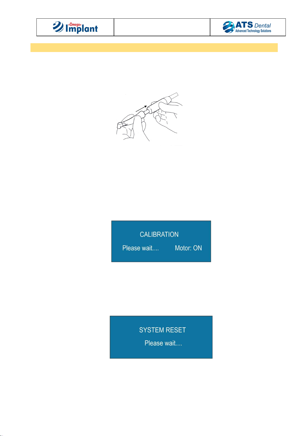
Handpiece should only be attached when the motor has stopped running.
Environment:
Do not cover the device or obstruct the ventilation vents.
Do not immerse the device in liquid, and do not use it outdoors.
Do not tilt the device at an angle greater than 5°.
Do not place the device near a heat source.
Make sure that the cords are not in a traffic path.
The device should be stored in its original packaging in a safe place.
Do not expose the device to water vapor, or splashes.
The device is not designed to work near ionizing radiation.

USER MANUAL Rev 1 April 2017
Omega Implant
Page 4 of 16
ATS DENTAL srl – 51030 Serravalle Pistoiese – Italy – www.atsdental.it
Do not insert metal objects into the device (risk of electric shock, short-circuit or emission of hazardous substances).
Maintenance:
Before and after each use, your device must be disinfected with products recommended by the manufacturer.
Before each procedure, it is essential to make sure that the accessories to be used have been cleaned, disinfected. Do not use
agents containing phenol, per acetic acid, peroxide and other agents that break up the oxygen.
DO NOT (for any reason), lubricate the micromotor. After lubricating the handpiece, ensure that the lubricant does not
penetrate into the micromotor.
Accessories:
The device can only accept accessories distributed by ATS DENTAL for the particular use for which they are intended.
Use of accessories from other manufacturers is a potential hazard for you or your patients.
Repair:
Do not repair or modify the device without prior authorization from the manufacturer.
In the case of a fault, contact the supplier of your device. Do not use unauthorized repairers, who might make your device
dangerous for you and your patients.
If you have any doubt, contact an approved dealer or our customer support department:
Information concerning the accuracy and precision of this product may be obtained upon request by contacting:
ATS Dental srl Via Vecchia Provinciale Lucchese,49/F Serravalle Pistoiese – Italy
Tel: +39 0573 518137 [email protected]
2.2 Electromagnetic Interferences
To avoid possible risks of electromagnetic interferences do not use other electro-medical instruments of similar nature near
OMEGA IMPLANT. The unit complies with the current normative electromagnetic radiation law.
This device has been tested and found to comply with the emissions requirements of IEC 60601-1-2. These requirements
provide reasonable protection against harmful electromagnetic interference in a typical medical installation. However, high
levels of radio-frequency (RF) emissions from electrical devices, such as cellular phones, may disrupt the performance of this
device. To mitigate disruptive electromagnetic interference, position this device away from RF transmitters and other sources
of electromagnetic energy.
The device complies with applicable electromagnetic compatibility standards. The user should nevertheless ensure that any
potential electromagnetic interference does not cause an additional risk (presence of radiofrequency emitters, electronic
devices, etc.). Interference may occur when used on patients with cardiac pacemakers. This system emits electromagnetic
fields, which means there are some potential risks. The malfunctioning of implantable devices such as cardiac pacemakers and
ICDs (implantable cardioverter defibrillator) is possible. Ask patients and users if they have an implanted device before using
this product. Explain the circumstances to them. Weight the risks and benefits and contact your patient's cardiologist or
appropriate qualified healthcare professional prior to performing the treatment Keep this product away from implanted
devices Make appropriate emergency provisions and take immediate action if patients become ill. Symptom including a raised
heartbeat, irregular pulse, and dizziness may signal problems with a cardiac pacemaker or ICD.
2.3 Responsibility of the manufacturer
The ATS Dental can only accept responsibility for the safety, reliability and performance of the OMEGA IMPLANT when there is
compliance with the following directions:
• The OMEGA IMPLANT must be used in accordance with these Instructions for Use.
• The OMEGA IMPLANT has no components which can be repaired by the user.
Assembly, modifications or repairs must only be undertaken by an authorized service organization.
• Unauthorized opening of the equipment invalidates all claims under warranty and any other claims.
• Use on electrical circuit complying with the terms of regulation CEI 64-8 section 710.
• Use of components which are not original or different from those specified in the paragraph PACKAGE CONTENTS.
2.4 Disposal of the equipment
Please observe the regulations applicable in your country.
Within the European Economic Community, Council Directive 2002/96/EU (WEEE) requires environmentally sound recycling/disposal of
electrical and electronic devices. Your product is marked with the adjacent symbol. Disposal of your product with domestic refuse is not
compatible with the objectives of environmentally sound recycling/disposal. The black bar underneath the "garbage can" symbol means
that it was put into circulation after Aug. 13, 2005. (see EN 50419:2005) Please note that this product is subject to Council Directive
2002/96/EU (WEEE) and the applicable national law of your country and must be recycled or disposed of in an environmentally sound
manner. Please contact your dealer if final disposal of your product is required.

USER MANUAL Rev 1 April 2017
Omega Implant
Page 5 of 16
ATS DENTAL srl – 51030 Serravalle Pistoiese – Italy – www.atsdental.it
3. PACKAGE CONTENTS
REF Model
AOMG300DL
“Omega Implant Autoclavable Motor + DeLuxe Pedal + L.E.D. Light”
Electronic Control Console
Micromotor Assembly Autoclavable
Pedal “DeLuxe”
Irrigation Bag Hanger Rod
Peristaltic Pump Tubing
C- Power Supply
L.E.D. Light
OMG300DL
“Omega Implant NOT Autoclavable Motor + DeLuxe Pedal”
Electronic Control Console
Micromotor Assembly NOT Autoclavable
Pedal “DeLuxe”
Irrigation Bag Hanger Rod
Peristaltic Pump Tubing
C- Power Supply
OMG300S
“Omega Implant NOT Autoclavable Motor + Standard Pedal”
Electronic Control Console
Micromotor Assembly NOT Autoclavable
Pedal “Standard”
Irrigation Bag Hanger Rod
Peristaltic Pump Tubing
C- Power Supply
OMG300S
“Omega Implant
NOT
Au
toclavable Motor + Easy Pedal”
Electronic Control Console
Micromotor Assembly NOT Autoclavable
Pedal “Easy”
Irrigation Bag Hanger Rod
Peristaltic Pump Tubing
C- Power Supply
Refer to the “REF” on the bottom to identify the model

USER MANUAL Rev 1 April 2017
Omega Implant
Page 6 of 16
ATS DENTAL srl – 51030 Serravalle Pistoiese – Italy – www.atsdental.it
4. SET UP
4.1 Environmental and transport conditions:
Internal use. Altitude lower than 3000 m (10,000 ft).
Temperature : 18°C / 40°C (64°F / 104°F).
Relative Humidity: < 80% (non-condensing).
4.2 Safety precautions:
a. Do not insert anything inside the motor
b. The “Motor” is supplied Non-Sterile.
c. Use only power cord as described in the section Package Contents
d. Use for intended purposes only. Failure to observe the operating instructions may result in the patient or user suffering
serious injury. Before using this product, make sure that you have studied and understood the operating instructions
e. Do not install where there is a risk of an explosion. The Systems are not intended for operation in the presence of
flammable anesthetics or gases
f. Do not disassemble or alter the System motor, console, or foot switch.
g. Connect mains power cable to a properly grounded outlet only.
h. Never touch drills, burs, or other handpiece tips when they are still rotating.
i. Handpiece should only be attached when the motor has stopped running
4.3 Setting up the unit:
1. Cut the adhesive tape and open the suitcase. Remove the unit and its accessories from their original packaging and place
on a flat surface. Not install near heat sources, direct or indirect.
2. Verify the contents of the box according to the section “PACKAGE CONTENTS”
3. Do not kink the motor hose since it may damage it.
4. All accessories are supplied non-sterile except for tubing.
5. The serial number on the Unit’s rear panel must be the same as the one on transport documents.
6. Allow at least 150 mm free space around the unit for cooling ventilation.
Damage in Transit
If the packaging is visibly damaged on delivery, please proceed as follows:
a. The recipient of the package must record the loss or damage on the delivery receipt. The recipient and the representative of the
shipping company must sign this delivery receipt. Without this evidence, the recipient will not be able to assert a claim for
damages against the shipping company.
b. Leave the product and packaging in the condition in which you received it and do not use the product.
If the product is damaged but there was no discernable damage to the packaging upon delivery, proceed as follows:
a. Report the damage immediately or at least 7 days after the delivery to the delivery company.
b. Leave the product and packaging in the condition in which you received it and do not use a damaged product
4.4 Assembling the unit
Micro Motor connection
Connect the micro motor into the receptacle on the front of the central unit
Connect the Contrangle to the Micro Motor.
Only for “REF” AOMG300DL press the button on the rear side to switch on LED Light
Place the Micro Motor on the motor holder.
Foot Pedal connection
Connect the foot pedal into the receptacle on the front of the central unit
Place the foot pedal on the ground.
While inserting the plug, align the guide on the connector in an upright position to fit into the corresponding female guide on the OMEGA
IMPLANT. Connectors have a spring retention system to help avoid accidentally disconnecting the unit's cords and cables.

USER MANUAL Rev 1 April 2017
Omega Implant
Page 7 of 16
ATS DENTAL srl – 51030 Serravalle Pistoiese – Italy – www.atsdental.it
5. CONTROL PANEL FUNCTIONS
1500/2000
1. Motor ON/OFF
2. Pump ON/OFF
3. Adjust Pump Flow
4. Allows the user to store and quickly access up to 5 different “Programs”
5. Torque adjust.
6. Speed Increase/Decrease.
7. Handpiece ratio selector.
8. Forward/Reverse Selector
9. Calibrate handpiece.
6. CONSOLE BACK
1
3
34
2
2
REF: AOMG300DLREF: OMG300DL - OMG300S - OMG300E
1. Switch ON/OFF LED Light
2. PUMP
3. MAIN POWER On/Off
4. Power Cord In
1. PUMP
2. I POWER On/OffMAIN
3.. Power Cord In
1

USER MANUAL Rev 1 April 2017
Omega Implant
Page 8 of 16
ATS DENTAL srl – 51030 Serravalle Pistoiese – Italy – www.atsdental.it
7. PEDAL (FOOT CONTROL OPERATION)
“REF”: AOMG300DL – OMG300DL
“DELUXE”
The left-hand button allows user to
change the value of the coolant pump as
well as the key “flow” on the keyboard.
The central up button allows user to
change the programs as well as the key “P
- programs” on the keyboard.
The right hand button allows user to
switch between forward and reverse
motor rotation (when in reverse, console
will emit a beeping tone), as well as the
key “Fwd/Rev” on the keyboard.
The central down button allows user to
control up to the pre-selected maximum
speed and switch on the pump if enabled.
“REF”: OMG300S
“STANDARD”
“REF”: OMG300E
“EASY”
It allows user to control up to the pre-
selected maximum speed and switch on
the pump if enabled.
8. IRRIGATION TUBE SETUP
1. Open the pump
2. Insert the rotor of the pump inside the pump
3. Close the pump
4. Hang the bottle or bag of physiological saline from the bracket
5. Insert the irrigation line perforating into the bottle or bag of physiological saline
6. Connect the end of irrigation line to the contrangle.
NB: Use only ATS DENTAL Tube. Do not run the pump without tube.
Do not use coolant reservoirs that can hold more than 1 liter. Ensure that the device is standing securely. Use transparent coolant
reservoirs

USER MANUAL Rev 1 April 2017
Omega Implant
Page 9 of 16
ATS DENTAL srl – 51030 Serravalle Pistoiese – Italy – www.atsdental.it
9. Use
After the unit has been set up and the user has become familiar with the System’s control panel functions:
1. Attach the appropriate "E-Type" handpiece to the motor. It can be used with most surgical contra-angles without internal
light or spray on the market. Use only handpiece that conform to ISO 3964. Change the handpiece and angle piece only when
the motor not running
1. Insert bag hanger rod into socket on the top of the console.
2. Attach the motor to the connector on the right side (facing the unit) on the front panel.
3. Attach the foot control to the connector (gray color) on the front panel.
4. Install irrigation tubing into pump on the rear panel. Use only tubing as described in “Irrigation Tube Set Up”.
5. Switch on (on the rear panel) OMEGA IMPLANT
6. Only with “REF”: AOMG300DL, in case, switch on (on the rear panel) the LED Light
In every program Programs [ 1 to 5] are set the same parameters by the manufacturer.
Perform torque calibration, press “Calibration” key on front panel while holding the motor. This function checks the handpiece
mechanical inertia, to off-set this value.
This operation will take a few seconds, the drill will run at different speed, and the display will show as follow:
The drill must not be engaged in any operation when this function is performed.
Calibration should be done before each surgical session or anytime the handpiece is changed or lubricated.
OMEGA IMPLANT will store the operative parameters for each “program” as soon as the user sets them. They will be maintained in the
memory even if the central unit is switched off. For each “program” it is possible to set: speed, torque, ratio, direction of rotation and
flow. To reset the parameters of the manufacturer (System Reset), press the “PUMP ON/OFF” key while the unit is switched on.
The display will show as follow:

USER MANUAL Rev 1 April 2017
Omega Implant
Page 10 of 16
ATS DENTAL srl – 51030 Serravalle Pistoiese – Italy – www.atsdental.it
9.1 Programming the unit
RATIO: Sets handpiece reduction ratio. See the available reduction ratio in the following table:
1:1 16:1 20:1 24:1 32:1 64:1 80:1
SPEED +/-: Sets motor rotation speed (value in rpm). Speed values depend on contra-angle reduction rate.
“REF” AOMG300DL: max speed is 2000 rpm with 20:1 contrangle. Min speed is 20 rpm with 20:1 contrangle
“REF” OMG300DL – OMG300DL – OMG300S – OMG300E : max speed is: 1500 rpm with 20:1 contrangle. Min speed is 20 rpm with 20:1
contrangle
TORQUE +/- : increases or decreases the torque values. Torque values are in Ncm and depend on contra-angle reduction rate.
“REF” AOMG300DL: max torque is 72 Ncm with 20:1 contrangle.
“REF” OMG300DL – OMG300DL – OMG300S – OMG300E: max torque is 51 Ncm with 20:1 contrangle.
Pay special attention to use the same ratio of the handpiece. Torque accuracy is guarantee only with 20:1 Contrangle correctly
maintained. The torque values are only for handpieces that operate properly. Micro motor stops when set torque is reached. The torque
value in counterclockwise rotation is always = Max Ncm
FLOW: Selects variable irrigation pump flow rate. See the following table:
0 = no irrigation MIN MED MAX
REVERSE: Switch between forward and reverse motor rotation (when in reverse, console will emit a beeping tone).
MOTOR ON/OFF: Switches motor ON and OFF (if enabled).
PUMP ON/OFF: Switches pump ON and OFF (if enabled).
10. Cleaning and Sterilization
Unplug the main unit from power source before cleaning or disinfecting. Do not use directly on liquids and sprays. Never immerse the
unit or its parts in liquid.
External surface of the console may be cleaned with a damp cloth or disinfectant wipe. The housing is not waterproof. Do not use
ultrasonic or steam sterilizers. External surface of the micro motor may be cleaned with a damp cloth or disinfectant wipe. Do not place
micro motor in ultrasonic sterilizers. Motor Holder and Irrigation Bag Hanger Rod may be cleaned with a damp cloth or disinfectant wipe.
The exterior of the foot controls may be cleaned by wiping with a soft cloth moistened with mild detergent or disinfecting solution.
WHAT CAN BE STERILIZED : STERILIZATION METHOD :
Sterilization with steam or chemical vapor
Sterilization time : 18 minutes at 134°C/2 bar.
Do not exceed 138° C or 275° F
Cooling time : 2 hours
Working temperature : 40°C
Max sterilization cycles: 500.
Do not submerge in any solutions
Do not use ultrasonic cleaners
Do not sterilize with Ethylene Oxide
“REF” AOMG300DL
Micromotor
Assembly
Motor Holder
Irrigation Bag
Hanger Rod
“REF”
OMG300DL - OMG300S –
OMG300E
Motor Holder
Irrigation Bag
Hanger Rod
When treating patients who may have an acute, critical infectious disease, be sure to observe the hygienic measures cited in applicable
publications and reports. If possible, use suitable disposable products to avoid the transmission of critical pathogens. These protect the
user, the patient and all participants in the surgery. A microbiologically appropriate coolant liquid must be used. Only use prescribed
isotonic saline solution NaCl 0.9 (identified as an infusion solution; follow the instructions on the package insert) for cooling and
spraying wounds. Not all autoclaves can reach 134° C. Not all autoclaves draw a pre-vacuum. Please refer to your autoclave
manufacturer for specific sterilization instructions.

USER MANUAL Rev 1 April 2017
Omega Implant
Page 11 of 16
ATS DENTAL srl – 51030 Serravalle Pistoiese – Italy – www.atsdental.it
11.Maintenance
The micro motor cable has limited durability and is considered a consumable product. The durability of the cable is largely dependent
upon use and treatment, i.e., handling, reprocessing and frequency of use.
Caution must be exercised when connecting or disconnecting the micro motor and foot control cable from the device to avoid damage
to the cable.
Periodically inspect the micro motor cord for damage prior to use. If there is damage noted, contact the Manufacturer.
LUBRICATING:
- Do not oil or lubricate the micro motor.
RUBBER O-RING:
- If necessary, substitute. Contact the Manufacturer
1.Do not attempt to disassemble the motor or motor connector.
2.Do not oil or lubricate the motor.
3. Do not attach a hand piece to the motor while the motor is running.
4.Do not bend motor cord sharply.
- The Micro motor is sensitive to shock. Do not drop or impact micro motor against hard surface
Failure to comply with any of the above instructions may void your warranty
12.TECHNICAL DATA
Manufacturer ATS Dental – Pistoia – Italy Nominal Power 100 VA
Model OMEGA IMPLANT Frequency 50/60 Hz
Dimensions 185x160x100 Protection Class 1
Materials ABS Type BF
Micro motor Brushless 40000/30000 Class MD IIa rule 9 in Annex IX 93/42/EEC
Noise < 65 dBA Console IP21
Supply Voltage 24-30 VDC Micro motor
and Pedals
IP21
Not suitable for use in presence of flammable anesthetics or oxygen.
Conditions of use: Temp +18°C/+40°C (+64°F/+140°F) RH < 80%
Shipping and Storage conditions: Temp +5°C/+65°C (+41°F/+149°F) RH < 20-95% non condensing.
Life of the device: When used as prescribed = 5 years. No warranty claim may be made in the event that the failure happen sooner
or later than indicated, because of the frequency of use, sterilization and maintenance.

USER MANUAL Rev 1 April 2017
Omega Implant
Page 12 of 16
ATS DENTAL srl – 51030 Serravalle Pistoiese – Italy – www.atsdental.it
14.”TROUBLESHOOTING”
Problem: The central unit does not switch on.
Possible cause
Solution
•Power cord not connected properly Make sure the power cord is properly plugged into the electrical outlet and the
connector on the back of the unit.
•Unit has not been switched on. Check the back of the unit to see that the On button has been pressed.
•Broken connections inside.
• Transformer damaged.
• PCB faulty.
• Filter supply defective.
• Power interrupted.
Immediately discontinue use of
the device and contact your distributor, service center,
or the manufacturer directly.
Problem: The display is not working properly
Possible cause
Solution
•Possible interference. Check to see if the central unit has been positioned too close to another
electrical device
which can cause interference. In this case, move the interfering electrical device further
away from the central unit.
•Broken connections inside.
•Display damaged.
•PCB damaged.
If you cannot find the cause of the malfunction,
immediately discontinue use of the
device and contact dealer, the authorized service center, or the manufacturer directly.
Problem: The keyboard is not working properly
Possible cause
Solution
•Keyboard damaged.
•Broken connections inside.
Attempt to change parameters by using the foot pedal.
Contact your distributor, service center, or the manufacturer directly.
Problem: The motor doesn’t work
Possible cause
Solution
• Micro motor cable not connected properly Check to see that the micro motor cable
is plugged into the connector on the front right
of the central unit, disconnect and reconnect
•Contrangle defective or not properly
calibrated.
Check the integrity of the Contrangle. Remove the Contrangle and perform calibration.
•Foot pedal damaged. Attempt to start the Micro Motor by using the [Motor ON/OFF button]
on the central
unit
keyboard. If unit does not turn on, contact dealer, the authorized service center, or
the manufacturer directly.
•PCB damaged.
•Motor damaged.
•Connector pins and/or cable damaged.
Immediately discontinue use of the device and contact dealer, the authorized service
center, or the manufacturer directly.
Problem: The motor stops suddenly
Possible cause
Solution
•Keyboard and/or foot pedal damaged Try to turn off the motor by pressing the [Motor ON/OFF] button on the keyboard or
by using the foot pedal.
If the motor will not turn off, immediately discontinue use of the device and contact
dealer, the authorized service center, or the manufacturer directly.
•Broken connections inside.
•PCB damaged
Immediately discontinue use of the device and contact dealer, the authorized service
center, or the manufacturer directly.
Problem: The pump is not working property
Possible cause
Solution
•Tube not correctly inserted
•Tube damaged.
To verify the proper tube connection follow the instructions on this DFU
Check for damage along the tube, kinks, partial occlusions, etc. Arrange for immediate
replacement of the tube.
Problem: The pump stops suddenly
Possible cause
Solution
•Pump damaged/blocked.
•PCB damaged.
Immediately discontinue use of the device and contact dealer, the authorized service
center, or the manufacturer directly.

USER MANUAL Rev 1 April 2017
Omega Implant
Page 13 of 16
ATS DENTAL srl – 51030 Serravalle Pistoiese – Italy – www.atsdental.it
15. ACCOMPANYING DOCUMENTS
Electromagnetic emissions:
OMEGA IMPLANT is intended for use in the electromagnetic environment specified below. The OMEGA IMPLANT should only be used
in such an environment.
RF emissions
CISPR 11
Group 1 OMEGA IMPLANT uses RF energy only for its internal function. Therefore, its RF
emissions are very low and are not likely to cause any interference in nearby
electronic equipment.
RF emissions
CISPR 11
Class B
OMEGA IMPLANT is suitable for use in all establishment including domestic
establishments and those directly connected to the public low-voltage power supply.
Harmonic emissions
IEC 61000-3-2
Class A
Conforms
Voltage fluctuation/ flicker
emissions
IEC 61000-3-3
Conforms
Electromagnetic Immunity:
OMEGA IMPLANT is intended for use in the electromagnetic environment specified below. The OMEGA IMPLANT should only be used
in such an environment.
Immunity test Test level
EN 60601-1-2
Compliance level Electromagnetic environment - guidance
Electrostatic discharge
(ESD) EN61000-4-2
6kV contact
8kV air 6kV
8kV
Floor should be wood, concrete or ceramic tile. If
floor are covered with synthetic material, the
relative humidity should be at least 30%
Burst/Fast transient
EN 61000-4-4
2kV for power supply
lines
2kV for power supply
lines
Quality of the Main power source should be that of a
typical commercial or hospital environment
Surge
EN 61000-4-5
1kV differential mode
2kV common mode
1kV differential mode
2kV common mode
Quality of the Main power source should be that of a
typical commercial or hospital environment
Immunity test Test level
ICE 60601
Compliance level Electromagnetic environment - guidance
Voltage dips, short
interruptions and
voltage variation on
power supply input
lines.
EN 61100-4-11
5%Ut
(95% dip in Ut) for 0,5
cycle
40% Ut
(60% dip in Uv) for 5 cycle
70% Ut
(30% dip in Ut) per 25
cycle
5% Ut
(95% dip in Ut) for 5 sec
5%Ut
(95% dip in Ut) for 0,5
cycle
40% Ut
(60% dip in Uv) for 5
cycle
70% Ut
(30% dip in Ut) per 25
cycle
5% Ut
(95% dip in Ut) for 5
sec
Quality of the Main power source should be that of a
typical commercial or hospital environment If the
user of the OMEGA IMPLANT requires continued
operation during power main interruptions, it is
recommended than the OMEGA IMPLANT be
powered from an uninterruptible power supply or
battery.
Power frequency
(50/60 Hz)
magnetic field
EN 61100-4-8
3A/m 3A/m
Power frequency magnetic fields should be at a
typical commercial or hospital establishment level.
OMEGA IMPLANT is intended for use in the electromagnetic environment specified below. The OMEGA IMPLANT should only be used
in such an environment.

USER MANUAL Rev 1 April 2017
Omega Implant
Page 14 of 16
ATS DENTAL srl – 51030 Serravalle Pistoiese – Italy – www.atsdental.it
Immunity Test Test level
IEC 60601-1-2
Compliance level Electromagnetic Environment - Guidance
Conducted RF
EN 61000-4-6
Radiated RF
IEC 61000-4-3
3 Veff from 150KHz to
80MHz
3 Veff from 80MHz to
2.5GHz
3 Veff from 150KHz
to 80MHz
3 Veff from 80MHz
to 2.5GHz
Portable and mobile RF communication equipment
should be used no closer to any part of the OMEGA
IMPLANT, including cables, than the recommended
separation distance calculated from the equation
applicable to the frequency of the transmitter.
Recommended separation distance
d = 1,2P from 150KHz to 80MHz
d = 1,2P from 80MHz to 800MHz
d = 2,3P from 800MHz to 2.5GHz
where P is the maximum output power rating of the
transmitter in watts (w) according to the transmitter
manufacturer and recommended separation distance in
metres (m).
Field strengths from fixed RF transmitter, as determined by an electromagnetic site survey a should be less than the compliance
level in each frequency range b. Interference may occur in the proximity of equipment marked with the following symbol:
Recommended separation distance between portable and mobile RF communications equipment and the OMEGA IMPLANT
The OMEGA IMPLANT is intended for use in an electromagnetic environment in which radiated RF disturbances are controlled. The
customer or the user of the OMEGA IMPLANT can help prevent electromagnetic interference by maintaining a minimum distance
between portable and mobile RF communications equipment (transmitters) and the OMEGA IMPLANT as recommended below,
according to the maximum output power of the communications equipment.
Rated maximum
output power of
transmitter (W)
Separation distance according in frequency of transmitter (m)
From 150kHz to 80MHz
d= 1,2P
From 80MHz to
800MHz
d= 1.2P
From 800MHz to 2,5GHz
d= 2,3P
0,01 0,12 0,12 0,23
0,1 0,38 0,38 0,73
1 1,2 1,2 2,3
10 3,8 3,8 7,3
100 12 12 23
For transmitters rated at a maximum output power not listed above, the recommended separation distance (D) in metres (m) can be
estimated using the equation applicable to the frequency of the transmitter, where (P) is the maximum output power rating of the
transmitter in watts (W) according to the transmitter manufacturer.

USER MANUAL Rev 1 April 2017
Omega Implant
Page 15 of 16
ATS DENTAL srl – 51030 Serravalle Pistoiese – Italy – www.atsdental.it
NOTE

USER MANUAL Rev 1 April 2017
Omega Implant
Page 16 of 16
ATS DENTAL srl – 51030 Serravalle Pistoiese – Italy – www.atsdental.it
Manufacturer
For more information, contact:.
ATS DENTAL srl
Via Vecchia Prov.le Lucchese, 49
51030 Serravalle Pistoiese
Italy
+39 0573 518137
Note: the instructions above have been validated by the manufacturer of the device as suitable for preparing the
device for reuse.
The proper implementation of the preparation process, as well as achieving the desired result, are full responsibility
of the person performing the operation.
ATS DENTAL SRL reserves the right to modify the present DFU without prior notice.
Via Vecchia Provinciale Lucchese, 49/F - Loc. Masotti
51030 SERRAVALLE PISTOIESE (PT) - Italy
Tel.: +39 0573 518137 – Fax: +39 0573 1711140
[email protected] internet: www.atsdental.it
Italy
This manual suits for next models
4
Table of contents