ATS TTV1EEM-3T User manual

Aqua Treatment Service
194 Hempt Road
Mechanicsburg, PA 17050
www.aquat.com
Installation, Operation and
Maintenance Manual
CAUTION: Read and Follow all safety rules and
operating instructions before first use of product.
DEALER NAME:
DEALER PHONE #:
MODEL #:
SERIAL #:
DATE INSTALLED:
Revised 01/17/13
TTV Series
Softening Water System

Aqua Treatment Service ©2013 • www.aquat.com

Aqua Treatment Service ©2013 • www.aquat.com 1
Installation Instructions:
General ........................................................................................................... 2
Installation Diagram ........................................................................................ 3
Control Valve:
Front Cover and Drive Assembly .................................................................... 4
Regeneration and Error Screens,
Button Operations and Functions ....................................................... 5
User Displays ................................................................................................. 6
Configuration Settings .................................................................................... 7 - 9
Setting Regeneration Cycle Times ................................................................. 10
Installer Display Settings ................................................................................ 11 - 12
Diagnostics ..................................................................................................... 13
Parts Breakdown:
System ............................................................................................................ 14
Control Valve ................................................................................................... 15 - 23
Specifications: .................................................................................................................. 24
Troubleshooting: .............................................................................................................. 25 - 28
Warranty: ............................................................................................................................ 29
Table of Contents
Softener Settings
Gallons until Regeneration
Water Hardness
Backwash Minutes
Brine Draw Minutes
2nd Backwash
Rapid Rinse
Brine Tank Fill
Model #
Capacity per Unit

Aqua Treatment Service ©2013 • www.aquat.com
2
4. Drain Line Connection
• Thread taped drain fitting into by-pass drainport.
• Connect ½" I.D. plastic tubing to drain fitting with clip.
• Do not exceed 6ft. elevation or 20ft. Run to drain.
• Leaving 1½" air gap run drain to floor drain, laundry tray or
septic/sewer line with trap.
5. Brine Line Connection
• Install air check on threaded connection.
• Run tubing from compression fitting on air check to compression
fitting on brine tank.
6. Overflow Line Connection
• Attach length of ½-inch (1.3) I.D. tubing (not supplied) to fitting
and run to drain. Do not elevate overflow line higher than 3 inches
(7.6cm) below bottom of overflow fitting. Do not tie drain line of
the equipment control. Overflow line must be a direct, separate
line from overflow fitting to drain. Allow an air gap as per drain
line instructions.
7. Electrical Connection
• Remove twist tie from cord set and extend cord to its full length.
Plug into socket that will accept 3-prong. Be sure the electrical outlet
is not controlled by a wall switch. Set timer to current time of day.
Pre Installation Check List
Water Pressure —A minimum of 30 psi is required for regenerated of
the unit. If the water pressure is over 100 psi, a pressure reducing valve
must be installed before the equipment and set at 85 psi
Electrical —A grounded electrical outlet with a continuous supply of
110 to 120 volt - 60 hertz current should be located at installation site of
the equipment.
A drain, must be available within 20 feet of the equipment.
Location of the equipment must be where it is not subject of freezing,
direct sunlight or room Temperature over 120°F.
A minimum of 4 gallons per minute must be available for proper
backwash/regeneration.
The equipment must be installed in the cold water line after the well pres-
sure tank or water meter and before it branches off to the
water heater.
Installation
1. All plumbing must conform to local codes
2. Location Selection
• If it is likely that supplementary water treatment equipment will be
required, make certain adequate additional space is available.
• Since salt must be added periodically to the equipment, the location
should be easily accessible.
• Do not install any equipment closer to a water heater than a total
run of 10 feet of piping between the outlet of the equipment and the
inlet to the heater.
3. Water Line Connection
• A by-pass valve system must be installed since there will be
occasions when the equipment must be by-passed for raw water or
for servicing.
• Temporarily attach by-pass to back of control valve.
• Close main water supply valve.
• Open faucets to relieve water pressure and drain system.
• Move the equipment into installation position.
• After taking all measurements for required piping, disconnect
by-pass from control and move the equipment to a safe location.
• Cut, fit and solder plumbing.
• Solder plumbing to by-pass valve, raw water line to inlet, house line
to outlet.
• Move equipment back into position and connect by-pass valve.
• Fill brine tank with Solar Salt.
General Installation Instructions

Aqua Treatment Service ©2013 • www.aquat.com 3
Installation Diagram
WARNING
Follow ALL Local Building Codes
when installing systems
Sanitary Sewer Line
Cold Water Inlet
Cold Water Outlet
Valve Control
Clean Water
Tank Assembly
System
Drain
Line
Floor Drain
Hard Water Line to
Unsoftened Fixtures
Direction of water flow
Brine Tank Line
Brine Tank Assembly
Brine Tank Overflow
Drain Line: .5” I.D. is Min Size
To approved air gap drain.

Aqua Treatment Service ©2013 • www.aquat.com
4
g
Drawing No. Order No. Description Quantity
1 V3175EE-01 WS1EE FRONT COVER ASSEMBLY 1
2 V3107-01 WS1 MOTOR 1
3 V3106-01 WS1 DRIVE BRACKET & SPRING CLIP 1
4 V3408EE-02BOARD WS1THRU2L EEPCBRD MAV/ALT REPL 1
5 V3110 WS1 DRIVE GEAR 12X36 3
6 V3109 WS1 DRIVE GEAR COVER 1
Not Shown V3186 WS1 AC ADAPTER 110V-12V 1
V3186-01 WS1 AC ADAPTER CORD ONLY
Not Shown V3178 WS1 Drive Back Plate 1
EE Front Cover and Drive Assembly
1
4
6
5
3
2
AC Adapter U.S. International
Supply Voltage 120 V AC 230V AC
Supply Frequency 60 Hz 50 Hz
Output Voltage 12 V AC 12 V AC
Output Current 500 mA 500 mA
Battery replacement is
3 volt lithium coin cell
type 2032.
Correct
Battery
Orienta-
tion
Battery Fully Seated
When replacing the battery, align
positives and push down to fully seat.
Refer to Control Valve Service Manual for other drawings and part numbers.
Control Valve

Aqua Treatment Service ©2013 • www.aquat.com 5
Regen Screen
Displays the time remaining in the current cycle.
Pressing REGEN advances to the next cycle.
Error Screen
#+)%+3* !%))%))&)&-)0
seconds. Clear by dissconnecting the power supply at
the PC board and reconneting, or press the NEXT and
,++&%**!$,+%&,*#0&)*&%*
Regeneration and Error Screens
Button Operation and Function
Scrolls to the next display.
Changes variable being displayed.
Key sequence to lock and unlock program settings.
&#!%&)*&%*!%!+!+*&%+)&#)*+ *&+.)-)*!&%!*!*'#0%+ '!*+&%)+,)%*+&
the home/service position, resynchronizing the valve.
Pressing once and releasing will schedule a regeneration at the preset delayed regeneration time.
Pressing again and releasing will cancel the regeneration.
)**!%% &#!%&)*&%*.!##!%!+!+%!$$!+)%)+!&%
Pressing while in regeneration will advance to the next cycle.
Pressing in the program levels will go backwards to the previous screen
Cycle Range of times (min.)
1. Backwash 1st ,'3&.
%)%+).#&.!%*&.%3&.
".* nd ,'3&.
*+!%*&.%3&.
%)%+2##.!+ +)+.+)
)-!&.%3&.
1 - 20
1 - 99
1 - 20
1 - 20
0.1 - 99.9 or OFF
Regeneration Cycles and Times
The user can initiate manual regeneration. The user has the option to request the manual regeneration at the delayed regeneration
time or to have the regeneration occur immediately:
1. Pressing and releasing the REGEN button. 1.!##3* +&.)*%&%+ !*'#0%+ )%)+!&%.!##&,)++
delayed regeneration time. The user can cancel the request by pressing and releasing the REGEN button.
)**!%% &#!%+ ,++&%&)'')&/!$+#0*&%*.!##!$$!+#0*+)++ )%)+!&% ,*)%%&+
%#+ !*)(,*+/'+0)*++!%+ &%+)�')**!%%,++&%**!$,#+%&,*#0&)*&%*
Control Valve cont:

Aqua Treatment Service ©2013 • www.aquat.com
6
User 1
Typical user display. If volume is selected in Conguration
Settings Step 3CS, shows volume remaining to regeneration. If
volume is not selected in Conguration Settings Step 3CS, this
screen will not be shown. If a meter is not used this display will
not change.
User 2
Displays number of days to next regeneration.
User 3
Displays ow rate in gallons per minute. If a meter is not used
this display will be shown but 0 will be displayed.
This screen will not be shown if 7 day or 28 day is selected in
Conguration Settings Step 3CS.
User 4
Displays total ow in gallons since last reset. If a meter is
not used this display will be shown but 0 will be displayed.
This screen will not be shown if 7 day or 28 day is selected in
Conguration Settings Step 3CS.
PRESS THE DOWN WARROW
FOR 3 SECONDS TO RESET TO 0.
User 5
Shows current time.
Setting Time of Day
Push NEXT button until time of day screen is displayed. Press and
hold the VorWarrow until the SET indicator is displayed, and
the hour ashes. Press the Vor Wbutton until the correct hour is
displayed.
Then press the NEXT button. The minutes will ash. Press the
Vor Warrow until the correct minute is displayed.
Press the NEXT button to return to the Display Screens. Time of
day should only need to be set after power outages lasting more
than 8 hours, if the battery has been depleted and a power outage
occurs, or when daylight saving time begins or ends. If a power
outage lasting more than 8 hours occurs, the time of day will ash
on and off which indicates the time of day should be reset. If a
power outage lasts less than 8 hours and the time of day ashes on
and off, the time of day should be reset and the battery replaced.
User Displays
General Operation When the system is operating, one of ve displays may be shown.
Pressing NEXT will alternate between the displays shown below.
Control Valve cont:

Aqua Treatment Service ©2013 • www.aquat.com 7
Conguration Settings
Step 1CS – Press Vand Wbuttons simultaneously for 5 seconds and release. If screen in Step 2CS does not
appear, the lock on the valve is activated. To unlock press W, NEXT, REGEN, Vin sequence, then press V
and Wbuttons simultaneously for 5 seconds and release.
Step 2CS – Choose 1.0 for 1”, 1.25 for 1.25”, 1.5 for 1.5”, 2.0L for 2L, 2.0 for 2” valve ¹. Press NEXT to go
to Step 3CS. Press REGEN to exit Conguration Settings.
Note: When using the WS2 valve, if “2L” is set instead on “2.0” for valve type, when the valve is in
regeneration and the piston drives to the “Draw” cycle the piston will stall and generate a 1002 error code.
Clear error code by pressing “NEXT” and “REGEN” simultaneously until the valve resets, then re-program
to proper valve type setting.
Step 4CS – Press the Vor Wbuttons to select to regenerate immediately on 0 or at delayed time.
Immediately on 0 can only be selected if Volume (gallons) was selected in step 3CS and a meter must be
installed. Delay is the only option for the other Step 3CS selections. Press NEXT to go to Step 5CS. Press
REGEN to return to previous step.
Step 1CS
Step 2CS
Step 3CS – Press the Vor Wbuttons to select one of the following:
• If Volume (gallons) is selected the regeneration will occur after the specic volume has been used or on the
day override (if selected) whichever comes rst.
• If 28/Volume (gallons) is selected the regeneration will occur on the day (1 through 28) selected in Installer
Display Settings. If a meter is not used the total ow and ow rate user displays and the volume display in
Diagnostics will be shown as 0.
• If 7/Volume (gallons) is selected the regeneration will occur on the selected day(s) of the week (see
instructions contained in Installer Display Settings). If a meter is not used the total ow and ow rate user
displays and the volume display in Diagnostics will be shown as 0.
• If 28 is selected the regeneration will occur on the day (1 through 28) selected in Installer Display Settings.
The total ow and ow rate user displays and the volume display in Diagnostics will not be shown even if a
meter is used.
• If 7 is selected the regeneration will occur on the selected day(s) of the week (see instructions contained in
Installer Display Settings). The total ow and ow rate user displays and the volume display in Diagnostics
will not be shown even if a meter is used.
Press NEXT to go to Step 4CS. Press REGEN to return to previous step.
Step 4CS
¹ When using the WS2 control valve, the circuit board software must have meter selection choices
of 2.0 and 2.0L. The WS2 valve must be set for the 2.0 meter selection during programming. If the
software version does not have both the 2.0 and 2.0L selections, consult your equipment supplier
for a replacement circuit board. When using the WS2L valve with older version software that does
not have both 2.0 and 2.0L selection choices, the valve must be set to 2.0 during programming. If a
WS2L valve is being used with newer version software that has both 2.0 and 2.0L selection choices,
the valve must be set to 2.0L during programming.
Step 3CS
Control Valve cont:

Aqua Treatment Service ©2013 • www.aquat.com
8
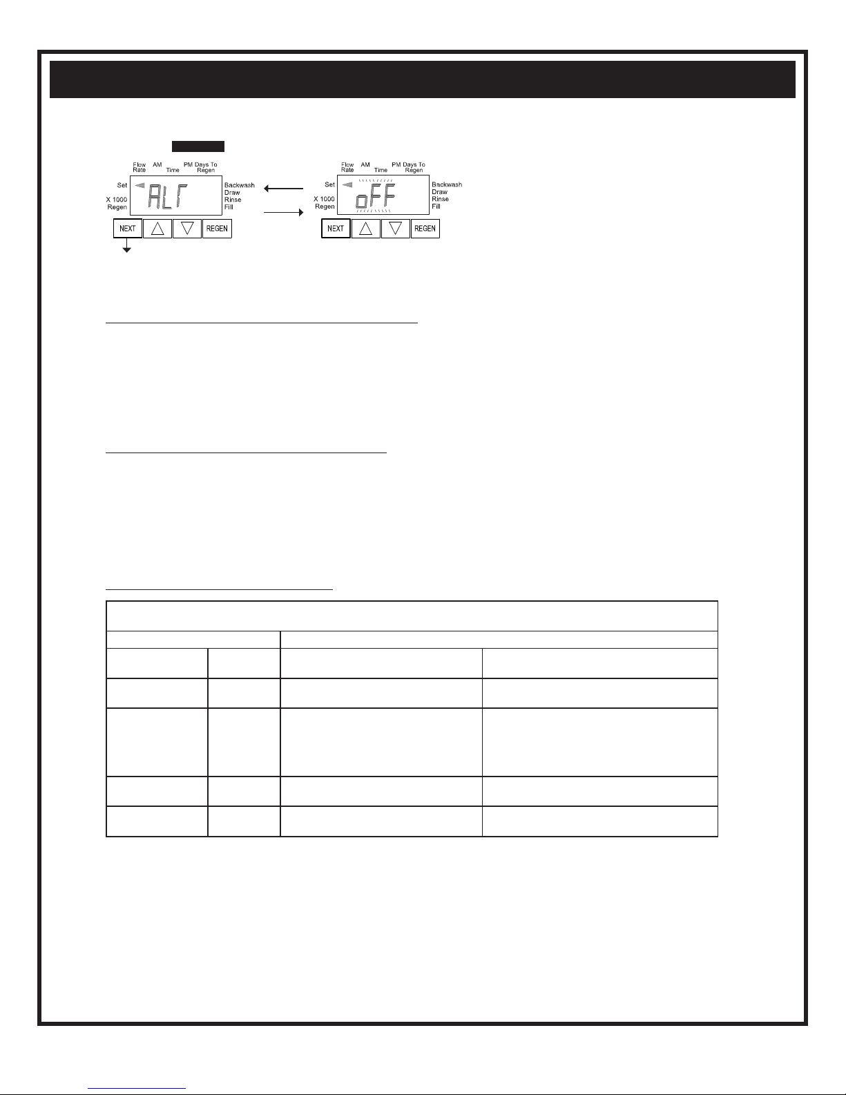
Step 5CS – - Allows selection of one of the following
using the Vor Wbuttons:
• the Control Valve to have no hard water bypass;
• the Control Valve to act as an alternator; or
• the Control Valve to have a separate source during the
regeneration cycle.
Select OFF when none of these features are used.
Only use Clack No Hard Water Bypass Valves or
Clack Motorized Alternating Valves (MAV) with these
selections. Clack No Hard Water Bypass Valves (1” or 1.25” V3070FF or V3070FM) are not designed to be used with the alternator or separate
source functions. The V3063 and V3063BSPT motorized alternating valves are not designed to be used as a no hard water bypass or separate
source inlet if the pressure differential is more than 60 psi.
Conguring the Control Valve for No Hard Water Bypass Operation:
Select nHbP for control operation. For no hard water bypass operation the three wire connector is not used.
Selection requires that a connection to MAV or a Clack No Hard Water Bypass Valve is made to the two pin connector labeled ALTERNATOR
DRIVE located on the printed circuit board. If using a MAV, the A port of the MAV must be plugged and the valve outlet connected to the B
port. When set to nHbP the MAV will be driven closed before the rst regeneration cycle that is not FILL or SOFTENING or FILTERING, and
be driven open after the last regeneration cycle that is not FILL.
NOTE: If the control valve enters into an error state during regeneration mode, the no hard water bypass valve will remain in its current state
until the error is corrected and reset.
Conguring the Control Valve for Separate Source Operation:
Select nHbP for control operation. For separate source operation the three wire connector is not used.
Selection requires that a connection to a Clack Motorized Alternator Valve (MAV) is made to the two pin connector labeled ALTERNATOR
DRIVE located on the printed circuit board. The C port of the MAV must be connected to the valve inlet and the A port connected to the separate
source used during regeneration. The B port must be connected to the feed water supply.
When set to nHbP the MAV will be driven closed before the rst regeneration cycle, and be driven open after the last regeneration cycle.
NOTE: If the control valve enters into an error state during regeneration mode, the MAV will remain in its current state until the error is
corrected and reset.
Selecting the Control Valve to act as an alternator:
Prior to starting the programming steps, connect the interconnect cable to each control valve board’s three pin connector labeled
“INTERCONNECT”. Also connect the meter cord to either control valve to the three pin connector labeled “METER”.
Valve Programming Steps
Conguration
Settings Step 3CS Select Volume Set Volume
Conguration
Settings Step 4CS Set regeneration time option to “On O”. Set regeneration time option to “On O”.
Conguration
Settings Step5CS
Set to ALTA
Connect ALTA valve to the MAV’s A
port and connect the MAV’s two pin wire
connector to the two pin connector labeled
“DRIVE” on the ALTA valve
Set to ALTb
Connect ALTb valve to the MAV’s B port. No
connections between the ALTB valve and the MAV
are made.
Installer Display
Setting Step 2I Enter the Volumetric Capacity for the System Enter the Volumetric Capacity for the System (the
same as Valve A)
Installer Display
Setting Step 3I Set Day Over ride to “oFF” Set Day Over ride to “oFF”
NOTE: If the control valve is in an error state during regeneration mode the MAV will close the B port and keep open the A port until the error is
corrected and reset.
For Clack Corporation alternator systems using the WS1, WS1.25, WS1.5 and WS2L valves the stand by tank will be periodically brought on
line for a short time to keep its bed fresh. The logic is that once a tank is in standby and the time has passed either 6 AM or 6 PM (18:00) at the
next and all subsequent 6 AM and 6 PM times the stand by tank will be brought on line until 10 gallons (37.8 liters) has passed through it. It
will then be placed back on standby.
For Clack Corporation alternator systems using the WS2 valve, when NEXT is pressed after selecting ALTA or ALTb, a display will allow the
user to set the amount of pre-service rinse time for the stand by tank just prior to returning to service.
Press NEXT to go to Step 6CS. Press REGEN to return to previous step.
Step 5CS
Volume Volume
Control Valve cont:

Aqua Treatment Service ©2013 • www.aquat.com 9
Step 7CS
Selecting the use of an outside signal to initiate a regeneration:
Selection only matters if a connection is made to the two pin
connector labeled DP SWITCH located on the printed circuit
board. Following is an explanation of the options:
oFF - Feature not used.
on0 - If the dP switch is closed for an accumulative time of 2
minutes a regeneration will occur immediately.
dELy - If the dP switch is closed for an accumulative time of 2
minutes a regeneration will occur at the scheduled regeneration
time.
HoLd - If the dP switch is closed a regeneration will be prevented
from occurring.
Not viewed if Step 5CS is set to ALTA or ALTb.
Press NEXT to exit Conguration Settings. Press REGEN to
return to previous step.
Step 6CS
Step 6CS – Set duration of the special rinse cycle to be performed prior to a valve returning to Service.
Selectable from 1 - 20 minutes or OFF.
Only viewed if 2.0 is set in 2CS, and ALTA or ALTb is set in 5CS.
Press NEXT to go to Step 7CS. Press REGEN to return to previous step.
Step 7CS
EXIT TO
DISPLAY
SCREENS
Volume
Control Valve cont:

Aqua Treatment Service ©2013 • www.aquat.com
10
Setting Regeneration Cycle Times
Step 1CT - Press NEXT and simultaneously for 5 seconds and release.
If screen in Step 2CT does not appear, the lock on the valve is activated. To
unlock press , NEXT, REGEN, in sequence, then press NEXT and
simultaneously for 5 seconds and release.
Step 3CT - Adjust the length of the backwash from 1-20 minutes using
the or buttons.
Press NEXT to go to Step 4CT. Press REGEN to return to previous step.
Step 4CT - Adjust the length of the regenerant draw from 1-99 minutes
using the or buttons.
Press NEXT to go to Step 5CT. Press REGEN to return to previous step.
Step 5CT - Adjust the length of the second backwash from 1-20 minutes
using the or buttons.
Press NEXT to go to Step 6CT. Press REGEN to return to previous step.
Step 6CT - Adjust the length of rinse from 1-20 minutes using the or
buttons.
Press NEXT to go to Step 7CT. Press REGEN to return to previous step.
Step 7CT - $-+,,"%'!,"( 2%% *(&&#'-,+(*
.%.+*+"#)) *(&," ,(*1/#,"*2%%3(/(',*(%( !)&
%)&%%(,"*(',*(%.%.+*+"#)) *(&," ,(*1/#,"*2%%3(/
control of 0.5 gpm (1.9 lpm).
Press NEXT to exit Regeneration Cycle Times. Press REGEN to return to
previous step.
Step 2CT - Select between SOFTENING or FILTERING.
"'+,,(*#+'(,+,,(( '#++,,(20
second Backwash is automatically added to the regen cycle program after
Rinse 6CT. The status display for this extra backwash will appear as just
another cycle step in sequence.
*++,(!(,(,)*++,(0#,!'*,#('
Cycle Times.
Step 3CT
Step 4CT
Step 5CT
EXIT TO
DISPLAY
SCREENS
Step 7CT
Step 6CT
Step 1CT
Flow
Rate AM Time
Set
Volume
X1000
Regen
Backwash
Brine
Rinse
Fill
PM Days To
Regen
Step 2CT
Control Valve cont:

Aqua Treatment Service ©2013 • www.aquat.com 11
Step 2I - Volumetric capacity in gallons to regeneration.
Press NEXT to go to Step 3I. Press REGEN to exit
Installer Display.
Step 3I - Adjust day override from 1 - 28 or OFF.
Press NEXT to go to Step 4I. Press REGEN to return to
previous step.
Step 4I - Use Vor Wbuttons to set the regen hour.
Press NEXT to go to Step 5I. Press REGEN to return to
the previous step.
Installer Display Settings
Step 1I - To enter Installer Display press the NEXT and
Vbuttons simultaneously for 5 seconds and release.
28 Day or 28/Volume (Gallons) selected in Conguration Settings Step 3CS
Step 1I - To enter Installer Display press the NEXT and
Vbuttons simultaneously for ve seconds and release.
Step 2I - Adjust days from 1 - 28. Press NEXT to go to
Step 3I. Press REGEN to exit Installer Display.
Step 3I - Use Vor Wbuttons to set time of the regen
hour. Press NEXT to go to Step 4I. Press REGEN to return
to previous step.
Step 4I - Use Vand Wbuttons to set the regen minutes.
Press NEXT to exit Installer Display. Press REGEN to
return to previous step.
One of three sets of displays will be shown depending on what was selected in Conguration Settings Step 3CS.
Volume (Gallons) selected in Conguration Settings Step 3CS
Step 5I - Use Vor Wbuttons to set the regen minutes.
Press NEXT to exit Installer Display. Press REGEN to
return to previous step.
Step 2I
Step 3I
Step 1I
Step 4I
Step 5I
EXIT TO
DISPLAY
SCREENS
Step 2I
Step 3I
Step 1I
Step 4I
EXIT TO
DISPLAY
SCREENS
Control Valve cont:

Aqua Treatment Service ©2013 • www.aquat.com
12
Step 3I - Scroll through days 1 to 7 using the NEXT
button. Use the Vor Wbuttons to turn regen on or
off for each individual day (regen indicator on means
regeneration will happen). After completing the 7th day,
press NEXT to go to Step 4I. Press REGEN to go to
previous display.
Step 4I - Use the Vor Wbuttons to set
the regen hour. Press NEXT to go to Step 5I.
Press REGEN to go to previous display.
7 Day or 7/Volume (Gallons) selected in Conguration Settings Step 3CS
Step 1I - To enter Installer Display press the NEXT and
Vbuttons simultaneously for 5 seconds and release.
Step 2I - Use Vor Wbuttons to set the current day of
the week.
Default = 2 (Monday)
1 = SUNDAY
2 = MONDAY
3 = TUESDAY
4 = WEDNESDAY
5 = THURSDAY
6 = FRIDAY
7 = SATURDAY
Press NEXT to go to Step 3I. Press REGEN to exit
Installer Display.
Step 5I - Use the Vor Wbuttons to set the
regen minutes. Press NEXT to exit Installer
Display. Press REGEN to return to previous
display.
Step 2I
Step 3I
Step 1I
Step 4I
Step 5I
EXIT TO
DISPLAY
SCREENS
Control Valve cont:

Aqua Treatment Service ©2013 • www.aquat.com 13
Diagnostics
Step 1D - Press Vand Wbuttons simultaneously for
5 seconds and release. Then press Vand Wbuttons
simultaneously for 2 seconds and release. If screen
in Step 2D does not appear the lock on the valve is
activated. To unlock press W, NEXT, REGEN, Vin
sequence, then press Vand Wbuttons simultaneously
for 5 seconds and release. Then press Vand Wbuttons
simultaneously for 2 seconds and release.
Step 2D - Display shows the number of days since a
regeneration last occurred. Press NEXT to go to Step
3D. Press REGEN to exit Diagnostics.
Step 3D - Display shows the volume of water treated
in gallons treated since the last regeneration. If Volume
(gallons), 28/Volume (gallons), or 7/Volume (gallons)
was selected in Step 3CS and no meter is installed this
display will read 0. Press NEXT to go to Step 4D. Press
REGEN to return to previous step.
Step 4D - Display shows the days in service since start
up. Press NEXT to go to Step 5D. Press REGEN to
return to previous step.
Step 5D - Display shows the total number of
regeneration cycles since start up. Press NEXT to exit
Diagnostics. Press REGEN to return to previous step.
Step 1D
Step 2D
Step 3D
Step 4D
Step 5D
EXIT TO
DISPLAY
SCREENS
Control Valve cont:

Aqua Treatment Service ©2013 • www.aquat.com
14
Parts Breakdown

Aqua Treatment Service ©2013 • www.aquat.com 15
Parts Breakdown cont:

Aqua Treatment Service ©2013 • www.aquat.com
16
6
2
4b
4a
5
1
3
7
8
WS1 Drive Cap Assembly, Downow Piston, Upow Piston, Regenerant Piston and Spacer Stack Assembly
Drawing No. Order No. Description Quantity
1 V3005 WS1 Spacer Stack Assembly 1
2 V3004 Drive Cap ASY 1
3Back Plate Refer to Programming and
Cover Drawing Manual
1
4a V3011* WS1 Piston Downflow ASY 1
4b V3011-01* WS1 Piston Upflow ASY
5 V3174 WS1 Regenerant Piston 1
6 V3135 O-ring 228 1
7 V3180 O-ring 337 1
8 V3105 O-ring 215 (Distributor Tube) 1
Not Shown
V3001 WS1 Body ASY Downflow
1
V3001-02 WS1 Mixing Valve Body ASY
V3001UP WS1 Body ASY Upflow
V3001-02UP WS1 Mixing Valve Body Upflow ASY
*V3011 is labeled with DN and V3011-01 is labeled with UP. Upflow option is not applicable to EE, EI or TC control valves.
Note: The regenerant piston is not used in backwash only applications.
lacPlug
Parts Breakdown cont:

Aqua Treatment Service ©2013 • www.aquat.com 17
Parts Breakdown cont:

Aqua Treatment Service ©2013 • www.aquat.com
18
Rell Flow Control Assembly and Rell Port Plug
Water
Flow
Proper RFC orientation
directs refill water flow
towards the washer face
with rounded edge and text.
Drawing No. Order No. Description Quantity
1 V3195-01 WS1 Rell Port Plug Asy This part is required for backwash only
systems
2 H4615 Elbow Locking Clip 1
3 JCP-P-6 Polytube insert 3/8” 1
4 JCPG-6PBLK Nut 3/8” 1
5 H4613 Elbow Cap 3/8” 1
6 V3163 0-ring 019 1
7 V3165-01* WS1 RFC Retainer Asy (0.5 gpm) 1
8 V3182 WS1 RFC 1
9 V3330-01 WS1 Brine Elbow Asy w/RFC 3/8" 1
Not Shown V3552 WS1 Brine Elbow Asy w/RFC 1/2" Option
Not Shown H4650 Elbow ½” with nut and insert Option
*Assembly includes V3182 WS1 (0.5 gpm) RFC.
9
Parts Breakdown cont:
This manual suits for next models
1
Table of contents
Other ATS Water Filtration System manuals