ATV IPEMB2FI User manual

Please read this manual thoroughly before use, and keep it handy for future reference.
Full HD IR
Network Camera
INSTRUCTION MANUAL

1
WARNING
TO REDUCE THE RISK OF FIRE OR ELECTRIC SHOCK, DO NOT EXPOSE THIS
PROCUCT TO RAIN OR MOISTURE. DO NOT INSERT ANY METALLIC OBJECT
THROUGH THE VENTILATION GRILLS OR OTHER OPENNINGS ON THE
EQUIPMENT.
Apparatus shall not be exposed to dripping or splashing and that no objects filled with
liquids, such as vases, shall be placed on the apparatus.
CAUTION
EXPLANATION OF GRAPHICAL SYMBOLS
The lightning flash with arrowhead symbol, within an equilateral triangle, is
intended to alert the user to the presence of uninsulated "dangerous
voltage" within the product’s enclosure that may be of sufficient magnitude
to constitute a risk of electric shock.
The exclamation point within an equilateral triangle is intended to alert the
user to the presence of important operating and maintenance (servicing)
instructions in the literature accompanying the appliance.

2
1.1.1.1FCC COMPLIANCE STATEMENT
INFORMATION TO THE USER:THIS EQUIPMENT HAS BEEN TESTED AND FOUND TO
COMPLY WITH THE LIMITS FOR A CLASS A DIGITAL DEVICE, PURSUANT TO PART 15 OF THE FCC
RULES. THESE LIMITS ARE DESIGNED TO PROVIDE REASONABLE PROTECTION AGAINST HARMFUL
INTERFERENCE WHEN THE EQUIPMENT IS OPERATED IN A COMMERCIAL ENVIRONMENT. THIS
EQUIPMENT GENERATES, USES, AND CAN RADIATE RADIO FREQUENCY ENERGY AND IF NOT
INSTALLED AND USED IN ACCORDANCE WITH THE INSTRUCTION MANUAL, MAY CAUSE HARMFUL
INTERFERENCE TO RADIO COMMUNICATIONS.
CAUTION:CHANGES OR MODIFICATIONS NOT EXPRESSLY APPROVED BY THE PARTY
RESPONSIBLE FOR COMPLIANCE COULD VOID THE USER'S AUTHORITY TO OPERATE THE
EQUIPMENT.
THIS CLASS ADIGITALAPPARATUS COMPLIES WITH CANADIAN ICES-003.
CET APPAREIL NUMÉRIQUE DE LA CLASSE A EST CONFORME À LA NORME NMB-003 DU CANADA.
1.1.1.2 CE COMPLIANCE STATEMENT
WARNING: This is a Class A product. In a domestic environment this product may cause
radio interference in which case the user may be required to take adequate measures.
CAUTION
RISK OF EXPLOSION IF BATTERY IS REPLACED BY AN INCORRECT TYPE.
DISPOSE OF USED BATTERIES ACCORDING TO THE INSTRUCTIONS

3
IMPORTANT SAFETY INSTRUCTIONS
1. Read these instructions.
2. Keep these instructions.
3. Heed all warnings.
4. Follow all instructions.
5. Do not use this apparatus near water.
6. Clean only with dry cloth.
7. Do not block any ventilation openings. Install in accordance with the manufacturer’s
instructions.
8. Do not install near any heat sources such as radiators, heat registers, stoves, or ot
her apparatus (including amplifiers) that produce heat.
9. Do not defeat the safety purpose of the polarized or grounding-type plug. A polariz
ed plug has two blades with one wider than the other. A grounding type plug has t
wo blades and a third grounding prong. The wide blade or the third prong are pro
vided for your safety. If the provided plug does not fit into your outlet, consult an e
lectrician for replacement of the obsolete outlet.
10. Protect the power cord from being walked on or pinched particularly at plugs, conv
enience receptacles, and the point where they exit from the apparatus.
11. Only use attachments/accessories specified by the manufacturer.
12. Use only with the cart, stand, tripod, bracket, or table specified
by the manufacturer, or sold with the apparatus. When a cart i
s used, use caution when moving the cart/apparatus combinatio
n to avoid injury from tip-over.
13. Unplug this apparatus during lightning storms or when unused f
or long periods of time.
14. Refer all servicing to qualified service personnel. Servicing is re
quired when the apparatus has been damaged in any way, suc
h as power-supply cord or plug is damaged, liquid has been sp
illed or objects have fallen into the apparatus, the apparatus has been exposed to
rain or moisture, does not operate normally, or has been dropped.
15. CAUTION –THESE SERVICING INSTRUCTIONS ARE FOR USE BY QUALIFI
ED SERVICE PERSONNEL ONLY. TO REDUCE THE RISK OF ELECTRIC SH
OCK DO NOT PERFORM ANY SERVICING OTHER THAN THAT CONTAINED
IN THE OPERATING INSTRUCTIONS UNLESS YOU QRE QUALIFIED TO D
O SO.
16. Use satisfy clause 2.5 of IEC60950-1/UL60950-1 or Certified/Listed Class 2
power source only.
17. ITE is to be connected only to PoE networks without routing to the outside plant.

4
Contents
1. Description............................................................................................................ 1
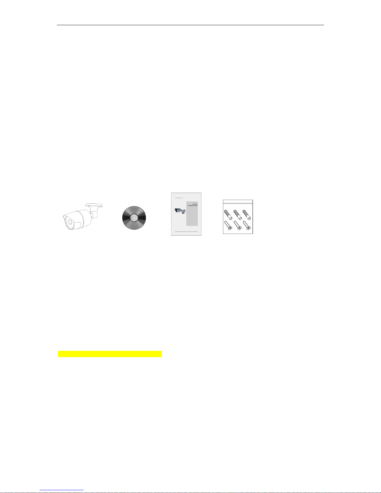
1.1 Components................................................................................1
1.2 Key Features ...............................................................................1
2. System Connection.............................................................................................. 2
2.1 Connection..................................................................................2
2.2 Network Connection and IP assignment...................................5
3. Operation............................................................................................................... 6
3.1 Download and Install ActiveX ....................................................6
3.2 User Login...................................................................................7
3.3 Live Video....................................................................................7
3.3.1 Video Control ...........................................................................8
3.4 Configure.....................................................................................9
3.4.1 Quick Setup..............................................................................9
3.4.2 Image......................................................................................12
3.4.2.1 ISP Configure ......................................................................12
3.4.2.2 Privacy Regional.................................................................13
3.4.2.3 OSD......................................................................................13
3.4.2.4 Day/Night Configure ...........................................................14
3.5.1 Network...................................................................................16
3.5.1.1 Network Configure..............................................................16
3.5.1.2 PPPoE Configure ................................................................17
3.5.1.3 DDNS Configure..................................................................17
3.5.1.4 E-mail Configure .................................................................18
3.5.1.5 FTP Configure .....................................................................19
3.5.1.6 Port Mapping.......................................................................19
3.5.2 Alarm.......................................................................................20
3.5.2.1 Motion Detection.................................................................20
3.5.2.2 I/O.........................................................................................21
3.5.3 Audio & Video.........................................................................22
3.5.3.1 Stream Configure................................................................22
3.5.3.2 ROI Setting ..........................................................................23
3.5.4 Storage ...................................................................................23
3.5.4.1 Record Configure................................................................23
3.5.4.2 Capture Configure...............................................................24
3.5.5 Security...................................................................................25

5
3.5.5.1 User Management...............................................................25
3.5.5.2 IEEE 802.1xs........................................................................25
3.5.5.3 HTTPS Configure ................................................................26
3.5.5.4 RTSP Authentication...........................................................26
3.5.5 System....................................................................................27
3.5.5.1 Time Parameters.................................................................27
3.5.5.2 Device Information..............................................................28
3.5.5.3 Maintenance........................................................................28
3.5.5.4 Upgrade Device...................................................................29
3.5.5.5 Connection..........................................................................30
3.5.6 Local Configure......................................................................30
3.6 Log.............................................................................................31
3.7 Logout .......................................................................................31

1
1. Description
The Network Camera supports the network service for an image sensor with progressive scan, which
can be monitored on a real-time screen regardless of distances and locations. By using its dedicated
program, many users are able to have an access to the Network Camera at once or a single user can
monitor various network cameras at the same time. It also enables users to store, retrieve and play an
image by using a PC. All the settings and real-time monitoring screens are also provided through an
access to the web.
The Network Camera is fully featured for security surveillance and remote monitoring needs. It is based
on the DSP compression chip, and makes it available on the network as real-time, full frame rate
Motion JPEG and H.264 (or MPEG-4) video streams.
1.1 Components
The system comes with the following components:
IR Bullet Camera Installation CD Installation Guide Accessory Kit
or Turret camera
Notes:
1. Check your package to make sure that you received the complete system, including all
components shown above.
2. Adapter for DC 12V is not supplied.
1.2 Key Features
Simultaneous H.264, M-JPEG video encoding compression and streaming
Support ISP 2ATechnology with (AWB, AE)
Support DWDR, 3D-DNR, Digital Zoom
Support 1280*720@30FPS, 1280*960@30FPS, 1920*1080@30FPS resolution real-time encoding
Support CGI/SDK Development, ONVIF V2.4
IE BROWSER/SAFARI/GOOGLE CHROME/FIREFOX/OPERA, Smart manager, Tive Mobile (Android,
iPhone and iPad)
Support multi-viewer to access concurrently
Support dual-encoding streams: Main stream, sub stream
Support privacy protection mode, motion detection and sensor alarm functions
Auto-retrieve function and auto-connection network
Network Protocol: TCP/IP, UDP, HTTP, 802.1x, DHCP, DNS, DDNS, RTP, RTSP, PPPoE, SMTP, NTP, SNMP,
FTP, UPNP

2
Multi-language: Chinese, English, Japanese, Portuguese, Russian, Spanish
2. System Connection
2.1 Connection
Connection Cable
NO
Name
Description
1
Power Cable
Cable for Power source (DC 12V)
2
Ethernet Cable
Cable for Ethernet (POE)
NO
Name
Description
1
Lens
Allows wide area to be monitored
2
Power Cable
Cable for Power source (DC 12V)
3
Ethernet Cable
Cable for Ethernet (POE)

3
Camera Dimension
Dimensions Unit: mm
Base Installation
Secure the camera to the wall or ceiling by the camera stand (individual purchase).
Ceiling Mount Wall Mount

4
Carefully remove the contents from the box, and verity that nothing was damaged in shipment.
1) Mark the screw hole positions on the ceiling or wall surface using the Template Sheet.
2) Disassemble the camera by removing the dome cover.
3) Mount the camera assembly using the Anchors (x2) and Screws (x2) to the surface of the
ceiling or wall.
Connecting to the RJ-45
Connect a standard RJ-45 cable to the network port of the network camera. Generally a cross-over
cable is used for directly connection to PC, while a direct cable is used for connection to a hub or
switch.
Connecting the Power
Connect the DC 12V power adaptor to the camera. (This connection is not used if using PoE power)

5
2.2 Network Connection and IP assignment
The Network Camera supports the operation through the network. When a camera is first connected to
the network it has no assigned IP address. So, it is necessary to allocate an IP address to the device
with the “Smart Manager” utility found in the supplied CD. (Default IP 192.168.30.220)
1. Connect the Network Camera / device to the network and power up.
2. Start SmartManager utility (Start > All programs > SmartManager > SmartManager), the main
window will be displayed, after a short while any network devices connected to the network will be
displayed in the list.
3. Select the camera on the list and click right button of the mouse. You can see the pop-up menu
below.
4. Select Assign IP. You will see the "Assign IP Address" window. Enter the required IP address.
Note: For more information, refer to the Smart Manger User’s Manual.

6
3. Operation
The Network Camera can be used with Windows operating system and browsers. The recommended
browsers are Internet Explorer, Safari, Firefox, Opera and Google Chrome with Windows.
Note:To view streaming video in Microsoft Internet Explorer, set your browser to allow ActiveX
controls.
3.1 Download and Install ActiveX
You need to install ActiveX Control when you access IP Camera for the first time through IE browser.
Installation Method:
1) Input the IP address of IP Camera in the browser's address bar (for example: 192.168.1.10) to enter into login
page.
2) Click [Download ActiveX]
3) Pop up a file download dialog box, click [Run] or [Save] to download ActiveX.
4) After the download is complete, double-click the downloaded file “WebClient”, select the installation path, and
click [Install] to install “WebClient”.
5) After the installation is complete, click [Finish] to exit.

7
3.2 User Login
Reopen IE web browser after the ActiveX installation completes, input the IP address of IP Camera (192.168.1.10
by default) to enter into login page. Select the system language, input user name and password, then click [Login]
button to enter the main interface.
Note: The default user name is “admin”, the default password is blank.
3.3 Live Video
After signing in you will see the live video page, or click [Live Video] button in the menu bar to enter this page.
User can do many operations like play, stop, talkback, monitor audio, record, capture, zoom in, show alarm, view
in full-screen mode, control PTZ, adjust video parameters, select stream type and adjust display scale.

8
3.3.1 Video Control
[Main / Sub Stream]: Select the stream according to the network environment: main stream is HD channel and
sub stream is SD channel.
[16:9 / 4:3]: Adjust the display scale.
[Play]: Click button to open the current video.
[Stop]: Click button to close the current video.
[Talkback]: Audio talkback switch. Click button to perform the talkback between PC and IP Camera; the
state is changed to after enable audio talkback, click this button to stop talkback.
[Audio]: Open or close the sound of live video.
[Record]: Manual recording switch. Click button to record current video, and save them in AVI format to
“Local recording files path” of local config; the state is changed to after enable recording, click this button to
stop recording.
[Capture]: Click button to generate the screenshot of current views, and save it in JPG format to “Local
capture files path” of local config.
[Digital Zoom]: Click button to enter the E-Zoom mode. The image will be magnified. User can click and
hold your left mouse button to move the image, click to exit the E-Zoom mode.
[Show Alarm]: Click button to pop up alarm information list, it shows the alarm IP, alarm time and alarm
description. Click close button or button to close it.
[Full Screen]: Double-click the video screen to display video in full-screen mode, double-click again or press Esc
key to exit full screen mode.
[Video Parameters]: Click to open PTZ control panel, and adjust the brightness, hue, contrast, saturation
and sharpness of video, click [Default] button to restore the default values.
Note: Note: Support 5 users online at the same time.

9
3.4 Configure
Click [Configure] button in the menu bar to configure parameters.
3.4.1 Quick Setup
Step 1: Time Parameters
1) Set up the IP Camera’s date, time and current time zone, or click [Sync PC time] to sync system time with PC.
Enable NTP Service and set its IP and port number, IP Camera will sync system time with NTP server.
2) If you want to use DST function, enable it and set start & end time and shift time.
3) Click [Next] to proceed.
Step 2: Stream Configure

10
1) Set up appropriate stream parameters.
Parameter
Description
Stream ID
Main stream: HD channel. Sub stream: SD channel.
Stream type
Include Only Video and Video & Audio.
Encode type
Support the standard H.264 and M-JPEG video encoding.
Frame rate
Set the encoding frame numbers per second.
Frame interval
The smaller frame interval, the higher image bitrate and the better
image quality you get.
Resolution
Set the resolution of video.
Video format
Set PAL or NTSC.
Bit type
CBR: constant encoding bitrate. VBR: variable encoding bitrate.
Stream Size
Different stream ID has different bitrate.
2) Click [Back] to change previous settings. Click [Next] to proceed.
Step 3: User Management
1) Add a user: Enter the new user's name and password, set the appropriate user right, and then click [Add].
2) Modify a user: Select a user in the list, modify user information or right, and then click [Modify].
3) Delete a user: Select a user in the list, and then click [Delete].
4) Click [Back] to change previous settings. Click [Next] to proceed.

11
Step 4: Network Parameters
1) Set up the IP Camera’s port number.
2) Set up its IP address, net mask and gateway. Please avoid conflict with the IP addresses of other devices or
PC. If DHCP function of router and IP Camera is enabled, it will automatically obtain IP address from the
router.
3) If you want to use multicast function, set its IP address and port number.
4) Set up the DNS server as your local DNS address for using DDNS function.
5) Click [Back] to change previous settings. Click [Completed] to save the settings.
Note: After modify and save network parameters, IP Camera will restart. All ports (including device port, media port,
web port, ONVIF port, etc) must be forwarded when IPC is accessed via internet.

12
3.4.2 Image
3.4.2.1 ISP Configure
[Brightness / Contrast / Hue / Saturation / Sharpness]: Drag the slider to adjust the brightness, contrast, hue,
saturation and sharpness of video, range from 1 to 255.
[DWDR]: Open this function to balance the contrast between light and dark areas within an image. User can see
highlight areas (under strong light) and low-light areas (shadows, backlighting, etc) simultaneously, otherwise
highlight areas display white and dark areas display black.
[Video Standard]: In indoor environment, if the flashing lamps result in image scintillation, please select 50HZ or
60HZ according to the power frequency.
[Mirror Mode]: Enable or disable mirroring function, set the mirror / flip / mirror and flip mode, video will rotate
horizontally / vertically / both horizontally and vertically.
[AWB Mode]: Select the appropriate mode to adjust the color of screen and make the picture closer to actual
results. There are six modes to choose from.
[3D Noise]: Open or close 3D DNR function.
[Noise Level]: Drag the slider to set the processing level of reducing noise, range from 1 to 255.
[Exposure]: Auto exposure will adjust exposure automatically according to the intensity of light. Manual exposure
can adjust exposure rating manually.
[Indoor And Outdoor]: Select indoor or outdoor mode to get the suitable display result.
Click OK button to save the setting. Click Default button to restore the default setting. When the setting is not saved,
click Refresh button to return to the previously saved parameters; when the setting has been saved, click Refresh
button to query whether the setting is successful.

13
3.4.2.2 Privacy Regional
[Enable]: Enable or disable privacy function.
[Color]: Select the color overlay of privacy area.
Enable privacy function, click and drag cursor to set the privacy area of video image. An image can be entirely or
partially masked, it supports 4 areas at maximum.
Click Clear all button to clear all privacy areas. Click Clear Selected Area button to clear selected privacy area.
Click OK button to save the setting. When the setting is not saved, click Refresh button to return to the previously
saved parameters; when the setting has been saved, click Refresh button to query whether the setting is
successful.
3.4.2.3 OSD

14
Time
[Enable]: Enable this function to display system time.
[Color]: Select different colors for time display. The background color of time area which has a transparency of 30%
will automatically adjust according to the character color.
Text
[Enable]: Enable this function to display text content.
[Color]: Select different colors for text display. The background color of text area which has a transparency of 30%
will automatically adjust according to the character color.
[Text]: Click text box to self-define the channel name, it supports 40 English characters or 20 Chinese words at
maximum.
Click and drag system time or text content to adjust the display position.
Click OK button to save the setting. When the setting is not saved, click Refresh button to return to the previously
saved parameters; when the setting has been saved, click Refresh button to query whether the setting is
successful.
3.4.2.4 Day/Night Configure
This manual suits for next models
1
Table of contents
Other ATV Security Camera manuals
Popular Security Camera manuals by other brands

Alpha Networks
Alpha Networks PT-3152 Quick installation guide

Eneo
Eneo IPP-72A0023MIA user manual

Uniden
Uniden App Cam Spotlight+ quick start guide

ZyXEL Communications
ZyXEL Communications IPC-4605N quick start guide

Assa Abloy
Assa Abloy Yale SV-DAFX-B manual

Vertiv
Vertiv ES-HND200I-EI Installer/user guide