manuals.online logo
Brands
  1. Home
  2. •
  3. Brands
  4. •
  5. Fairford
  6. •
  7. Controllers
  8. •
  9. Fairford HFE-30 User guide

Fairford HFE-30 User guide

page 1 M-2025-F 081007
HFE-30 30 Amp @ 110-230 Volts
APPLICATION
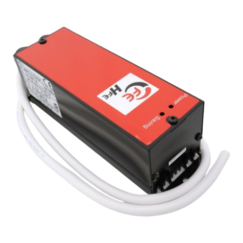
HFE Energy Saving soft starters are designed to
control single phase AC motors. Operation is fully
automatic, a low starting voltage is applied to the
motor as soon as the supply is switched on. The
internal automatic ramp control immediately takes
over and raises the voltage progressively, causing
the motor to accelerate smoothly.
At the end of the ramp period, the motor is operated
in Energy Saving mode and the HFE continuously
regulates the voltage to match mechanical load.
Energy consumption at light loads is reduced, motor
winding and case temperatures are lowered, motor
life is extended, noise levels are reduced and power
factor is improved.
The LED in the unit indicates when the unit is
ENERGY SAVING. As energy consumption is
reduced the ENERGY SAVING LED flashes at a
slower rate.
The HFE remains in circuit until the supply is discon-
nected. The HFE automatically resets and is ready for
the next start.
Digital Soft Starters
Soft Starters and Energy
Optimising Soft Starters
FAIRFORD
ELECTRONICS
Hfe
Safety at Work
ISOLATE FROM THE SUPPLY BEFORE WORKING ON THE UNIT OR MOTOR
It is the responsibility of the installer and user to ensure that this equipment is installed,
operated and maintained in accordance with the Health and Safety at Work Act in the
United Kingdom and all applicable legislation, regulations and codes of practice relevant to
your location.
Only qualified personnel should install this equipment, after first reading and understanding
this document. The installation instructions must be followed, and any questions or doubt
must be referred to the supplier of the equipment.
The system may be configured to allow for auto restart controlled from contacts on the
motor side of the unit. Users and operators must always take all necessary precautions to
prevent damage to equipment and especially to prevent the risk of injury to personnel
working on or near the motor and driven equipment.
The manufacturer does not assume any liability, express or implied, for any consequences
resulting from inappropriate, negligent or incorrect installation, application, use or adjust-
ment of the product or circuit design, or from mismatching of a soft starter to a motor.
page 2 M-2025-F 081007
“fridge mode
link, J4”
LED
indicator
Ramp time
Optimise
link, J1
25
40.2 40.2
59.2
97.5
Three off Ø21mm
holes for
cable glands
195
215
228
ML MN N L
- Supply Live
- Supply Neutral
- Motor Neutral
- Motor Live
MM
LN
NL
Earth/Ground
M5 Screw
M M N, L
L, N,
1
mm
2
AWG mm Nm lbs-inch mm
1.5-25 12 - 4 13 2 18 0.8 x 4
MOUNTING
The module must be fixed to a
vertical surface. To ensure
free air movement a minimum
clearance of 40mm must be
maintained above and below
the unit.
Mechanical Details HFE-30
page 3 M-2025-F 081007
110/230V~
Live
Motor Live
Motor Neutral
Supply Live
Supply Neutral
Earth/Ground
Earth/Ground
Neutral
Earth/Ground
Main
winding
Auxiliary
winding
Motor connected for
Capacitor Start - Run Run
Cap
Start
Cap
Connect Start Capacitor
to Supply live for
High Torque or Heavy starting
Centrifugal or voltage
switch controls
start Capacitor
NL MM
NL
WIRING
The soft starter is normally inserted into the circuit between the motor and whatever switchgear
is normally used for isolation or switching. The unit can also be fitted before switchgear so that
it can be installed in the supply to equipment which has it’s own mechanical control.
This feature allows for easy installation on equipment such as refrigeration where the need to
disturb internal wiring is avoided.
Operation
Set the ramp time potentiometer to midway to approx 2 seconds and start the system. If the
motor turns instantly when the soft starter is energised and accelerates satisfactorily then no
further adjustment is required. If the rate of acceleration is too great stop the unit and turn the
ramp time potentiometer clockwise then restart. Adjust anti–clockwise for a shorter ramp time
setting to increase the rate of acceleration. The motor should turn instantly when the soft
starter is energised. If not, rearrange the connection of the starting capacitor as shown in fig 1
The terminations are made with industry standard cage clamp screw terminals directly onto the
circuit board on all units.
The incoming power supply is connected to the terminals marked ‘L’ and ‘N’. For EMC compli-
ance it is important that the line circuit is connected to L and the neutral circuit to N. Outgoing
connections from the HFE are taken from the terminals marked ‘LM’ and ‘NM’ to the motor or
load input terminals (see diagram). Ensure that a good connection is made to the earth termi-
nals provided.
Fuses or other type of short-circuit protection are required for protection against a cable or
motor terminal box fault. These must be fitted externally and on the supply side of the unit. See
“Specifications” section for recommended fuse type and cut-out device.
Typical connection
for the HFE.
Extra starting torque
may be needed for
loads which have a
particularly ‘sticky’
starting characteristic.
This can be achieved by
rearranging the internal
connection of the
starting capacitor,
bringing the connection
out and to the supply
side of the starter as
shown.
Document No. FD202504-F page 4 M-2025-F 081007 ©
Fairford Electronics Limited, Coombe Works, Derby Road, Kingsbridge, Devon TQ7 1JL, UK
TEL: + 44 (0) 1548 857494 FAX: + 44 (0) 1548 853118
EMAIL: [email protected] WEB: www.fairford.co.uk
SPECIFICATIONS
Pedestal Voltage Fixed at ~15%.
Start Time: Continuously variable from ½S -5S.
Terminations: Cage clamp terminals suitable for 1.5mm2(12awg)
to 25mm2 (4awg)
Ambient Temperature: 0°C to 40°C without derating.
Enclosure: IP30 with standard cover:
Rated Operational Voltage: Ue: 110 to 230V ac (–15% +10%), 50/60Hz
Recommended cut–out device: 32A rated MCB, Trip Characteristic “C“, Form 1.
Rated insulation voltage: Ui: 300V.
Rated impulse withstand voltage: Uimp: 4kV (1.2/50µs).
Short circuit co–ordination: Type 1 , Iq: 5kA when protected by recommended Fuse
Fuse Type: Bussmann 170M3113 or Ferraz 6,6 URD 30 D08A 0125.
Design standards: IEC 60947–4–2: “AC Semiconductor Motor Controllers and Starters”.
STARTING
Rating Table
30A : AC–53a : 3–3:99–60
The rated
operational
current
Continuous
connection
Allowed start
current (X Ie)
Allowed start
time (S)
time on
load (%)
Equally spaced
starts/Hr
HFE-30
Current
(Amps) Time
(Secs)
30 AC53a 90 3 99% 60
Model Utilisation
Category Up to
Starts/Hr
DutyStartLoad
Amps (Ie)

Other Fairford Controllers manuals

Fairford Synergy SGY-101 User manual

Fairford

Fairford Synergy SGY-101 User manual

Fairford Synergy SGY-101 User manual

Fairford

Fairford Synergy SGY-101 User manual

Fairford Synergy SGY-401 User manual

Fairford

Fairford Synergy SGY-401 User manual

Fairford XFE Series Owner's manual

Fairford

Fairford XFE Series Owner's manual

Fairford Dfe series User manual

Fairford

Fairford Dfe series User manual

Fairford iERS HFE-1 User manual

Fairford

Fairford iERS HFE-1 User manual

Fairford synergy User manual

Fairford

Fairford synergy User manual

Fairford HFE-2 User manual

Fairford

Fairford HFE-2 User manual

Fairford agility Series User manual

Fairford

Fairford agility Series User manual

Fairford SDF-02 User manual

Fairford

Fairford SDF-02 User manual

Fairford Dfe series User manual

Fairford

Fairford Dfe series User manual

Fairford agility Series User manual

Fairford

Fairford agility Series User manual

Popular Controllers manuals by other brands

WEG SSW-08 user manual

WEG

WEG SSW-08 user manual

NXP Semiconductors PXN2020 Reference manual

NXP Semiconductors

NXP Semiconductors PXN2020 Reference manual

Masibus LC5296 user manual

Masibus

Masibus LC5296 user manual

Sanken SWL Series Operation manual

Sanken

Sanken SWL Series Operation manual

Yamaha MCX-10 owner's manual

Yamaha

Yamaha MCX-10 owner's manual

PowerTech MP3745 user manual

PowerTech

PowerTech MP3745 user manual

Atlas Systems ECHC-08-04 Operation manual

Atlas Systems

Atlas Systems ECHC-08-04 Operation manual

Omron CPM1A Brochure & specs

Omron

Omron CPM1A Brochure & specs

Lütze DIOLINE PLC operating instructions

Lütze

Lütze DIOLINE PLC operating instructions

KEYKING TA7003NT user manual

KEYKING

KEYKING TA7003NT user manual

Mi Casa Verde VERALITE quick start guide

Mi Casa Verde

Mi Casa Verde VERALITE quick start guide

Conductix-Wampfler CQF 04/2 + Interface M12 operating instructions

Conductix-Wampfler

Conductix-Wampfler CQF 04/2 + Interface M12 operating instructions

resideo VR4205 quick start guide

resideo

resideo VR4205 quick start guide

Cololight Colo Play user manual

Cololight

Cololight Colo Play user manual

ITT Bell & Gossett ZoneTrol II Z-2 Installation, operation and service instructions

ITT

ITT Bell & Gossett ZoneTrol II Z-2 Installation, operation and service instructions

Aimco UEC-4800EPL instruction manual

Aimco

Aimco UEC-4800EPL instruction manual

Siemens 25 Replacement Parts and Instruction Guide

Siemens

Siemens 25 Replacement Parts and Instruction Guide

Belimo AFB Series manual

Belimo

Belimo AFB Series manual

manuals.online logo
manuals.online logoBrands
  • About & Mission
  • Contact us
  • Privacy Policy
  • Terms and Conditions

Copyright 2025 Manuals.Online. All Rights Reserved.