Entes MPR-45 User manual

1
INDEX
SAFETY AND WARNINGS.............................................................................................3
Warning.......................................................................................................................3
Safety ..........................................................................................................................3
Warranty......................................................................................................................3
OPERATING CONDITIONS............................................................................................4
INTRODUCTION.............................................................................................................5
General Features.........................................................................................................5
Applications.................................................................................................................6
MPR-4 Series Products...............................................................................................6
Overview......................................................................................................................6
Terminals.................................................................................................................7
Front Panel ..............................................................................................................7
Button Functions..........................................................................................................8
Terminal Structure.......................................................................................................9
INSTALLATION.............................................................................................................10
3P4W (3 Phase with Neutral) Connection .................................................................10
3P3W (3 Phase without Neutral) Connection ............................................................10
Aron without Neutral Connection...............................................................................11
3P4W BLN (3 Phase Balanced with Neutral) Connection..........................................11
3P3W BLN (3 Phase Balanced without Neutral) Connection.....................................12
CONNECTION TEST ................................................................................................13
Line Termination Resistor..........................................................................................13
OPERATING INSTRUCTIONS.....................................................................................14
Measurement Screens...............................................................................................14
Current, Voltage and Frequency Screens..............................................................14
Power and Power Factor Screens..........................................................................16
Energy and Time Screens......................................................................................18
THD and Harmonics Screens.................................................................................21
Minimum, Maximum and Demand Screens ...........................................................22
Setup Screen.............................................................................................................28
Device Installation Settings....................................................................................28
Display Settings .....................................................................................................32
Time Settings.........................................................................................................33
RS-485 Communication Settings...........................................................................35
Input Parameter Settings .......................................................................................36
Output Parameter Settings.....................................................................................38
Recording Settings.................................................................................................39
Pulse Input Settings...............................................................................................42
Pulse Output Settings ............................................................................................43
Operating Hours Settings.......................................................................................45
Alarm Settings........................................................................................................46
Tariff Settings.........................................................................................................50
Reset Settings........................................................................................................51
System Settings.....................................................................................................54
MPR-4 SERIES NETWORK ANALYSER
USER MANUAL

2
Analog Output Settings..........................................................................................57
Reporting Screen.......................................................................................................60
TECHNICAL FEATURES AND APPENDIX..................................................................62
Technical Features....................................................................................................62
Measurement Menu Map 1........................................................................................64
Measurement Menu Map 2........................................................................................65

3
SAFETY AND WARNINGS
Warning
Failure to follow the instructions below may result in serious injury or death.
Cut all power before connecting the device.
Once the device is energized, do not remove the front panel.
Do not attempt to clean the device with a solvent or another similar agent. Use only a dry piece of
cloth.
Check the correct connections before energizing the device.
Contact your authorized seller in case of any problems with your device.
Device is only for panel mounting.
F Type fuse must be used and its current limit must be 1 A.
The manufacturing company is not responsible for the consequences resulting from failure to comply with
these precautions.
Safety
Read the entire user manual before using the device.
A switch or circuit breaker must be connected between the network and the auxiliary supply of
the device.
Connected switch or circuit breaker must be in close proximity to the device.
Connected switch or circuit breaker must be marked as the disconnecting device for the
equipment.
Warranty
Device has a 2 (two) year warranty. Any repairs on the device must be done only by the manufacturer.
Otherwise, the device warranty will be void.

4
OPERATING CONDITIONS
Operating Conditions
Range
Supply Voltage
45 ~ 265 VAC
Supply Frequency
45 ~ 65 Hz.
Maximum Measuring Current
5,5 A
Maximum Measuring Voltage
690 VAC (VLL)
Operating Temperature
-5 ~ +55 ºC
Storing Temperature
-25 ~ +70 ºC
Maximum Ambient Humidity
90%
Communication Speed
2400 ~ 115200 bps

5
INTRODUCTION
General Features
oWide supply range
oCustom FSTN display with backlight
o4 voltage measuring inputs
o4 current measuring inputs
o4 language options
o16MB internal memory
oReal time clock
oAlarm
oHour counters (Operating hour and total hour)
oCommunication via RS-485
oModule input:
oDigital Input / Output
2 Digital Inputs
2 Digital Outputs
2 Digital Inputs + 2 Digital Outputs
Relay Output
2 relay outputs: 5A/250VAC; NO
Analog Output
2x 0/4 –20mA outputs or
2x 0/2 –10V outputs
Temperature Input
4x PTD or 2x thermo-couple inputs. Optionally 1 digital input + 1 digital output.
oMeasured parameters: Current, Voltage, Power, Energy, THDI and THDV, Power factor
and cosφ
o96 x 96 panel mount
oEvent records storage and management
oUser password
oChanging primary and secondary values of current and voltage transformers
oMaking measurements on 3 Phase with Neutral, 3 Phase without Neutral, Aron
connected systems
oContrast setting
oDemand time setting
oDaylight savings time switching
oTariff settings
6
Applications
MPR-4 Series devices are microprocessor-based devices which are designed to measure all parameters
of an electrical network, calculate the consumption values and display these on its LCD screen.
Measured parameters will be recorded in real-time thanks to internal flash memory and Real Time Clock
chip. These recorded values then can be accessed and monitored remotely via RS-485 line with Modbus
RTU protocol. Ethernet feature can be used instead of RS-485.
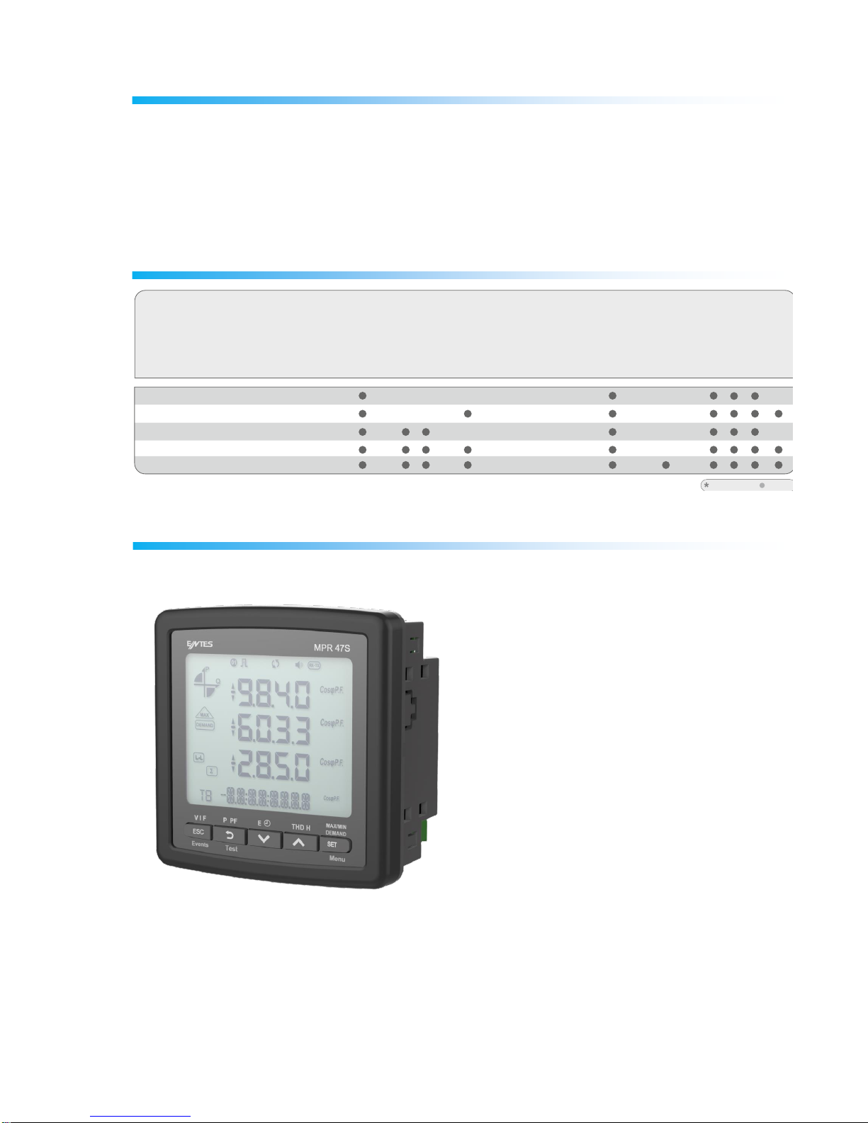
MPR-4 Series Products
Modular structure Standard
RS-485
Operating Hours
Meter
Alarm
Event Logs
Profile Records
Temperature
Analog Output(mA/V)
Relay Output
Memory
16MB
16MB
96x96
96x96
96x96
96x96
*
*
*
*
*
*
*
*
*
*
*
*
*
*
*
*
*
*
*
*
*
*
*
*
Pulse Counter
*
*
MPR-45
MPR-45S
MPR-46
MPR-46S
MPR-47S 96x96
Individual Harmonics
* * * * * * 16MB *
Voltage/Current
Unbalances
Dimensions / mm
3xV, 3xI,Frequency,W,
VAr,VA, P, Q, S,
kWh,kVArh,kVAh
Demand, Max.,Min.
Cos I neutral,
THD-I %
THD-V %
Digital Input
Digital Output
Pulse Output
Real Time Clock
Product Code
PRODUCT SELECTION TABLE
51
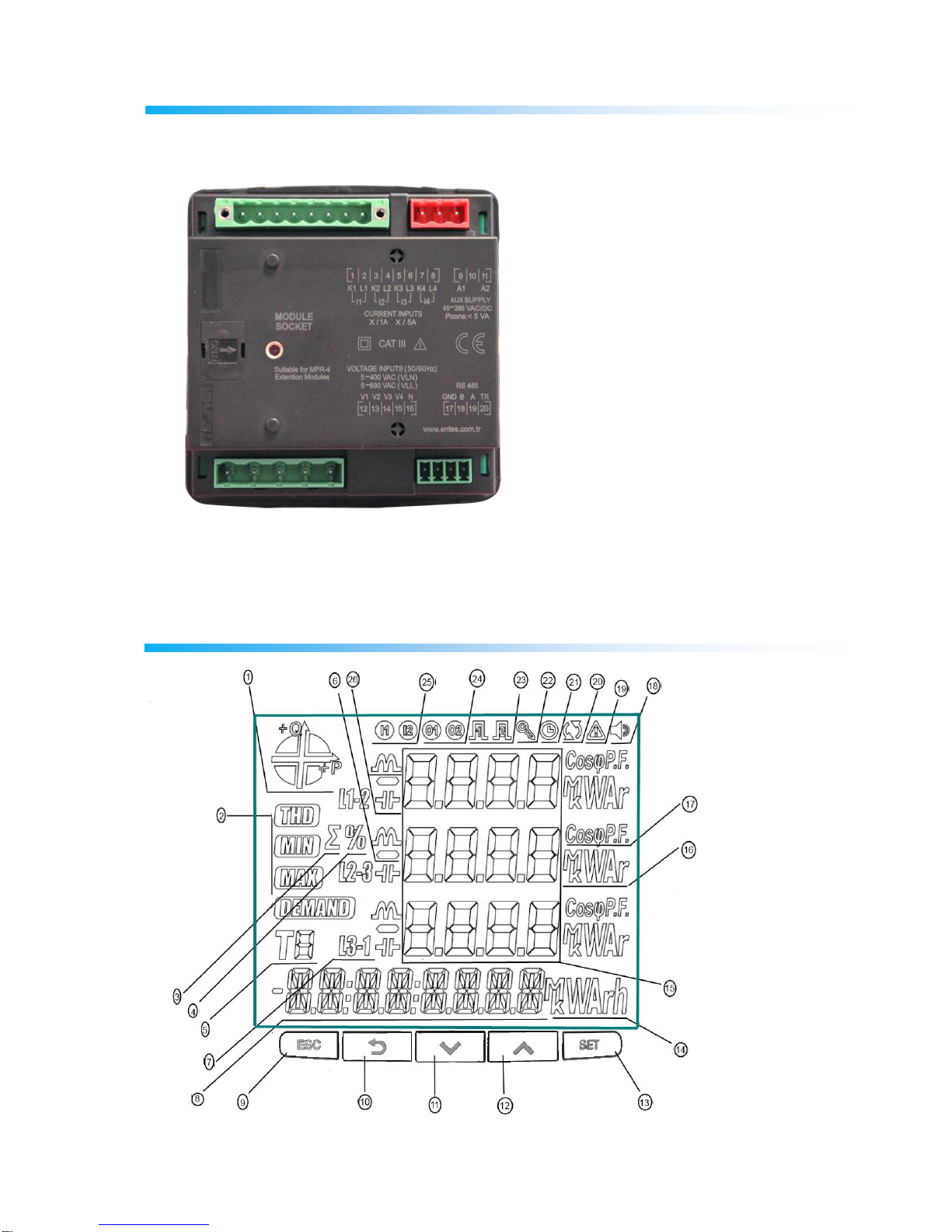
Overview
7
Terminals
Front Panel

8
1 –Indicates on which quadrant the network is operating.
2 –Indicates that the corresponding screen is one of THD, MIN, MAX or DEMAND screens.
3 –Indicates the total screen. (I.e. ΣTHD)
4 –Indicates the percent values.
5 –Indicates for which tariff the energy measurement is.
6 –Indicates negative value.
7 –Indicates L1, L2, L3 and L1-2, L2-3 and L3-1 measurements.
8 –Indicates energy value or time.
14 –Indicates the unit of the energy value
15 –Displays the measured values of the corresponding screen.
16 –Indicates the unit of the measured values.
17 –Indicates whether the value is CosØ or Power Factor.
18 –Indicates whether the alarm is active or not.
19 –Indicates a warning.
20 –Indicates a connection error.
21 –Indicates that the alarm clock is active.
22 –Indicates that the device is locked.
23 –Indicates which pulse output is active.
24 –Indicates which digital output is active.
25 –Indicates which digital input is active.
26 –Indicates whether the measurement is inductive or reactive.
Button Functions
In addition to their main functions, the 5 buttons on the front panel can be used as shortcut buttons for
easily reaching screens.
ESC button (9): It has 3 main functions:
Exiting from any menu is done by pressing ESC button.
While on measuring screen: As seen on the symbols (V I F) above the button, it is used to
browse between voltage, current and frequency measurement screens.
While on measuring screen: As seen on the symbols (Event) below the button, event screen is
reached when pressed for 3 seconds.
BACK Button (10) : It has 3 main functions:
While on measuring screen: As seen on the symbols (P PF) above the button, it is used to
browse between active power, reactive power, apparent power, power factor and Cos φ
measurement screens.
It is used to select the previous digit while entering a numerical value in the menu or to browse
back to a previous menu level.
While on measuring screen: As seen on the symbols (Test) below the button, connection control
is reached when pressed for 3 seconds.
Down Button (11) : It has 2 main functions:
While on measuring screen: As seen on the symbols (E Clock) above the button, it is used to
browse between import/export active energy consumption, reactive energy consumption, tariff
and time information screens.
While on menu screens: It is used to browse between menu options and to decrease a value
during adjustment.

9
Up Button (12) : It has 2 main functions:
While on measuring screen: As seen on the symbols (THD H) above the button, it is used to
browse between THDV, THDI and individual harmonic measurement screens.
While on menu screens: It is used to browse between menu options and to increase a value
during adjustment.
SET Button (13) : It has 3 main functions:
It provides access to menu screens when pressed for 3 seconds. When the PIN is active, a
password is asked before entering the menu. After the correct password is entered, access
to menu is allowed.
It is used to reach the desired adjustment screen and to save the changed settings. Pressing the
button is enough for this operation.
While on measuring screen: It is used to browse between Min, Max, Demand and Max Demand
screens.
Terminal Structure
1) 45-265 VAC Supply Input 3 terminal connections (2 pins)
2) Current measuring input terminal block (8 pins): L1 L2 L3 ve N
3) Voltage measuring input terminal block (5 pins): L1 L2 L3 L4 (Earth) and N
4) RS-485 terminal block (4 pins)
Module Input:
Digital Input/Output
4 digital outputs
4 digital inputs
Relay Output
2 relay outputs
4 digital inputs
Analog Output
2x 0/4 –20mA circuit or
2x 0/2 –10V circuit
10
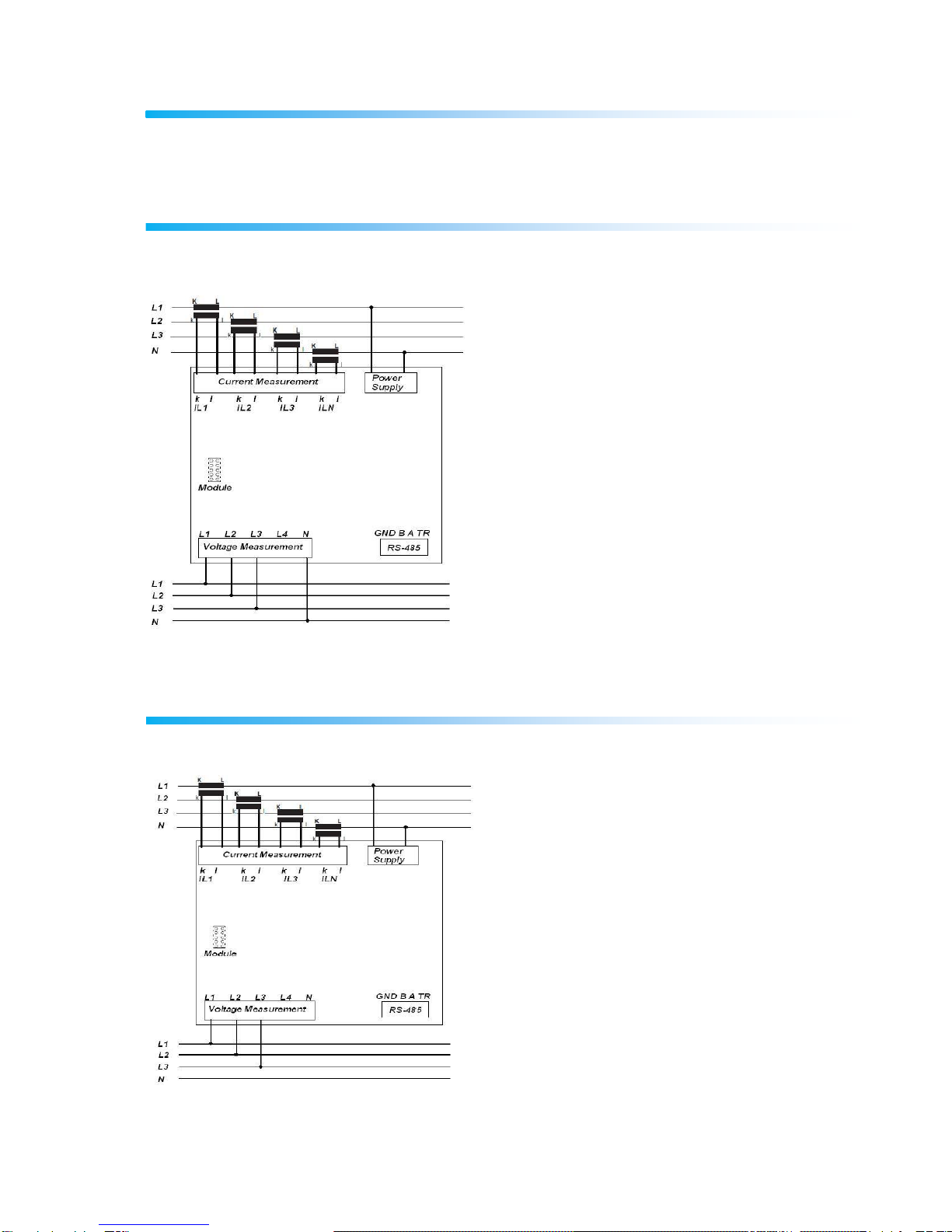
INSTALLATION
Device has 5 different connection configurations. These configurations are explained with diagrams
below:
3P4W (3 Phase with Neutral) Connection
For this configuration, four voltage connections (including neutral line) and four current connections are
used.
3P3W (3 Phase without Neutral) Connection
For this configuration, three voltage connections and four current connections are used.

11
Aron without Neutral Connection
For this configuration, three voltage connections and two current connections are used.
3P4W BLN (3 Phase Balanced with
Neutral) Connection
For this configuration, four voltage connections and one current connection is used.
The device shows the same current value, which is measured from the first phase, for the unconnected
phases.

12
3P3W BLN (3 Phase Balanced without
Neutral) Connection
For this configuration, three voltage connections and one current connection is used.
The device shows the same current value, which is measured from the first phase, for the unconnected
phases.

13
Connection Test
After finishing device connections, you can check the connection that you’ve done by using the automatic
test function.
When you press the BACK button for 3 seconds, it switches to test mode. During this mode, at least 20%
of the nominal voltage must be applied to the voltage measuring inputs, at least 10% of the nominal
current must be applied to the current measuring inputs and the angle difference between current and
voltage inputs must be less than 30 degrees. These test conditions must be met.
During connection test, the device controls the connections and it can correct them internally or it can
leave the physical correction to the user.
If there’s an error between voltage inputs, it can only be corrected by changing physical connections.
If you encounter Error 12, make sure that all connections are done and minimum current/voltage values
are applied to the device.
On the following table, possible connection errors that may be encountered during connection test and
their corresponding error codes that are displayed on the device screen.
Test Error Code
Test Code Description
0
All connections are correct
1
Phase-1 current direction is reversed
2
Phase-2 current direction is reversed
3
Phase-3 current direction is reversed
4
Phase-1 and Phase-2 voltage connections are reversed
5
Phase-1 and Phase-3 voltage connections are reversed
6
Phase-2 and Phase-3 voltage connections are reversed
7
Voltage connection phase sequence will be changed as L1,L2,L3 - L3,L1,L2.
8
Voltage connection phase sequence will be changed as L3,L2,L1 - L3,L1,L2.
9
CT-1, CT-2 will be swapped.
10
CT-1, CT-3 will be swapped.
11
CT-2, CT-3 will be swapped.
12
Test conditions are not met.
Line Termination Resistor
Line termination resistors are used when communication line length is longer than 10 metres. Please
short terminals GND and TR to enhance communication performance in case of multiple devices on the
same network.
14
OPERATING INSTRUCTIONS
Measurement Screens
Measurement screens, which can be accessed by pressing the related buttons, are explained in this
section.
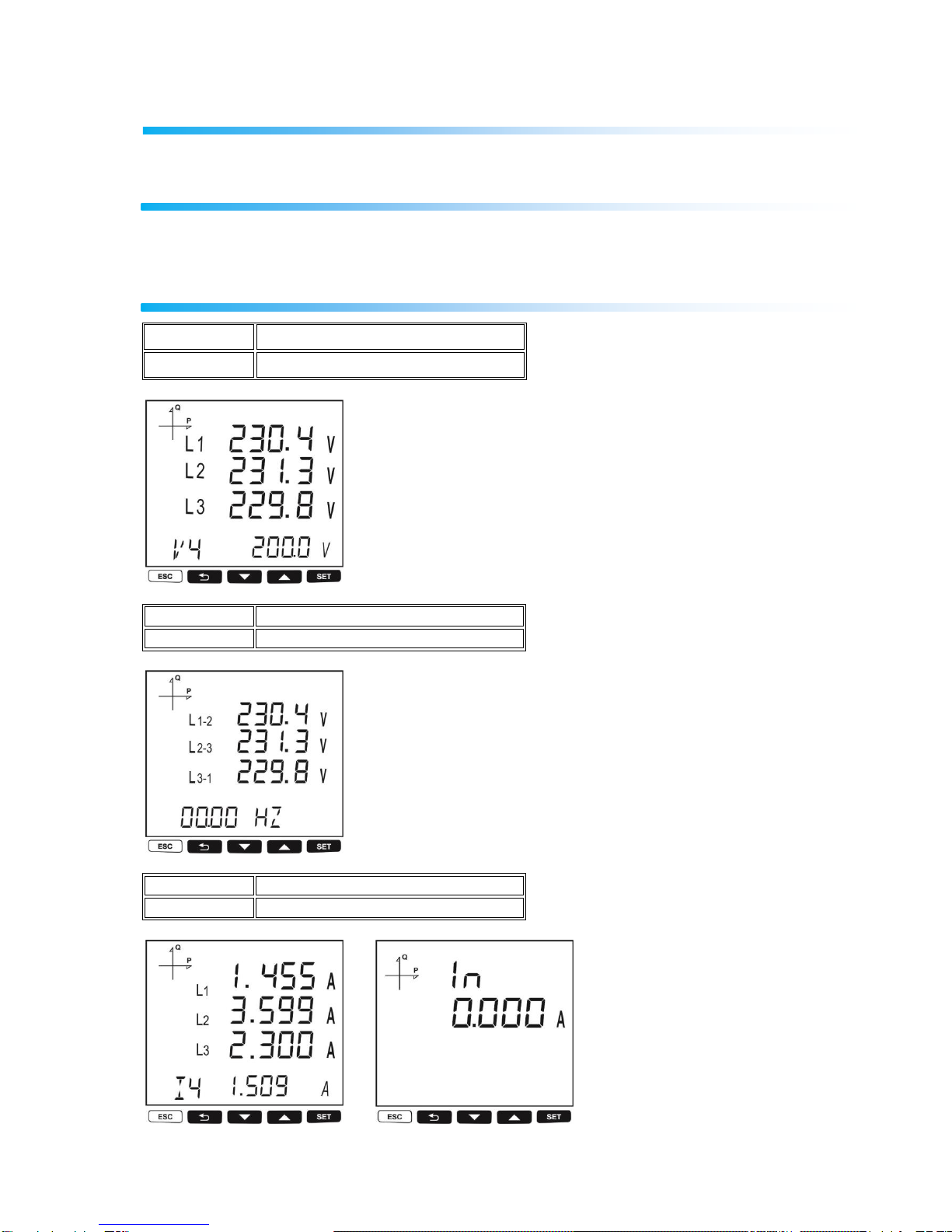
Current, Voltage and Frequency Screens
BUTTON NAME
DISPLAYED MEASUREMENT SCREEN
ESC (VIF)
VOLTAGE (L-N)
BUTTON NAME
DISPLAYED MEASUREMENT SCREEN
ESC (VIF)
VOLTAGE (L-L)
BUTTON NAME
DISPLAYED MEASUREMENT SCREEN
ESC (VIF)
CURRENT
15
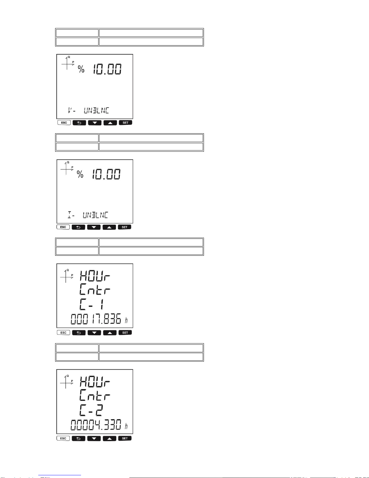
BUTTON NAME
DISPLAYED MEASUREMENT SCREEN
ESC (VIF)
V- UNBALANCE
BUTTON NAME
DISPLAYED MEASUREMENT SCREEN
ESC (VIF)
I- UNBALANCE
BUTTON NAME
DISPLAYED MEASUREMENT SCREEN
ESC (VIF)
WORK HOUR COUNTER 1
BUTTON NAME
DISPLAYED MEASUREMENT SCREEN
ESC (VIF)
WORK HOUR COUNTER 2
16
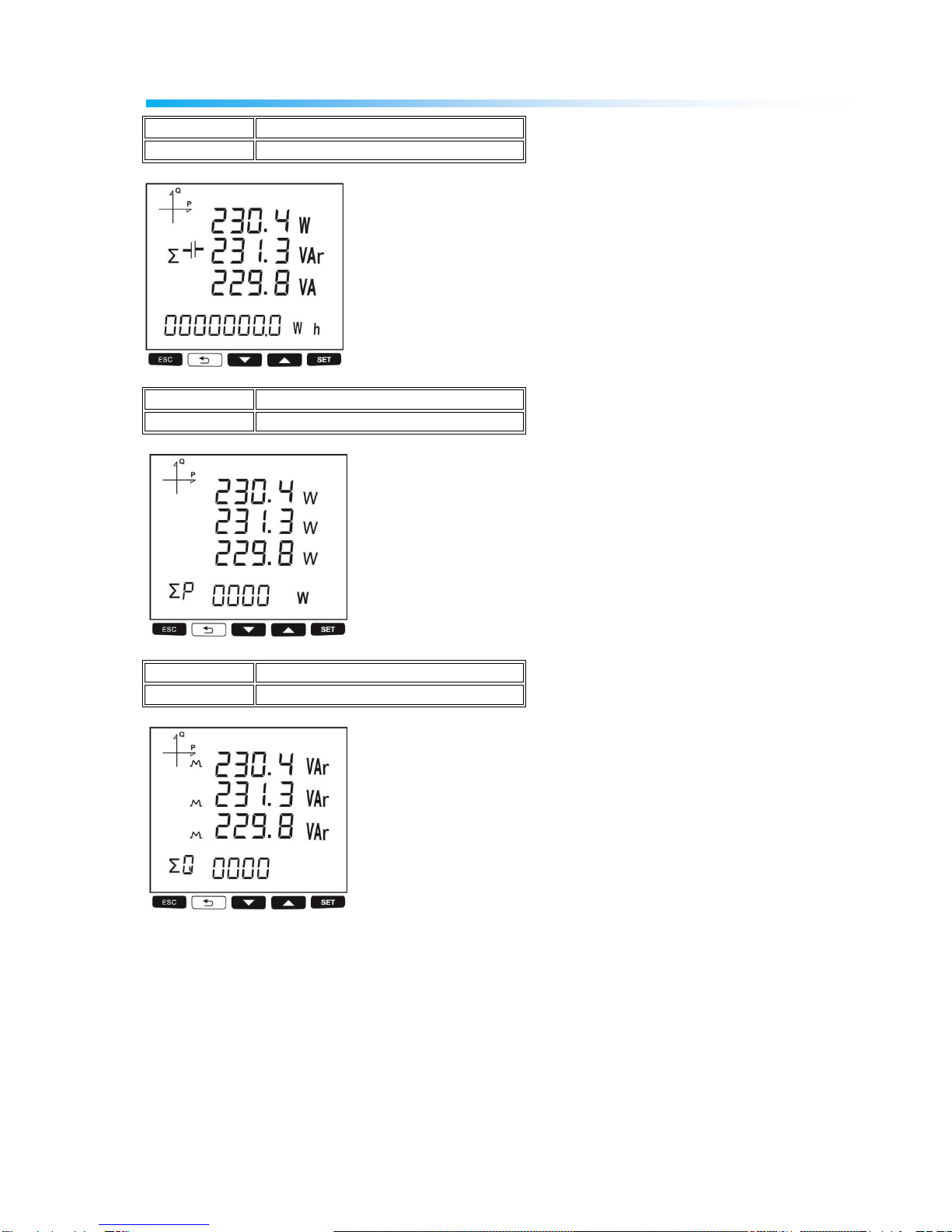
Power and Power Factor Screens
BUTTON NAME
DISPLAYED MEASUREMENT SCREEN
BACK (P PF)
TOTAL POWER
BUTTON NAME
DISPLAYED MEASUREMENT SCREEN
BACK (P PF)
ACTIVE POWER
BUTTON NAME
DISPLAYED MEASUREMENT SCREEN
BACK (P PF)
REACTIVE POWER
17
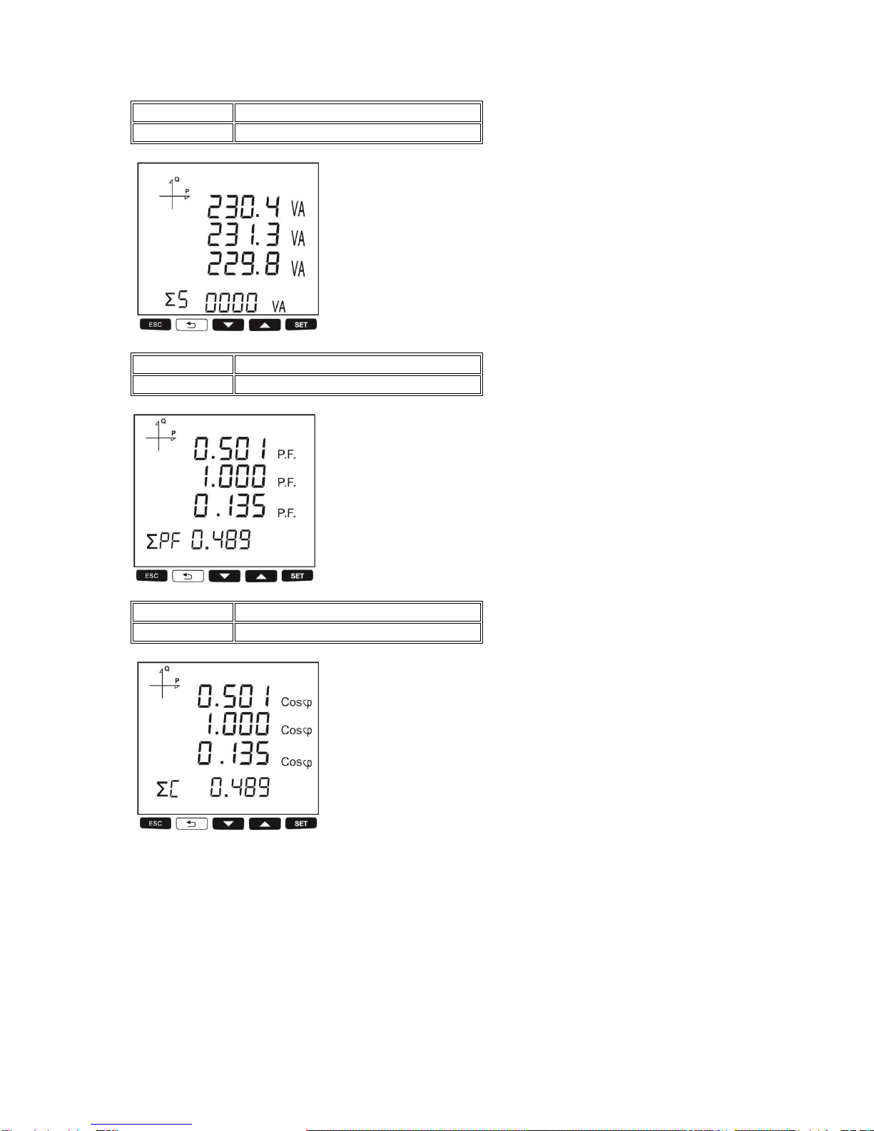
BUTTON NAME
DISPLAYED MEASUREMENT SCREEN
BACK (P PF)
APPARENT POWER
BUTTON NAME
DISPLAYED MEASUREMENT SCREEN
BACK (P PF)
POWER FACTOR
BUTTON NAME
DISPLAYED MEASUREMENT SCREEN
BACK (P PF)
COS φ

18
Energy and Time Screens
BUTTON NAME
DISPLAYED MEASUREMENT SCREEN
DOWN
Import Active Energy
BUTTON NAME
DISPLAYED MEASUREMENT SCREEN
DOWN
Export Active Energy
BUTTON NAME
DISPLAYED MEASUREMENT SCREEN
DOWN
Import Reactive Energy

19
BUTTON NAME
DISPLAYED MEASUREMENT SCREEN
DOWN
Export Reactive Energy
BUTTON NAME
DISPLAYED MEASUREMENT SCREEN
DOWN
Apparent Energy
BUTTON NAME
DISPLAYED MEASUREMENT SCREEN
DOWN
Active Energy in Total Tariff

20
BUTTON NAME
DISPLAYED MEASUREMENT SCREEN
DOWN
Active Energy in Active Tariff
BUTTON NAME
DISPLAYED MEASUREMENT SCREEN
DOWN
Energy Values for each Programmed Tariff (T1, T2, T3, T4, T5, T6, T7, T8, TG)
BUTTON NAME
DISPLAYED MEASUREMENT SCREEN
DOWN
Time
This manual suits for next models
4
Table of contents
Other Entes Measuring Instrument manuals

Entes
Entes EVM-05C User manual

Entes
Entes MPR-3 Series User manual

Entes
Entes EVM-3 Instruction manual

Entes
Entes EVM-R3 User manual

Entes
Entes EMG Series User manual

Entes
Entes MPR-4 Series User manual

Entes
Entes MPR-32 User manual

Entes
Entes DCV-10 User manual

Entes
Entes MPR-1 Series User manual

Entes
Entes EPR-04 Instruction manual

Entes
Entes MPR-53S User manual

Entes
Entes MPR-53CS User manual

Entes
Entes EVM-15 User manual

Entes
Entes EPM-4A User manual

Entes
Entes EMK-01 User manual

Entes
Entes MPR-4 Series User manual

Entes
Entes EVM-R3 User manual

Entes
Entes EVM-3S User manual

Entes
Entes ES3 Series User manual

Entes
Entes DCA-10 User manual


