ABB COPA-XM 3000 Series User manual

INSTRUCTION MANUAL
MAGNETIC FLOWMETERS
10DX3111/3311 Design Level E
Sizes 1⁄2through 12 Inches
COPA-XM
and MAG-X
SERIES 3000 MAGNETIC FLOWMETER
PN25013

The following are trademarks of ABB Inc.:
COPA-XM
MAG-X®
The following is a registered trademark of Du Pont:
TEFLON®
TEFZEL®
The following is a trademark of Haynes International Incorporated:
HASTELLOY
The following is a registered trademark of Rosemount Incorporated:
HART®
WARNING notices as used in this manual apply to hazards or unsafe practices which could result in
personal injury or death.
CAUTION notices apply to hazards or unsafe practices which could result in property damage.
NOTES highlight procedures and contain information which assist the operator in understanding the
information contained in this manual.
All software, including design, appearance, algorithms and source codes, is copyrighted by ABB
Inc. and is owned by ABB Inc. or its suppliers.
WARNING
POSSIBLE PROCESS UPSETS
Maintenance must be performed only by qualified personnel and only after securing equipment
controlled by this product. Adjusting or removing this product while it is in the system may
upset the process being controlled. Some process upsets may cause injury or damage.
NOTICE
The information contained in this document is subject to change without notice.
ABB Inc., its affiliates, employees, and agents, and the authors of and contributors to this
publication specifically disclaim all liabilities and warranties, express and implied (including
warranties of merchantability and fitness for a particular purpose), for the accuracy, currency,
completeness, and/or reliability of the information contained herein and/or for the fitness for any
particular use and/or for the performance of any material and/or equipment selected in whole or
part with the user of/or in reliance upon information contained herein. Selection of materials
and/or equipment is at the sole risk of the user of this publication.
This document contains proprietary information of ABB Inc., and is issued in strict confidence.
Its use, or reproduction for use, for the reverse engineering, development or manufacture of
hardware or software described herein is prohibited. No part of this document may be
photocopied or reproduced without the prior written consent of ABB Inc.
Copyright 2003 ABB Inc. [April, 2003]

Table of Contents
SAFETY SUMMARY . . . . . . . . . . . . . . . . . . . . . . . . . . . . . . . . . . . . . . . . . . . . . . . . . . . . . I
READ FIRST . . . . . . . . . . . . . . . . . . . . . . . . . . . . . . . . . . . . . . . . . . . . . . . . . . . . . . . . . .III
1.0 INTRODUCTION . . . . . . . . . . . . . . . . . . . . . . . . . . . . . . . . . . . . . . . . . . . . . . . . . . 1-1
1.1 General. . . . . . . . . . . . . . . . . . . . . . . . . . . . . . . . . . . . . . . . . . . . . . . . . . . . . . . . . . . . . . . . . . . . . 1-1
1.1.1 Description . . . . . . . . . . . . . . . . . . . . . . . . . . . . . . . . . . . . . . . . . . . . . . . . . . . . . . . . . . . . . 1-1
1.1.2 Construction . . . . . . . . . . . . . . . . . . . . . . . . . . . . . . . . . . . . . . . . . . . . . . . . . . . . . . . . . . . . 1-1
1.2 Model Number Breakdown. . . . . . . . . . . . . . . . . . . . . . . . . . . . . . . . . . . . . . . . . . . . . . . . . . . . . . 1-3
1.2.1 Model 10DX3111. . . . . . . . . . . . . . . . . . . . . . . . . . . . . . . . . . . . . . . . . . . . . . . . . . . . . . . . . 1-4
1.2.2 Model 10DX3311A/S . . . . . . . . . . . . . . . . . . . . . . . . . . . . . . . . . . . . . . . . . . . . . . . . . . . . . 1-6
1.3 Specifications . . . . . . . . . . . . . . . . . . . . . . . . . . . . . . . . . . . . . . . . . . . . . . . . . . . . . . . . . . . . . . . . 1-8
2.0 INSTALLATION . . . . . . . . . . . . . . . . . . . . . . . . . . . . . . . . . . . . . . . . . . . . . . . . . . . 2-1
2.1 Inspection . . . . . . . . . . . . . . . . . . . . . . . . . . . . . . . . . . . . . . . . . . . . . . . . . . . . . . . . . . . . . . . . . . . 2-1
2.2 Meter Handling . . . . . . . . . . . . . . . . . . . . . . . . . . . . . . . . . . . . . . . . . . . . . . . . . . . . . . . . . . . . . . . 2-2
2.3 Location . . . . . . . . . . . . . . . . . . . . . . . . . . . . . . . . . . . . . . . . . . . . . . . . . . . . . . . . . . . . . . . . . . . . 2-5
2.4 Mounting. . . . . . . . . . . . . . . . . . . . . . . . . . . . . . . . . . . . . . . . . . . . . . . . . . . . . . . . . . . . . . . . . . . 2-12
2.4.1 Orientation . . . . . . . . . . . . . . . . . . . . . . . . . . . . . . . . . . . . . . . . . . . . . . . . . . . . . . . . . . . . 2-12
2.4.2 Pipe Connections . . . . . . . . . . . . . . . . . . . . . . . . . . . . . . . . . . . . . . . . . . . . . . . . . . . . . . . 2-12
2.5 Grounding Procedure . . . . . . . . . . . . . . . . . . . . . . . . . . . . . . . . . . . . . . . . . . . . . . . . . . . . . . . . . 2-15
2.5.1 General . . . . . . . . . . . . . . . . . . . . . . . . . . . . . . . . . . . . . . . . . . . . . . . . . . . . . . . . . . . . . . . 2-15
2.5.2 Conductive Pipeline . . . . . . . . . . . . . . . . . . . . . . . . . . . . . . . . . . . . . . . . . . . . . . . . . . . . . 2-15
2.5.3 Non-Conductive or Electrically Insulated Pipeline . . . . . . . . . . . . . . . . . . . . . . . . . . . . . . 2-16
2.6 Electrical Interconnection . . . . . . . . . . . . . . . . . . . . . . . . . . . . . . . . . . . . . . . . . . . . . . . . . . . . . . 2-18
2.7 Conduit Seal and Pressure Relief . . . . . . . . . . . . . . . . . . . . . . . . . . . . . . . . . . . . . . . . . . . . . . . 2-18
3.0 START-UP and OPERATION . . . . . . . . . . . . . . . . . . . . . . . . . . . . . . . . . . . . . . . . 3-1
4.0 FUNCTIONAL DESCRIPTION . . . . . . . . . . . . . . . . . . . . . . . . . . . . . . . . . . . . . . . 4-1
4.1 Basic Operating Principle. . . . . . . . . . . . . . . . . . . . . . . . . . . . . . . . . . . . . . . . . . . . . . . . . . . . . . . 4-1
4.1.1 Signal Voltage Generation . . . . . . . . . . . . . . . . . . . . . . . . . . . . . . . . . . . . . . . . . . . . . . . . . 4-1
4.1.2 Magnet Coil Drive Circuits . . . . . . . . . . . . . . . . . . . . . . . . . . . . . . . . . . . . . . . . . . . . . . . . . 4-2
4.1.3 Volumetric Flow Rate Measurement. . . . . . . . . . . . . . . . . . . . . . . . . . . . . . . . . . . . . . . . . . 4-2
4.2 Operating Characteristics. . . . . . . . . . . . . . . . . . . . . . . . . . . . . . . . . . . . . . . . . . . . . . . . . . . . . . . 4-3
4.2.1 Liquid Variables . . . . . . . . . . . . . . . . . . . . . . . . . . . . . . . . . . . . . . . . . . . . . . . . . . . . . . . . . 4-3
4.2.1.1 Liquid Conductivity. . . . . . . . . . . . . . . . . . . . . . . . . . . . . . . . . . . . . . . . . . . . . . . . . 4-3
4.2.1.2 Liquid Temperature . . . . . . . . . . . . . . . . . . . . . . . . . . . . . . . . . . . . . . . . . . . . . . . . 4-5
4.2.1.3 Other Liquid Variables . . . . . . . . . . . . . . . . . . . . . . . . . . . . . . . . . . . . . . . . . . . . . . 4-5
4.2.2 Metering Characteristics . . . . . . . . . . . . . . . . . . . . . . . . . . . . . . . . . . . . . . . . . . . . . . . . . . . 4-5
4.3 Circuit Description . . . . . . . . . . . . . . . . . . . . . . . . . . . . . . . . . . . . . . . . . . . . . . . . . . . . . . . . . . . . 4-5
4.3.1 Primary Signals. . . . . . . . . . . . . . . . . . . . . . . . . . . . . . . . . . . . . . . . . . . . . . . . . . . . . . . . . . 4-5
4.3.2 Constant Meter Capacity (CMC) PC Assembly . . . . . . . . . . . . . . . . . . . . . . . . . . . . . . . . . 4-6
Series 10DX3000 Magnetic Flowmeter Instruction Manual
i

4.4 Jumper Selections. . . . . . . . . . . . . . . . . . . . . . . . . . . . . . . . . . . . . . . . . . . . . . . . . . . . . . . . . . . . 4-7
4.4.1 Integral Converter . . . . . . . . . . . . . . . . . . . . . . . . . . . . . . . . . . . . . . . . . . . . . . . . . . . . . . . 4-7
4.4.2 Remote Converter . . . . . . . . . . . . . . . . . . . . . . . . . . . . . . . . . . . . . . . . . . . . . . . . . . . . . . . 4-9
4.5 Terminal Numbering . . . . . . . . . . . . . . . . . . . . . . . . . . . . . . . . . . . . . . . . . . . . . . . . . . . . . . . . . . 4-9
5.0 MAINTENANCE . . . . . . . . . . . . . . . . . . . . . . . . . . . . . . . . . . . . . . . . . . . . . . . . . . . 5-1
5.1 General . . . . . . . . . . . . . . . . . . . . . . . . . . . . . . . . . . . . . . . . . . . . . . . . . . . . . . . . . . . . . . . . . . . . 5-1
5.2 System Troubleshooting . . . . . . . . . . . . . . . . . . . . . . . . . . . . . . . . . . . . . . . . . . . . . . . . . . . . . . . 5-2
5.3 Static Test . . . . . . . . . . . . . . . . . . . . . . . . . . . . . . . . . . . . . . . . . . . . . . . . . . . . . . . . . . . . . . . . . . 5-3
5.3.1 Magnet Coil Check . . . . . . . . . . . . . . . . . . . . . . . . . . . . . . . . . . . . . . . . . . . . . . . . . . . . . . 5-3
5.3.1.1 Remote Model 10DX3111E. . . . . . . . . . . . . . . . . . . . . . . . . . . . . . . . . . . . . . . . . . 5-3
5.3.1.2 Integral Model 10DX3311E . . . . . . . . . . . . . . . . . . . . . . . . . . . . . . . . . . . . . . . . . . 5-3
5.3.2 Electrode Check . . . . . . . . . . . . . . . . . . . . . . . . . . . . . . . . . . . . . . . . . . . . . . . . . . . . . . . . 5-4
5.3.2.1 Full Pipe Test . . . . . . . . . . . . . . . . . . . . . . . . . . . . . . . . . . . . . . . . . . . . . . . . . . . . 5-4
5.3.2.2 Empty Pipe Test . . . . . . . . . . . . . . . . . . . . . . . . . . . . . . . . . . . . . . . . . . . . . . . . . . 5-4
5.3.2.3 Electrode Voltage Test . . . . . . . . . . . . . . . . . . . . . . . . . . . . . . . . . . . . . . . . . . . . . 5-5
6.0 PARTS LIST . . . . . . . . . . . . . . . . . . . . . . . . . . . . . . . . . . . . . . . . . . . . . . . . . . . . . . 6-1
Table List
TABLE 1-1. MAXIMUM LIQUID TEMPERATURE . . . . . . . . . . . . . . . . . . . . . . . . . . . 1-10
TABLE 1-2. PRESSURE RATING, MPa (psig) . . . . . . . . . . . . . . . . . . . . . . . . . . . . . 1-10
TABLE 1-3. VACUUM LIMIT . . . . . . . . . . . . . . . . . . . . . . . . . . . . . . . . . . . . . . 1-11
TABLE 1-4. METER CAPACITY VALUES . . . . . . . . . . . . . . . . . . . . . . . . . . . . . . . 1-11
TABLE 2-1. METER WEIGHTS . . . . . . . . . . . . . . . . . . . . . . . . . . . . . . . . . . . . 2-2
TABLE 2-2. CONTINUOUS SUBMERGENCE WEIGHT FACTORS . . . . . . . . . . . . . . . . . . 2-2
TABLE 2-3. TORQUE RECOMMENDATIONS (ANSI) . . . . . . . . . . . . . . . . . . . . . . . . . 2-22
TABLE 2-4. TORQUE RECOMMENDATIONS (DIN) . . . . . . . . . . . . . . . . . . . . . . . . . 2-22
TABLE 4-1. 686B762U02 PCB JUMPER FUNCTIONS . . . . . . . . . . . . . . . . . . . . . . . . 4-7
TABLE 6-1. FLANGE GASKETS FOR METER BODY . . . . . . . . . . . . . . . . . . . . . . . . . 6-1
TABLE 6-2. PROTECTOR PLATES FOR TEFLON & TEFZEL LINED METERS . . . . . . . . . . . 6-2
TABLE 6-3. LINER PROTECTOR/GROUNDING RINGS FOR TEFLON & TEFZEL LINED METERS 6-2
TABLE 6-4. GROUNDING RINGS - SIZES 1/2 THROUGH 4 INCHES . . . . . . . . . . . . . . . . 6-3
TABLE 6-5. GROUNDING RINGS - SIZES 6 THROUGH 12 INCHES . . . . . . . . . . . . . . . . 6-3
TABLE 6-6. CONVERTER BASE AND JUNCTION BOX GASKETS . . . . . . . . . . . . . . . . . 6-4
TABLE 6-7. HARDWARE . . . . . . . . . . . . . . . . . . . . . . . . . . . . . . . . . . . . . . . 6-4
Series 10DX3000 Magnetic Flowmeter Instruction Manual
ii

Figure List
FIGURE 1-1. EXPLOSION-PROOF / CONTINUOUS SUBMERGENCE METER . . . . . . . . . . . 1-2
FIGURE 2-1. PROTECTOR PLATES FOR TEFLON LINERS . . . . . . . . . . . . . . . . . . . . . 2-3
FIGURE 2-2. PROPER HOISTING METHOD . . . . . . . . . . . . . . . . . . . . . . . . . . . . . . 2-4
FIGURE 2-3. OUTLINE DIMENSIONS, 1/2-4 INCH INTEGRAL CONVERTER WITH ANSI FLANGES 2-6
FIGURE 2-4. OUTLINE DIMENSIONS, 6-12 INCH INTEGRAL CONVERTER WITH ANSI FLANGES 2-7
FIGURE 2-5. OUTLINE DIMENSIONS, 1/2-4 INCH INTEGRAL CONVERTER WITH DIN FLANGES . 2-8
FIGURE 2-6. OUTLINE DIMENSIONS, 6-12 INCH INTEGRAL CONVERTER WITH DIN FLANGES . 2-9
FIGURE 2-7. OUTLINE DIMENSIONS, 1/2-4 INCH REMOTE CONVERTER WITH ANSI FLANGES . 2-10
FIGURE 2-8. OUTLINE DIMENSIONS, 6-12 INCH REMOTE CONVERTER WITH ANSI FLANGES . 2-11
FIGURE 2-9. OUTLINE DIMENSIONS, 6-12 INCH REMOTE CONVERTER WITH ANSI FLANGES,
HI-TEMP . . . . . . . . . . . . . . . . . . . . . . . . . . . . . . . . . . . . . . . . . 2-12
FIGURE 2-10. OUTLINE DIMENSIONS, 1/2-4 INCH REMOTE CONVERTER WITH DIN FLANGES . 2-13
FIGURE 2-11. OUTLINE DIMENSIONS, 6-12 INCH REMOTE CONVERTER WITH DIN FLANGES . 2-14
FIGURE 2-12. OUTLINE DIMENSIONS, 6-12 INCH REMOTE CONVERTER WITH DIN FLANGES,
HI-TEMP . . . . . . . . . . . . . . . . . . . . . . . . . . . . . . . . . . . . . . . . . 2-15
FIGURE 2-13. OUTLINE DIMENSIONS, 1/2-4 INCH REMOTE CONVERTER WITH ANSI FLANGES,
CONTINUOUS SUBMERGENCE . . . . . . . . . . . . . . . . . . . . . . . . . . . . 2-16
FIGURE 2-14. OUTLINE DIMENSIONS, 6-12 INCH REMOTE CONVERTER WITH ANSI FLANGES,
CONTINUOUS SUBMERGENCE . . . . . . . . . . . . . . . . . . . . . . . . . . . . 2-17
FIGURE 2-15. OUTLINE DIMENSIONS, 1/2-4 INCH REMOTE CONVERTER WITH DIN FLANGES,
CONTINUOUS SUBMERGENCE . . . . . . . . . . . . . . . . . . . . . . . . . . . . 2-18
FIGURE 2-16. OUTLINE DIMENSIONS, 6-12 INCH REMOTE CONVERTER WITH DIN FLANGES,
CONTINUOUS SUBMERGENCE . . . . . . . . . . . . . . . . . . . . . . . . . . . . 2-19
FIGURE 2-17. RECOMMENDED PIPING ARRANGEMENT . . . . . . . . . . . . . . . . . . . . . . 2-21
FIGURE 2-18. BOLT TIGHTENING SEQUENCE . . . . . . . . . . . . . . . . . . . . . . . . . . . . 2-21
FIGURE 2-19 . GASKET LOCATIONS . . . . . . . . . . . . . . . . . . . . . . . . . . . . . . . . . 2-23
FIGURE 2-20. GROUNDING PROCEDURE; CONDUCTIVE PIPELINE . . . . . . . . . . . . . . . . 2-25
FIGURE 2-21. GROUNDING PROCEDURE; NON-CONDUCTIVE PIPELINE . . . . . . . . . . . . . 2-26
FIGURE 2-22. CONDUIT ENTRY SEAL INSTALLATION . . . . . . . . . . . . . . . . . . . . . . . . 2-27
FIGURE 3-1. TYPICAL REMOTE PRIMARY DATA TAG . . . . . . . . . . . . . . . . . . . . . . . . 3-1
FIGURE 3-2. TYPICAL INTEGRAL PRIMARY DATA TAG . . . . . . . . . . . . . . . . . . . . . . . 3-1
FIGURE 3-3. INTEGRALLY MOUNTED ENCLOSURE WITHOUT CONVERTER MODULE
[10DX3311E] . . . . . . . . . . . . . . . . . . . . . . . . . . . . . . . . . . . . . . . 3-2
FIGURE 3-4. REMOTE PRIMARY PCB ASSEMBLY IN GENERAL PURPOSE OR
FM CLASS I, DIV.2 HOUSING [10DX3111E] . . . . . . . . . . . . . . . . . . . . . . 3-3
FIGURE 3-5. EXPLOSION-PROOF PRIMARY FOR REMOTE MOUNTED SIGNAL CONVERTER . . 3-4
FIGURE 4-1. BASIC OPERATING PRINCIPLE . . . . . . . . . . . . . . . . . . . . . . . . . . . . . 4-1
FIGURE 4-2. SIMPLIFIED MAGMETER SYSTEM BLOCK DIAGRAM . . . . . . . . . . . . . . . . . 4-6
FIGURE 4-3. 686B762U02 PRIMARY BOARD ASSEMBLY . . . . . . . . . . . . . . . . . . . . . . 4-8
FIGURE 4-4. 10DX3111E REMOTE PRIMARY PCB ASSEMBLIES . . . . . . . . . . . . . . . . . . 4-9
Series 10DX3000 Magnetic Flowmeter Instruction Manual
iii
SAFETY SUMMARY
GENERAL
WARNINGS POSSIBLE PROCESS UPSETS
Maintenance must be performed only by qualified personnel and
only after securing equipment controlled by this product. Adjusting
or removing this product while it is in the system may upset the
process being controlled. Some process upsets may cause injury or
damage.
RETURN OF EQUIPMENT
All Flowmeters and/or Signal Converters being returned to the fac-
tory for repair must be free of any hazardous materials (acids,
alkalis, solvents, etc.). A Material Safety Data Sheet (MSDS) for all
process liquids must accompany returned equipment. Contact the
factory for authorization prior to returning equipment.
INSTRUCTION MANUALS
Do not install, maintain or operate this equipment without reading,
understanding and following the proper instructions and manuals,
otherwise injury or damage may result.
ELECTRICAL SHOCK HAZARD
Equipment powered by AC line voltage presents a potential electric
shock hazard to the user. Make certain that the system power is
disconnected from the operating branch circuit before attempting
electrical interconnections or service.
SPECIFIC
WARNINGS ELECTRICAL SHOCK HAZARD. Equipment powered by an AC line
voltage presents a potential electric shock hazard. Servicing of the
Magnetic Flow meter or Signal Converter should only be attempted
by a qualified electronics technician. (pg. 6-2)
ELECTRICAL SHOCK HAZARD. Equipment powered by an AC line
voltage presents a potential electric shock hazard. Make certain that
the system power is disconnected before making the following ohm-
meter checks. (pg. 6-3)
SPECIFIC
CAUTIONS Do not use a DC ohmmeter for this measurement as polarization
effects will produce completely erroneous data. (pg. 4-3)
Some of the IC devices used in the signal converter are static
sensitive and may be damaged by improper handling. When adjust-
ing or servicing the signal converter, use of a grounded wrist strap
is recommended to prevent inadvertant damage to the integral solid
state circuitry. (pg. 6-1)
Series 10DX3000 Magnetic Flowmeter Instruction Manual
II

GÉNÉRAUX
AVERTISSEMENTS PROBLÈMES POTENTIELS. La maintenance doit être réalisée
par du personnel qualifié et seulement après avoir sécurisé
les équipements contrôlés par ce produit. L’ajustement ou le
démontage de ce produit lorsqu’il est lié au système peut
entraîner des dysfonctionnements dans le procédé qu’il con-
trôle. Ces dysfonctionnements peuvent entraîner des bles-
sures ou des dommages.
RETOUR D’ÉQUIPEMENT. Tout débitmètre et(ou) convert-
isseur retourné à ABB pour réparation doit être exempt de
toute trace de produit dangereux (acide, base, solvant, …).
Un certificat de sécurité matériel doit être joint pour tous les
liquides utilisés dans le procédé. Contacter ABB pour autori-
sation avant renvoi du matériel.
MANUEL DE MISE EN ROUTE. Ne pas installer, maintenir ou
utiliser cet équipement sans avoir lu, compris et suivi les
instructions et manuels de ABB, dans le cas contraire il y a
risque d’entraîner blessures ou dommages.
RISQUE DE CHOC ÉLECTRIQUE
Les équipements alimentés en courant alternatif constituent
un risque de choc électrique potentiel pour l’utilisateur. As-
surez-vous que les câbles d’alimentation amont sont décon-
nectés avant de procéder à des branchements, des essais ou
tests.
SPÉCIFIQUES
AVERTISSEMENTS RISQUE DE CHOC ÉLECTRIQUE
Les équipements alimentés en courant alternatif constituent
un risque de choc électrique potentiel. La maintenance sur
des équipements électromagnétiques ou des convertisseurs
doit être effectuée par des techniciens qualifiés. (pg. 6-2)
RISQUE DE CHOC ÉLECTRIQUE
Les équipements alimentés en courant alternatif constituent
un risque de choc électrique potentiel. Assurez-vous que la
puissance est déconnectée avant de procéder aux mesures
de résistance suivantes. ( pg 6-3)
SPÉCIFIQUES
ATTENTIONS N’utilisez pas un ohmmètre de C.C pour cette mesure car les
effets de polarisation produiront des données complètement
incorrectes. (pg. 4-3)
Certains Circuits Intégrés utilisés dans le convertisseur sont
sensibles à l’électricité statique et peuvent être endommagés
par une mauvaise manipulation. Pendant l’ajustement ou la
maintenance d’un convertisseur, l’utilisation d’un bracelet
antistatique est recommandé pour éviter la destruction par
inadvertance d’un circuit intégré. (pg. 6-1)
Series 10DX3000 Magnetic Flowmeter Instruction Manual
I

READ FIRST
WARNING
INSTRUCTION MANUALS
Do not install, maintain, or operate this equipment without reading,
understanding and following the proper manufacturer’s instructions and
manuals, otherwise injury or damage may result.
RETURN OF EQUIPMENT
All Flowmeters and/or Signal Converters being returned to the
manufacturer for repair must be free of any hazardous materials (acids,
alkalis, solvents, etc). A Material Safety Data Sheet (MSDS) for all
process liquids must accompany returned equipment. Contact the
manufacturer for authorization prior to returning equipment.
Read these instructions before starting installation;
save these instructions for future reference.
Contacting the factory
Should assistance be required with any of the manufacturer’s products, contact the following:
Telephone:
Automation Services Call Center
1-800-HELP-365
E-Mail:
ins.techsuppor[email protected]
Series 10DX3000 Magnetic Flowmeter Instruction Manual
III

The NEMA 4X rating applies to the meter body and electronics enclosure only. The following
accessories (if supplied) may not meet NEMA 4X unless specifically ordered as NEMA 4X:
•meter flanges
•meter installation hardware: studs, nuts, bolts
•enclosure mounting hardware for pipe or wall mounting
•conduit hardware
This product is painted with a high performance epoxy paint. The corrosion protection provided by
this finish is only effective if the finish is unbroken. It is the users’ responsibility to "touch-up" any
damage that has occurred to the finish during shipping or installation of the product. Special attention
must be given to: meter flange bolting, pipe mounting of electronics, conduit entries and covers that
are removed to facilitate installation or repair. For continued corrosion protection throughout the
product life, it is the users’ responsibility to maintain the product finish. Incidental scratches and other
finish damage must be repaired and promptly re-painted with approved touch-up paint. Provide the
model number and size of your product to the nearest factory representative to obtain the correct
touch-up paint.
Series 10DX3000 Magnetic Flowmeter Instruction Manual
IV

1.0 INTRODUCTION
1.1 General
1.1.1 Description
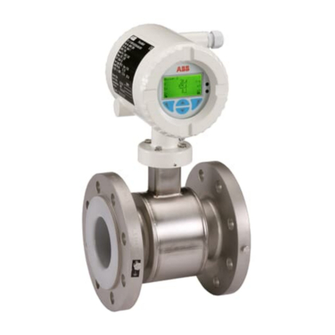
The Series 3000 Magnetic Flowmeter is a compact, volumetric, liquid flow rate detector that uses as
the process transducing method the characteristic of a conductive liquid to generate an induced
voltage when flowing through a magnetic field. The amplitude of the voltage produced is directly
proportional to the flow rate of the metered liquid.
Being a completely obstructionless metering instrument, the Series 3000 Magnetic Flowmeter can be
used to meter liquids without regard to heterogeneous consistency and is as independent of the
tendency to plug or foul as the pipeline in which it is mounted. An inherent advantage of obstruction-
less construction is that pressure losses are reduced to levels occurring in equivalent lengths of
equal diameter pipeline. This reduces or conserves pressure source requirements in new or existing
hydraulic lines as compared to other metering methods. The compact size of the meter results in a
light-weight unit which requires no additional support other than that used normally on pipe runs.
Short laying lengths minimize the need for altering existing pipe runs to accommodate metering. A
basic construction of corrosive resistant wetted parts and a variety of meter lining materials permit
metering of most corrosive and reactant liquids.
Factors such as liquid viscosity and density require no compensation and have no effect on the
measurement accuracy of the Magnetic Flowmeter. Metering limitations are confined to a minimum
threshold of electrical conductivity inherent to the liquid being metered. The degree of liquid conduc-
tivity has no effect upon metering accuracy as long as it is greater than this minimum level. Liquid
temperature is limited only to the extent that it may affect liquid conductivity and, like liquid pressure,
to the extent that it can not exceed the meter material specification limits.
The associated electronics package is called the Signal Converter and may be either integrally or
remotely mounted. Either an analog or a microprocessor signal converter may be used with the
Series 3000 Magnetic Flowmeter. The Flowmeter without the electronic package is used with a
remote mounted Signal Converter. A remotely mounted Signal Converter is recommended for any or
all of the following conditions:
•if the summation of ambient and process temperature is greater than 262oF
(110oC) for COPA-XM, the Signal Converter must be remotely mounted.
•vibrations above the specification given in Section 1.3
The Signal Converter also contains a magnet driver unit that is used to power the meter’s magnet
coils. The steady bipolar state magnetic field principle, referred to as the MAG-X®design concept,
provides optimum zero point stability at an optimized drive frequency.
For information concerning the Signal Converter, refer to the Signal Converter Instruction Manual.
1.1.2 Construction
The Series 3000 Magnetic Flowmeter consists of a flanged, stainless steel pipe spool which serves
as a meter body. A pair of flat magnet coils fit on opposite sides of the meter housing inner surface.
Permeable iron straps and pole pieces focus the magnetic field generated by the coils and provide a
flux return path.
Series 10DX3000 Magnetic Flowmeter Instruction Manual
1-1

Construction of the meter is dependent on
the type of insulating interior liner used. A
TEFLON®(PTFE) liner is inserted into the
spool and turned-out against the flange
faces. All other liner materials are bonded to
the interior and face of the pipe spool. For all
liner materials, two cylindrical electrodes are
mounted diametrically opposed within the
central portion of the meter body and are
completely insulated from the metal pipe.
The end surfaces of the electrodes are virtu-
ally flush with the inner surface of the insulat-
ing liner and come into contact with the liquid
to be metered.
The primary housing for the continuous sub-
mergence & explosion-proof design is differ-
ent from the other configurations in that it is
sealed with a round screw-on access cover.
The interior of this housing is filled with a
gelatin-like silicone rubber compound which
helps give the meter its waterproof rating.
The construction of this meter is shown in
FIGURE 1-1.
The NEMA 4X rating applies to the meter body and electronics enclosure only. The following
accessories (if supplied) may not meet NEMA 4X unless specifically ordered as NEMA 4X:
•meter flanges
•meter installation hardware: studs, nuts, bolts
•enclosure mounting hardware for pipe or wall mounting
•conduit hardware
NEMA 4X, Corrosion Resistant Finish
This product is painted with a high performance epoxy paint. The corrosion
protection provided by this finish is only effective if the finish is unbroken. It is the
users’ responsibility to "touch-up" any damage that may occur to the finish during
shipping or installation of the product. Special attention must be given to meter
flange bolting, pipe mounting of electronics, conduit entries and covers that are re-
moved to facilitate installation or repair. For continuing corrosion protection
throughout the product life, it is the users’ responsibility to maintain the product fin-
ish. Incidental scratches and finish damage must be repaired and promptly re-
painted with approved touch-up paint.
FIGURE 1-1. EXPLOSION-PROOF /
CONTINUOUS SUBMERGENCE METER
Series 10DX3000 Magnetic Flowmeter Instruction Manual
1-2

1.2 Model Number Breakdown
Refer to the data sheet or data tag on the equipment for the model number of the instrument
furnished. The details of a specific number are referenced on the following pages.
Series 10DX3000 Magnetic Flowmeter Instruction Manual
1-3

1.2.1 Model 10DX3111E
10DX3111 E______________
Engineering Reference
Obstructionless Remote Magnetic Flowmeter
Design Level
Remote with 50XM1000 Converter Electronics E
Meter Lay Length
Short Form (WMAG) D
Replacement for 10D1419 & 10D1465 E
Replacement for 10D1435 F
Other Z
Liner Material
Hard Rubber A
Polyurethane D
PTFE Teflon E
Neoprene L
TEFZEL N
Size
mm (inches)
15 (1/2) 07
25 (1) 09
40 (1-1/2) 11
50 (2) 12
80 (3) 14
100 (4) 15
150 (6) 17
200 (8) 18
250 (10) 19
300 (12) 20
Flange Standard Pressure Rating
DIN PN 10 C
DIN PN 16 D
DIN PN 25 E
DIN PN 40 F
ANSI Class 150 P
ANSI Class 300 Q
ANSI Class 600 R
ANSI Class 900 5
Flange Material
Carbon Steel 1
304 Stn. Steel 2
Protector Plate (TEFLON Liner only)
None Required A
316 Stn. Steel B
HASTELLOY C E
Electrode Type
Flush 2
Bullet Nose 3
Flush (Slurry Service) 7
Series 10DX3000 Magnetic Flowmeter Instruction Manual
1-4

1.2.1 Model 10DX3111E (continued)
10DX3111 E ______________
Electrode Material
316 Stn. Steel B
HASTELLOY®B C
HASTELLOY®C D
Titanium E
Tantalum F
Platinum / Iridium H
Zirconium L
Certification
Standard (None) A
FM Approved-Nonincendive for ClI, Div 2, Gp A,B,C & D; Electrodes Intrinsically Safe
for CII, Div 1, Gp A,B,C & D; Outdoor Hazardous Locations, NEMA 4X. Dust-
Ignitionproof Cl II, Div1, Gp E,F & G: Suitable for Cl III, Div 1, Accidental
Submergence, 30ft H2O/48h (9m H2O/48h)
K
FM Approved-Explosionproof for ClI, Div 1, Gp B,C & D; Dust-Ignitionproof Cl II,
Div 1, Gp E,F & G; Suitable for Cl III, Div 1; Electrodes Intrinsically Safe for CII, Div
1, Gp A,B,C & D; Outdoor Hazardous Locations, NEMA 4X
L
Enclosure Classification
IEC 529 IP 65, NEMA 4X 1
Accidental Submergence: IEC 529, IP 67, NEMA-4X. 33ft H2O/48h (10m H2O/48h) 2
Accidental Submergence: IEC 529, IP 67, NEMA-4X. 33ft H2O/48h (10m H2O/48h)
Tropical-High Moisture Protection, Signal Cable Permanently Installed.
4
Continuous Submergence: IEC 529, IP 68, NEMA-4X. 33ft H2O/48h (10m H2O/48h)
Continuous Duty. Signal Cable Permanently Installed. 5
Accidental Submergence: IEC 529, IP 67, NEMA-4X. 33ft H2O/48h (10m H2O/48h)
Tropical-Improved Moisture Protection, Signal Cable Permanently Installed. 9
Liquid Temperature Range
Teflon, Rotomolded Tefzel, < 266oF (130oC) 1
Teflon, Extended Temperature, < 356oF (180oC) 2
Hard Rubber / Soft Rubber, < 176oF (80oC) 3
Neoprene / Polyurethane < 190oF (88oC) 4
Line Excitation Frequency
50 Hz / 6-1/4 Hz 1
50 Hz / 12-1/2 Hz 2
60 Hz / 7-1/2 Hz 3
60 Hz / 15 Hz 4
Customer Information Language
English w/ riveted SST tag 2
English w/ self-adhesive tag 8
Converter Type
50XM1000 1
none X
Series 10DX3000 Magnetic Flowmeter Instruction Manual
1-5

1.2.2 Model 10DX3311E
10DX3311 E__________1_2X_A____
Engineering Reference
Obstructionless Integral Magnetic
Flowmeter
Design Level
Integral with 50XM1000 Converter
Electronics E
Meter Lay Length
Short Form (WMAG) D
Replacement for 10D1419 & 10D1465 E
Replacement for 10D1435 F
Other Z
Liner Material
Hard Rubber A
Polyurethane D
PTFE TEFLON E
Neoprene L
TEFZEL N
Size
mm (inches)
15 (1/2) 07
25 (1) 09
40 (1-1/2) 11
50 (2) 12
80 (3) 14
100 (4) 15
150 (6) 17
200 (8) 18
250 (10) 19
300 (12) 20
Flange Standard Pressure Rating
DIN PN 10 C
DIN PN 16 D
DIN PN 25 E
DIN PN 40 F
ANSI Class 150 P
ANSI Class 300 Q
Flange Material
Carbon Steel 1
304 Stn. Steel 2
Protector Plate (TEFLON Liner only)
None Required A
316 Stn. Steel B
HASTELLOY C E
Electrode Type
Flush 2
Bullet Nose 3
Flush (Slurry Service) 7
Electrode Material
316 Stn. Steel B
HASTELLOY B C
HASTELLOY C D
Titanium E
Tantalum F
Platinum/Iridium H
Zirconium L
Certification
General Purpose A
FM Approved-Nonincendive for Cl I, Div 2, Gp A,B,C & D; Electrodes
Intrinsically Safe for CI I, Div 1, Gp A,B,C & D; Outdoor Hazardous
Locations, NEMA 4X. Dust-Ignitionproof Cl II, Div 1, Gp E,F & G: Suitable
for Cl III, Div 1, Accidental Submergence, 30ft H2O/48h (9m H2O/48h)
K
Series 10DX3000 Magnetic Flowmeter Instruction Manual
1-6

1.2.2 Model 10DX3311E (continued)
10DX3311 E__________1_2X_A____
Enclosure Classification
IEC 529 IP 65, NEMA 4X 1
Accidental Submergence, IEC 529 IP 67, NEMA 4X, 30ft H2O/48h
(9m H20/48h)
2
Liquid Temperature Range
Standard 1
Line ExcitationFrequency
50 Hz / 6-1/4 Hz 1
50 Hz / 12-1/2 Hz 2
60 Hz / 7-1/2 Hz 3
60 Hz / 15 Hz 4
12-1/2 Hz (DC Power, in vicinity of 50 Hz Line) 6
15 Hz (DC Power, in vicinity of 60 Hz Line) 8
Other Frequency 9
Customer Information Language
English 2
Software Level
Generation X
Pulse Output / Data Link
None / None 0
Active Scaled Pulse Fwd & Rev / None 1
None / RS485 Port 4
None / RS232 Port 5
Measuring Mode
Continuous Flow Measurement A
Option Terminals
None A
Alarm, Opto-coupled D
External Zero Return F
External Totalizer Reset G
Forward Pulse Output, Opto-coupled K
Accessories
Without A
Empty Pipe Detection (standard) B
HART Protocol C
Empty Pipe Detection & HART Protocol D
Power Supply
230/240 V, 50/60 Hz A
200/220 V, 50/60 Hz B
115/120 V, 50/60 Hz C
100/110 V, 50/60 Hz D
48 V, 50/60 Hz E
24 V, 50/60 Hz F
48 VDC G
24 VDC H
Converter
Required 1
Not-Required 2
Series 10DX3000 Magnetic Flowmeter Instruction Manual
1-7

1.3 Specifications
Power Requirements Refer to Section 1.2 Model Number Breakdown.
Power Consumption Refer to Signal Converter Instruction Bulletin.
Flowmeter
Characteristics
Meter Size/Flow Ca-
pacity
Refer to Table 1-4.
Span Factory set at specified range between extremes listed in
Table 1-4; can be field adjusted.
Rangeability 100:1
Minimum Liquid
Conductivity
5 µS/cm
System Accuracy Refer to Signal Converter Instruction Bulletin.
Meter Capacity Specified on Flowmeter data tag (equal to maximum flow capac-
ity in engineering units). Refer to Table 1-4.
Environmental Limits
Ambient Temperature Models 10DX3111:
-13oto 140oF* (-25o to 60oC *)
Model 10DX3311:
-13oto 122oF (-25o to 50oC)
* For Process Temperatures up to 266oF ( 130oC) , maximum temperature is re-
duced by one degree for each degree increase in Process Temperature above 266o
F ( 130oC).
Relative Humidity 10% to 90%
Series 10DX3000 Magnetic Flowmeter Instruction Manual
1-8

Process Limits
TABLE 1-1. MAXIMUM LIQUID TEMPERATURE
Liner Material Temperature
TEFLON, Model 10DX3111 356oF [180oC]
TEFZEL, Model 10DX3111 300oF [149oC]
TEFLON / TEFZEL, Model 10DX3311 266oF [130oC]
Neoprene/Polyurethane 190oF [88oC]
Soft & Hard Rubber 170oF [77oC]
TABLE 1-2. PRESSURE RATING, MPa (psig)
Flange
Class
Flange
Material
Temperature
100oF
[38oC]
175oF
[80oC]
190oF
[88oC]
266oF
[130oC]
356oF
[180oC]
ANSI 150 Carbon Steel 1.96 (285) 1.79 (260) 1.81 (262) 1.65 (240) 1.47 (213)
304 sst 1.90 (275) 1.69 (245) 1.65 (239) 1.48 (215) 1.32 (191)
ANSI 300 Carbon Steel 5.10 (740) 4.76 (690) 4.70 (682) 4.56 (662) 4.44 (644)
304 sst 4.96 (720) 4.34 (630) 4.22 (612) 3.82 (554) 3.42 (496)
DIN PN6 Carbon Steel 0.60 (87) 0.60 (87) 0.60 (87) 0.59 (86) 0.57 (82)
304 sst 0.58 (84) 0.57 (82) 0.57 (82) 0.54 (79) 0.50 (73)
DIN PN10 Carbon Steel 1.00 (145) 1.00 (145) 1.00 (145) 1.00 (145) 1.00 (145)
304 sst 0.97 (140) 0.94 (137) 0.94 (137) 0.92 (133) 0.88 (128)
DIN PN16 Carbon Steel 1.60 (232) 1.60 (232) 1.60 (232) 1.60 (232) 1.60 (232)
304 sst 1.54 (224) 1.51 (219) 1.50 (218) 1.46 (212) 1.41 (205)
DIN PN25 Carbon Steel 2.50 (362) 2.50 (362) 2.50 (362) 2.50 (362) 2.50 (362)
304 sst 2.43 (352) 2.28 (331) 2.25 (327) 2.10 (304) 1.93 (280)
DIN PN40 Carbon Steel 4.00 (580) 4.00 (580) 4.00 (580) 4.00 (580) 4.00 (580)
304 sst 3.89 (564) 3.65 (530 3.62 (525) 3.36 (488) 3.10 (449)
TABLE 1-3. VACUUM LIMIT
Meter Size
Liner
Material
Temperature
68oF
[20oC]
212oF
[100oC]
266oF
[130oC]
356oF
[180oC]
1/2 -4 in
(15-100 mm)
TEFLON/
TEFZEL Full Vacuum To 266oF [130oC] 6.7 psia
6-12 in
(150-300 mm)
TEFLON/
TEFZEL 3.9 psia 5.8 psia 6.7 psia 8.7 psia
All
Neoprene
Polyurethane Full Vacuum To 190oF [88oC]
Soft & Hard
Rubber Full Vacuum To 175oF [80oC]
Series 10DX3000 Magnetic Flowmeter Instruction Manual
1-9

TABLE 1-4. METER CAPACITY VALUES
Meter
Size
Meter
Capacity*
Flow Ranges
0 to Value Tabulated
Minimum Maximum
inch mm gpm gpm L/min gpm L/min
1⁄215 26.4172 0.5 2.0 26.4 100.0
1 25 52.8344 1.06 4.0 52.8 200.0
11⁄240 158.503 3.17 6.0 158.0 600.0
m3/h m3/h
2 50 264.372 5.28 1.2 264.0 60.0
3 80 792.516 15.85 3.60 792.0 180.0
4 100 1056.68 21.14 4.80 1056.0 240.0
6 150 2641.72 52.84 12.0 2641.0 600.0
8 200 4755.09 95.11 21.6 4755.0 1080.0
10 250 7925.16 158.5 36.0 7925.0 1800.0
12 300 10566.8 211.4 48.0 10567.0 2400.0
* Each meter is calibrated to determine its flow capacity at a given velocity, which has been
established as 32.808 ft/s (10 m/s) for the Meter Capacity. The Meter Capacity expressed in gpm is
recorded on the meter nameplate.
All series 3000 meters are calibrated at 32.808 ft/s (10 m/s). Note that the display on the Signal
Converter supplied may read "Cal Factor" even when configured for 32.808 ft/s (10 m/s).
The Meter Capacity is the base upon which maximum and minimum limits for range
settings and outputs are established.
Flow Velocity can be determined as follows:
Meter Capacity:
Flow Velocity (ft/s) = (Operating gpm x 32.808)/Meter Capacity
NOTE
The maximum meter flow range is a function of the Signal
Converter used. The maximum flow range may exceed the meter
capacity to allow for overrange.
Series 10DX3000 Magnetic Flowmeter Instruction Manual
1-10

Physical Characteristics
Outline Dimensions See Figures 2-3, 2-4 and 2-5.
Vibration Limits - with
integral Converter
1.5 g @ 10-150 Hz
NOTE
A remotely mounted Signal Converter must be used when vibration
limits are exceeded.
Signal Cable for remote
Converter (supplied
with instrument when
applicable)
Permanently
Installed:
Standard Length 50 feet (15 m)
Optional Length 100ft. (30m), 150ft. (45m) & 200ft. (60m)
Non-Permanently
Installed:
Standard Length 30 feet (9 m)
Optional Length Up to 500 feet (150 m) in 10 feet increments, as specified.
Materials of
Construction
Meter Liner see Section 1.2 Model Number Breakdown
Electrode Assembly see Section 1.2 Model Number Breakdown
Meter Body 304 sst, epoxy finish
Flanges carbon steel or 304 sst, as specified
Meter Housing aluminum, epoxy finish
Electronics Housing cast aluminum, epoxy finish, 316 sst attachment screws,
gasketed covers
Primary Enclosure Rat-
ings
Watertight Housing
(standard)
NEMA 4X, IEC 529 IP65
Series 10DX3000 Magnetic Flowmeter Instruction Manual
1-11
Other manuals for COPA-XM 3000 Series
2
This manual suits for next models
5
Table of contents
Other ABB Measuring Instrument manuals

ABB
ABB MagMaster User manual

ABB
ABB HART FEP300 Installation and operation manual

ABB
ABB VA Master FAM540 Training manual

ABB
ABB WVM Series User manual

ABB
ABB Gas Sampling Probe 2 User manual

ABB
ABB TTF200 User manual

ABB
ABB Advance Optima magnos206 User manual

ABB
ABB ProcessMaster wafer FEM610 Series User manual

ABB
ABB EXGP User manual

ABB
ABB Navigator 500 Series User manual