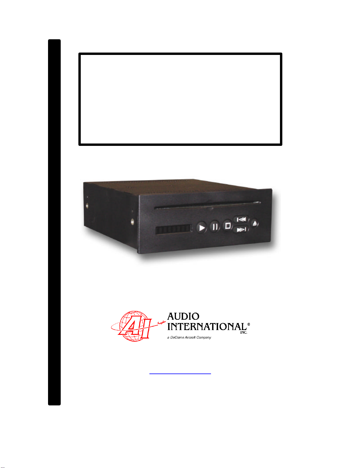
Audio International, Inc. DVD-9101-201-x Installation & Operation Manual
Document # 540339, Rev IR, 11/2006 Page 2of 27
Table of Contents
Section
Description Page
1.0 General Information. . . . . . . . . . . . . . . . . . . . . . . . . . . . . . . . 3
1.1 Introduction . . . . . . . . . . . . . . . . . . . . . . . . . . . . . . . . . . . . . . . 3
1.2 Purpose of the Equipment . . . . . . . . . . . . . . . . . . . . . . . . . . . . 3
1.3 Operational Features . . . . . . . . . . . . . . . . . . . . . . . . . . . . . . . . 4
1.4 Optional Equipment . . . . . . . . . . . . . . . . . . . . . . . . . . . . . . . . . 4
2.0 Application. . . . . . . . . . . . . . . . . . . . . . . . . . . . . . . . . . . . . . . . 5
2.1 Display. . . . . . . . . . . . . . . . . . . . . . . . . . . . . . . . . . . . . . . . . . . 5
2.2 Operating Parameters. . . . . . . . . . . . . . . . . . . . . . . . . . . . . . . . 5
2.3 Media and Format Capabilities. . . . . . . . . . . . . . . . . . . . . . . . . 5
2.4 Typical System Block Diagram . . . . . . . . . . . . . . . . . . . . . . . . 6
3.0 Installation. . . . . . . . . . . . . . . . . . . . . . . . . . . . . . . . . . . . . . . . 7
3.1 Preparation. . . . . . . . . . . . . . . . . . . . . . . . . . . . . . . . . . . . . . . . 7
3.2 Unpacking and Inspection. . . . . . . . . . . . . . . . . . . . . . . . . . . . . 7
3.3 Cautions &Warnings. . . . . . . . . . . . . . . . . . . . . . . . . . . . . . . . 8
3.4 Wiring Requirements. . . . . . . . . . . . . . . . . . . . . . . . . . . . . . . . .
9
3.5 Physical Characteristics. . . . . . . . . . . . . . . . . . . . . . . . . . . . . . 10
3.6 Clearance and Separation Requirements. . . . . . . . . . . . . . . . .
10
3.7 Electrical Characteristics. . . . . . . . . . . . . . . . . . . . . . . . . . . . . . 11
3.8 Mating Connector Information. . . . . . . . . . . . . . . . . . . . . . . . . . 11
3.9 Pinout Assignments and Descriptions. . . . . . . . . . . . . . . . . . . .
12
3.10
Post Installation Test. . . . . . . . . . . . . . . . . . . . . . .. . . . . . . . . . 13
4.0 Operation. . . . . . . . . . . . . . . . . . . . . . . . . . . . . . . . . . . . . . . . . 15
4.1 Front Panel Controls. . . . . . . . . . . . . . . . . . . . . . . . . . . . . . . . . 15
4.2 Front Panel Control Functions. . . . . . . . . . . . . . . . . . . . . . . . . 16
4.3 Other Supported RS-485 and IR Commands. . . . . . . . . . . . . . 20
5.0 Instructions for Continued Airworthiness. . . . . . . . . . . . . . 24
5.1 Cleaning Method. . . . . . . . . . . . . . . . . . . . . . . . . . . . . . . . . . . . 24
5.2 General Troubleshooting Procedures. . . . . . . . . . . . . . . . . . . 24
5.3 Troubleshooting Chart. . . . . . . . . . . . . . . . . . . . . . . . . . . . . . . . 25
5.4 Airworthiness Limitations. . . . . . . . . . . . . . . . . . . . . . . . . . . . . . 25
6.0 Specifications. . . . . . . . . . . . . . . . . . . . . . . . . . . . . . . . . . . . . 26
7.0 Reference Drawings. . . . . . . . . . . . . . . . . . . . . . . . . . . . . . . . 26