Audio international DVD-021-0x-x User manual

7300 Industry Drive, North Little Rock, AR 72117
Phone: 501-955-2929 Fax: 501-955-2988
www.audiointl.com
Installation & Operation
Manual
DVD-021-0x-x
Digital Video Disc Player
Document # 540125

Audio International, Inc. DVD-021-0x-x Installation & Operation Manual
Document # 540125, Rev B, 12/2000 Page 1 of 31
Document Revision History
Rev. Level Date Description
IR 11/1998 Initial Release
A 8/2000 ECN #5260
B 12/2000 Added Maintenance Information, Section I, 7.9
Reference Documents
Document # Description
522187 Rev A DVD-021-0x-x Outline Drawing
522187 Rev IR2 DVD-021-0x-x Outline Drawing
Service Bulletin List
Service
Bulletin # Subject Manual
Revision Revision
Date
Table of Illustrations
PROPRIETARY INFORMATION NOTICE: Despite any other copyright notice, this document and
information disclosed herein contains confidential, proprietary designs owned by Audio
International, Inc. Neither this document nor the data contained herein shall be reproduced, used,
or disclosed to anyone without the written authorization of Audio International, Inc.
Section # Illustration # Description Page #
I 5.0 Technical Specifications 5
I 6.2 Typical Application 5-6
II 6.1 Electrical Specifications 10
II 6.4 Mating Connector Information 11
II 6.5 Pinout Assignment and Descriptions 12
II 8.2 Troubleshooting Chart 13
II 9.0 Reference Drawings 14-15
III 1.0 Front Panel 16
III 4.0 Infrared Remote Control 18
III 4.2 Language Abbreviation Chart 24-25

Audio International, Inc. DVD-021-0x-x Installation & Operation Manual
Document # 540125, Rev B, 12/2000 Page 2 of 31
Table of Contents
Section Description Page
I General Information……………………………………………… 4
1.0 Introduction…………………………………………………………. 4
2.0 Purpose of the Equipment………………………………………… 4
3.0 Operational Features……………………………………………… 4
4.0 Optional Equipment……………………………………………….. 5
5.0 Technical Specifications………………………………………….. 5
6.0 Application………………………………………………………….. 5
7.0 Video/Audio Disc and Unit Care ………………………………… 6
II INSTALLATION…………………………………………………… 7
1.0 Prior to Installation…………………………………………………. 7
2.0 Unpacking and Inspection………………………………………… 7
3.0
Cautions &Warnings……………………………………………… 8
4.0 Wiring Requirements……………………………………………… 9
5.0 Physical Characteristics…………………………………………... 10
6.0 Electrical Characteristics…………………………………………. 10
7.0 Post-Installation Test……………………………………………… 12
8.0 Troubleshooting Guide……………………………………………. 12
9.0 Reference Drawings………………………………………………. 14
III OPERATION……………………………………………………….. 16
1.0 General Information……………………………………………….. 16
2.0 Front Panel Controls………………….…………………………… 17
3.0 Basic Playback…………………………………………………….. 17
4.0 Infrared Remote Control…………………………………………... 18

Audio International, Inc. DVD-021-0x-x Installation & Operation Manual
Document # 540125, Rev B, 12/2000 Page 3 of 31
DVD-021-0x-x
Digital Video Disc Player

Audio International, Inc. DVD-021-0x-x Installation & Operation Manual
Document # 540125, Rev B, 12/2000 Page 4 of 31
SECTION I –GENERAL INFORMATION
1.0 Introduction
This manual contains information for the proper installation and operation of
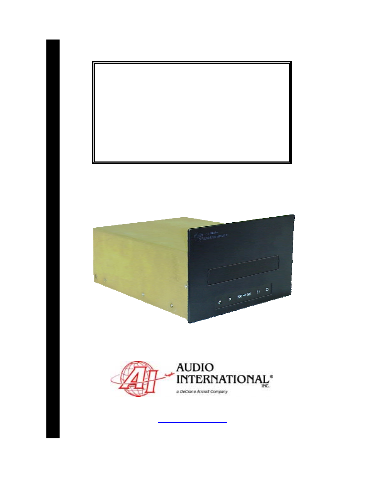
Audio International’s (AI) Digital Video Disc Player,
Model # DVD-021-0x-x. The “-0x”in the model number designates the specific
configuration of the unit. The “-x”in the model number designates the type of
connector utilized in installation. Also included are mechanical and electrical
characteristics of the unit.
2.0 Purpose of the Equipment
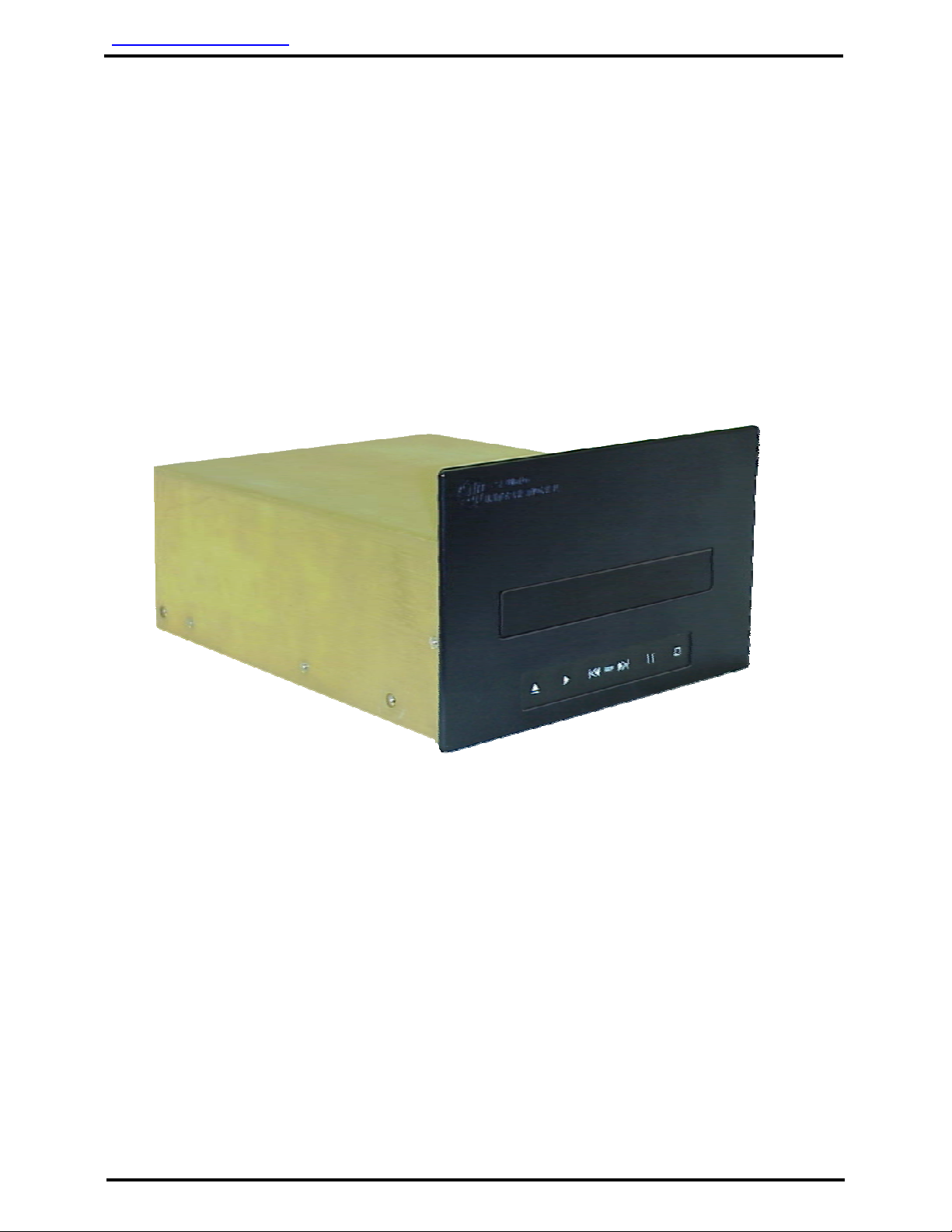
The DVD-021-0x-x is a high-quality videodisc player specifically designed to
meet the special requirements of aircraft use. This videodisc player represents a
new digital medium with the capacity to incorporate an entire feature film –up to
133 minutes of full-motion video per side on a 5" DVD compact disc. Also, the
DVD unit plays standard 5" audio CD’s.
The DVD-021-0x-x can be mounted in a cabinet or bulkhead. A unique strapping
feature allows up to four (4) similar devices to be used in the same system at the
same time while maintaining independent control.
3.0 Operational Features
Key features of the DVD-021-0x-x:
q
Operates directly from +28 VDC
q
Front panel controls
q
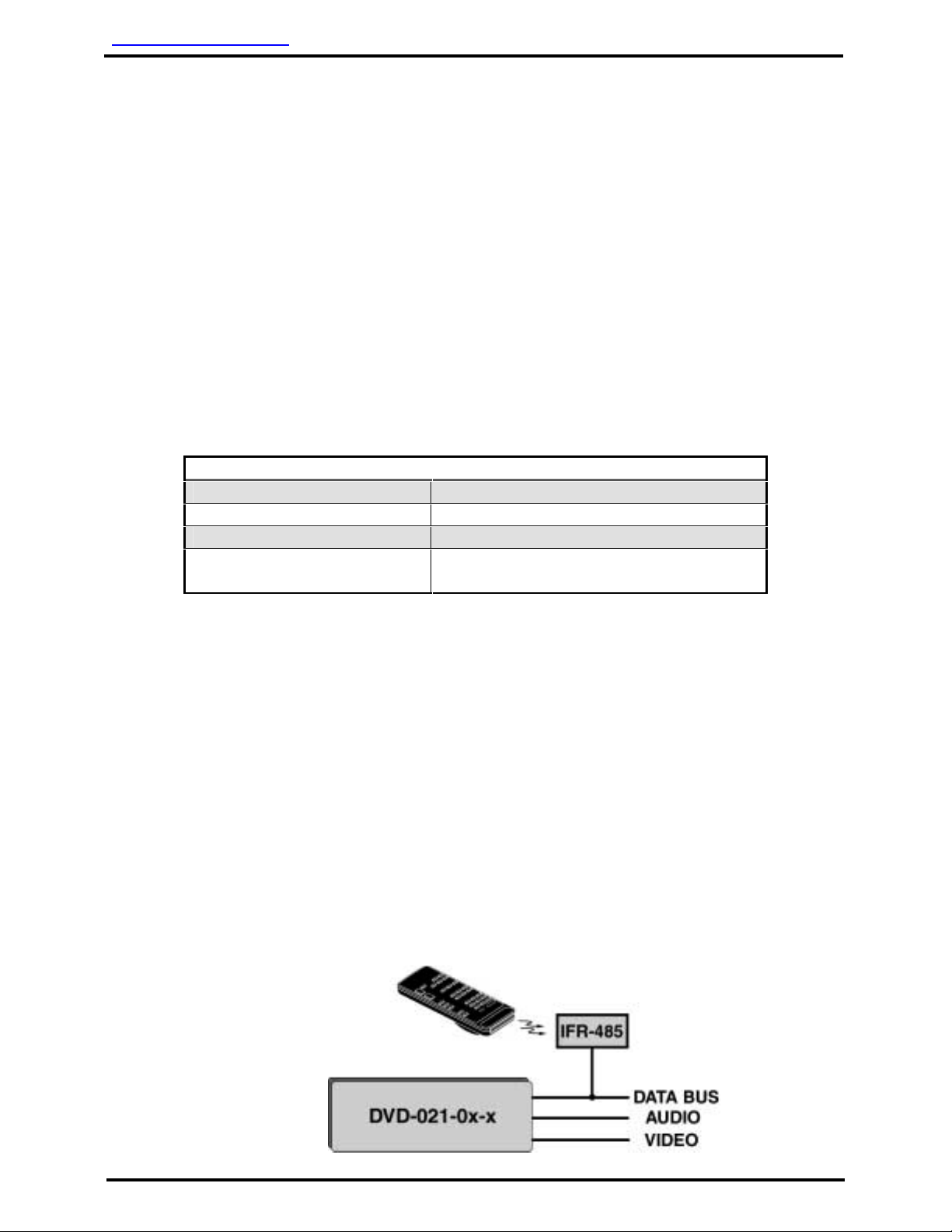
Optional infrared remote controllable
q
High fidelity, digital stereo sound
q
Audio output level +1 to +3VRMS into 330-ohms, internally
adjustable
q
Video output level +1V (p-p) into 75-ohms
q
Full range (4 Hz to 20 kHz) frequency response
q
Eight (8) language and 32 subtitle options (dependent upon user-
supplied disc capabilities)
q
Frame-by-frame video advance and reverse
q
Choice of camera viewing angles (dependent upon ser-supplied
disc capabilities)
q
Favorite segment programming
q
Video disc sizes of 8 cm or 12 cm (single or double-sided)
q
Audio CD disc sizes of 8 cm or 12 cm
q
Standard plating options for front bezel
q
No cooling requirements
q
AI proprietary RS-485 data bus compatible
q
Compact, lightweight package

Audio International, Inc. DVD-021-0x-x Installation & Operation Manual
Document # 540125, Rev B, 12/2000 Page 5 of 31
4.0 Optional Equipment
The DVD-021-0x-x can be optionally controlled by infrared remote or AI’s touch
screen panel. Digital codes allow the unit to interface with an infrared handheld
remote via an infrared receiver, IFR-9A or IFR-485. Multiple units can be
controlled independently using available programming pins. Playback options
with remote or touch screen include visual search, pause, play, stop, fast-
forward, and rewind.
The optional cover bezel may be customized to match the interior style of any
aircraft. This option includes plating or painting to match aircraft décor.
Contact your AI representative for details
5.0 Technical Specifications
Physical Specifications
Housing Aluminum
Weight 4.48 lbs / 2.03 kg
Dimensions
(l x w x h) 10.01" x 7.38" x 4.6"
25.43 cm x 18.75 cm x 11.68 cm
6.0 Application
6.1 Introduction
Two (2) specific DVD-021-0x-x model configurations are available.
½ The DVD-021-01-x plays Region 1 (NTSC color system) formatted
DVD discs.
½ The DVD-021-03-x plays Region 3 (Multi-Regional, both NTSC and
PAL color system) formatted DVD discs.
6.2 Typical Application
6.2.1 This system is fully compatible with Audio International’s proprietary
RS-485 digital data bus system. It can be configured for IR remote
control utilizing AI’s remote control unit AI-RC1-17xxxx and
IFR-485.

Audio International, Inc. DVD-021-0x-x Installation & Operation Manual
Document # 540125, Rev B, 12/2000 Page 6 of 31
6.2.2 The unit can also be configured for IR remote control utilizing AI’s
remote control unit AI-RC1-17xxxx and IFR-9A. This following
configuration utilizes a +5 VDC digital logic level for activation of
infrared commands.
6.2.3 The unit can also be configured for Touch Screen or remote panel
control (i.e. entertainment control panels). The panels are on AI’s
proprietary RS-485 digital data bus system and configured to
control the operational features of the DVD-021-0x-x.
7.0 Video/Audio Disc and Unit Care
7.1 When playing a disc for the first time, check that there are no burrs stuck
in the center hole of the disc.
7.2 DO NOT touch the playback side of the disc.
7.3 DO NOT apply tape to either side of the disc.
7.4 DO NOT store discs in hot locations or in areas exposed to direct sunlight.
7.5 DO NOT store in damp moist areas.
7.6 DO NOT stack loose discs or prop them against anything. Remove discs
from the player and return to their cases after each use.

Audio International, Inc. DVD-021-0x-x Installation & Operation Manual
Document # 540125, Rev B, 12/2000 Page 7 of 31
7.7 DO NOT clean with solvents or other chemical. To clean dirty discs, wipe
gently with a soft, lint-free cloth. Start from the center of the disc and
move outward in a circular motion. Dust or fingerprints on the disc may
cause sound or picture difficulties.
7.8 DO NOT use liquid or aerosol cleaners on the DVD unit. When cleaning
heavy dirt from the unit, soak a soft cloth in a weak detergent solution.
Wring out excess liquid and gently wipe the unit. Dry the unit thoroughly
with a soft cloth.
7.9 NO scheduled maintenance is required to ensure airworthiness.
SECTION II - INSTALLATION
1.0 Prior to Installation
1.1 During the design and layout of the aircraft cabin, careful consideration of
the location of this and all other audio/visual modules is necessary. Some
of the items to be considered include:
• Space
• Available power supply
• Environmental conditions (temperature, humidity, etc.)
• Length of cable runs
• Location of other aircraft systems (oxygen delivery)
1.2 The DVD-021-0x-x shall be installed to conform to the standards
designated by the customer, installing agency, and existing conditions as
to the unit location and type of installation.
1.3 Mounting screws are required to secure the unit. Long low-level audio
runs may introduce noise into the audio signal. Refer to Section 6.0 for
mounting hole diameters and configurations.
1.4 The DVD-021-0x-x shall not be mounted on its side, at an angle or in an
inclined position.
2.0 Unpacking and Inspection
2.1 Carefully open the packaging and remove the DVD-021-0x-x. Verify that
all components have been included in the package per the packing list.
Inspect the unit for shipping damage.

Audio International, Inc. DVD-021-0x-x Installation & Operation Manual
Document # 540125, Rev B, 12/2000 Page 8 of 31
2.2 If damage has occurred during shipping, a claim should be filed with Audio
International WITHIN 24 hours and a Return Request Authorization
Number shall be obtained from AI. Refer to the front cover of this manual
for address and telephone number of Audio International, Inc. Repackage
the unit in its original packaging materials and return it to AI following
instructions given by the AI representative. If no return is necessary,
retain the packing list and the packing materials for storage.
3.0 Cautions & Warnings
3.1 It is important to do a pin-to-pin power and ground check on all
connectors. Ensure that power and ground are applied only where
specified. Damage to the unit may result if power or ground is applied to
the wrong points.
3.2 DO NOT connect or disconnect the unit while power is applied.
3.3 DO NOT remove any factory-installed screws. Damage to the unit may
result and void any warranties.
3.4 DO NOT drop the unit or subject it to strong shock. The unit contains
glass parts that may break or crack.
3.5 DO NOT place foreign objects into openings. Contact with foreign objects
may result in dangerous voltage or electric shock.
3.6 DO NOT place near strong magnetic fields, radiators or other heat
sources.
3.7 DO NOT use this unit other than for its intended purpose. Doing so might
lead to electric shock or injury.
3.8 DO NOT use near water, moisture, or volatile sprays. Do not use any type
of solvent when cleaning (surface damage may occur).
3.9 DO NOT look directly into the laser beam through the disc tray opening.
Eyesight may be damaged.
3.9 DO NOT place fingers in disc tray when the tray is moving. Tray may
close on fingers causing injury.
3.10 DO NOT move the unit during playback. Damage to the disc may result.

Audio International, Inc. DVD-021-0x-x Installation & Operation Manual
Document # 540125, Rev B, 12/2000 Page 9 of 31
3.11 DO NOT expose to sun or bright light. Damage to the sensor will result.
3.12 ESD (Electro Static Discharge) guidelines shall be followed.
4.0 Wiring Requirements
4.1 Introduction
The installing agency shall supply and fabricate all external cables. The
length and routing of external cables should be carefully studied and
planned before attempting installation of the equipment. Allow adequate
space for installation of cable and connectors. Avoid sharp bends and
placing cables near aircraft control cables. Maintain a minimum clearance
of three (3) inches from any control cable. If wiring is run parallel to
combustible fluid or oxygen lines, maintain a separation of six (6) inches
between the lines.
4.2 Power Wires
All power and ground wires shall be 22 AWG, MINIMUM. Power ground
wires shall be grounded within 12 inches of the unit. All wires shall be in
accordance with the standard military specification of MIL-W-22759 or
equivalent. Twisted, shielded cable shall be in accordance with the
standard military specification of MIL-DTL-27500 or equivalent. Protect
power wires with circuit breakers or fuses located close to the electrical
power source bus.
4.3 Video Lines
All video line connections require shielded coaxial cable with the shield
properly grounded at the source. RG-179 cable or equivalent is
recommended.

Audio International, Inc. DVD-021-0x-x Installation & Operation Manual
Document # 540125, Rev B, 12/2000 Page 10 of 31
4.4 AI’s Proprietary RS-485 Data Bus
4.4.1 The DVD-021-0x-x is designed to interface with other Audio
International equipment via AI’s proprietary RS-485 serial data bus.
The data bus shall be implemented using a twisted shielded pair
cable in accordance with the standard military specification of
MIL-DTL-27500 or equivalent. The wire size for the conductors in
this cable shall be 22 AWG, MINIMUM. The shield shall be
connected everywhere a shield pin is provided. Shield terminations
shall be made as close to the connector pin as possible.
4.4.2 All modules on AI’s proprietary RS-485 data bus shall be connected
in a ‘daisy-chain’configuration. AI’s proprietary RS-485 data bus
specification is available upon request.
5.0 Physical Characteristics
5.1 Refer to Section I, Unit 5.0 for unit dimensions.
5.2 Refer to Section II, Unit 9.0 for attachment points.
5.3 When mounting the unit, allow sufficient space for mating connectors.
5.4 Allow a minimum of 1" air space around the unit to allow for proper air
circulation to prevent the build-up of internal heat.
6.0 Electrical Characteristics
6.1 Electrical Specifications:
Electrical Power 750 mA at +28 VDC
Operating Voltage Range +18 VDC to +32 VDC
Data Bus Type AI Proprietary RS-485
Audio Frequency Response 4 Hz to 20 kHz
Audio Output 1 V to 3 VRMS into 330
(factory preset at 2 VRMS)
Audio S/N >96dB (NOMINAL)
Video Output 1V (p-SLQWR
Vertical Resolution 525 Lines
Horizontal Line Resolution 720 Pixels / Horizontal Line
Video Input / Output Format
DVD-021-01-x Region 1
(NTSC only)
DVD-021-03-x
Multi-Regional
(NTSC & PAL)
Infrared Signal Input +5V digital logic level

Audio International, Inc. DVD-021-0x-x Installation & Operation Manual
Document # 540125, Rev B, 12/2000 Page 11 of 31
6.2 The DVD-021-0x-x utilizes one (1) 15-pin connector for electrical
connections. This connector provides power, left/right audio output, data
bus control, infrared input, and four (4) infrared strapping pins for alternate
configuration of infrared digital command codes.
6.3 Standard configuration requires no infrared strap pins to be connected.
Each different type of AI source equipment can be configured to accept
one of four (4) different sets of infrared codes. To change the code
settings, connect one (1) of the strap pins to the strap common (never
connect more than one strap pin to the strap common). Three (3) strap
pins are available to allow the infrared codes to be configured.
6.4 The video output connector (BNC1) allows for proper video output to the
video distribution system.
6.5 The infrared input provides a ground reference connection (-). For
optimum infrared signal transmission, this ground reference connection
should connect along with the chassis ground reference connection (pin 2)
to the same ground termination location as that of the IFR-9A or IFR-485
module being utilized. If this is not possible, then the infrared ground
reference connection for the DVD-021-0x-x should be made within 12" of
the unit.
6.6 Mating Connector Information
Model # Mating Connector
DVD-021-0x-1 RD15F10JVL0
DVD-021-0x-2 DAMA-15S
D20418-2 Female Screwlock
BNC1 Video Input AMPHENOL 31-70018 or equivalent

Audio International, Inc. DVD-021-0x-x Installation & Operation Manual
Document # 540125, Rev B, 12/2000 Page 12 of 31
6.7 Pinout Assignment and Descriptions
Pin Configuration
Pin # Description
1 + 28 VDC
2 Ground
3 R+ Audio Output
4 R- Audio Output
5 L+ Audio Output
6 L- Audio Output
7 Data Bus (A)
8 Data Bus (B)
Data Shield to Pin 2
9 Infrared Input +
10 Infrared Input -
11 IR Strap 2
12 IR Strap 3
13 IR Strap 4
14 IR Strap Common
15 Reserved
7.0 Post-Installation Test
7.1 Verify +28 VDC power has been connected to the unit. The audio signal
output of the unit is generally connected to cabin speaker systems in
addition to headphone locations. Verify all connections before supplying
power to the unit.
7.2 Load the DVD with DVD disc. Use the DVD-021-0x-x front panel controls
or the handheld remote control unit to select PLAY. Verify that a picture
can be viewed on the appropriate monitor and that the audio can be heard
through the speaker/headphone system.
8.0 Troubleshooting Guide
8.1 General Troubleshooting Procedures
Many problems can be isolated with the following general techniques:
• To verify power to the unit, recheck +28 VDC power is applied to the
proper pins on the unit. Use a voltmeter to verify correct level.
• Reset by removing power from the unit for at least one minute and
reapply power. Verify the problem still exists.
• Recheck all connections to the unit for security. Check all harness
runs for possible pinching. Recheck all pinouts for application
accuracy.
• To check data bus integrity, utilizing a voltmeter, “O-scope”or other
voltage instrument, verify proper input voltage on the data bus pins.

Audio International, Inc. DVD-021-0x-x Installation & Operation Manual
Document # 540125, Rev B, 12/2000 Page 13 of 31
8.2 Troubleshooting Chart
Problem Possible Cause Solution
No sound / No picture ½ Unit is improperly
installed
½ No disc in source
unit.
½ Audio system not
powered or active
• Verify +28 VDC power and video
input is present
• Insert DVD in source unit
• Verify audio system is in active
mode
Playback not
functioning ½ Disc not in the
disc tray
½ Disc upside down
or not aligned in
guide
½ Incompatible disc
in tray
½ Dirty Disc
½ Parental lock
activated
½ Menu on the
monitor
• Insert a disc in the tray
• Reposition disc
• Replace disc with compatible one
• Clean the disc
• Change or cancel parental lock
feature
• Exit the current menu
No power ½ Circuit breaker
has opened
• Reset circuit breaker
Poor video quality ½ Poor tape quality • Replace video cassette
Buttons not operating ½ Moisture may
have condensed
inside unit.
• Allow unit to warm to room
temperature and moisture has
evaporated
DVD disc cannot be
loaded ½ Foreign object in
disc slot
• Remove foreign object

Audio International, Inc. DVD-021-0x-x Installation & Operation Manual
Document # 540125, Rev B, 12/2000 Page 14 of 31
9.0 Reference Drawings
The following diagrams show the unit dimensions, mounting locations, and
connector locations for the DVD-021-0x-x.

Audio International, Inc. DVD-021-0x-x Installation & Operation Manual
Document # 540125, Rev B, 12/2000 Page 15 of 31

Audio International, Inc. DVD-021-0x-x Installation & Operation Manual
Document # 540125, Rev B, 12/2000 Page 16 of 31
SECTION III –OPERATION
1.0 General Information
1.1 The DVD-021-0x-x can be operated via front panel ‘buttons’or optionally
controlled by infrared remote or AI’s touch screen panel. Digital codes
allow the unit to interface with an infrared handheld remote via an infrared
receiver, IFR-9A or IFR-485. Multiple units can be controlled
independently using available programming pins.
1.2 Playback options with front ‘button’control, remote or touch screen include
play, skip, pause and stop.
1.3 Before setup or playing a disc, ensure that aircraft power is applied to the
player. There are no non/off controls on the unit.
1.4 Activate monitors and speakers from the appropriate control panels.
Audio will be supplied through headphones and/or speakers per system
design.
1.5 If power is interrupted (>200 msec) or power drops below +18 VDC while
a disc is playing, the player will shut down. If a DVD disc is in the player,
the unit will begin playback from the beginning of the disc automatically. If
an audio CD is in the player, the PLAY button must be pressed on the
front panel or on the infrared remote control before the CD audio can be
heard.
ILLUSTRATION OF DVD-021-0x-x FRONT PANEL

Audio International, Inc. DVD-021-0x-x Installation & Operation Manual
Document # 540125, Rev B, 12/2000 Page 17 of 31
2.0 Front Panel Controls
The names and functions of the DVD-021-0x-x are as follows:
Open / Close button –Press to eject a disc from the disc tray or to load a
disc onto the disc tray.
Play button –Press to start playback of a DVD disc or audio CD.
Skip (backward) button –Press to skip to a previous track.
Skip (forward) button –Press to advance to the next track.
Pause button - To pause a disc or CD playback.
Stop button –To stop the disc or CD playback.
3.0 Basic Playback
3.1 To open the disc tray, press the OPEN / CLOSE button. The disc tray will
eject forward.
3.2 To play a DVD or CD disc, place the desired disc on the disc tray with the
playback side down. Since the DVD will accept either an 8 cm or 12 cm
disc, ensure that the disc is placed on the correct guide. Press the
OPEN / CLOSE button. The disc tray closes and playback of the disc will
begin automatically.

Audio International, Inc. DVD-021-0x-x Installation & Operation Manual
Document # 540125, Rev B, 12/2000 Page 18 of 31
4.0 Infrared Remote Control
ILLUSTRATION
OF TYPICAL
DVD-021-0x-x
REMOTE CONTROL
4.1 Remote Control User Special Instructions
4.1.1 In case batteries begin to lose power, all indicators will flash when
any button is pressed.
4.1.2 To replace batteries, remove the battery compartment cover on the
back of the unit. Load four (4) AAA size Alkaline Manganese
batteries ensuring the positive (+) and negative (-) terminals on the
battery ends match the markings inside the remote control unit.
Service life of the batteries is approximately six (6) months
depending on the frequency of use.
4.1.3 Program codes are not lost when batteries are removed for
replacement. However, codes may be lost within an hour if power
is not restored to the remote control (CAUTION: FACTORY
CODES ARE NOT LOST IF BATTERIES ARE REPLACED
WITHIN THE ONE (1) HOUR TIME FRAME. IF ONLY ONE (1)
BATTERY IS REMOVED, THEN THE ONE (1) HOUR TIME
FRAME STILL APPLIES.) To avoid corrosion, replace dead
batteries immediately. Never mix old batteries with new ones. The
remote control transmitter does not have a power switch. If no
function key is pressed within a short interval, power goes ‘OFF’
automatically to avoid wasting the battery.

Audio International, Inc. DVD-021-0x-x Installation & Operation Manual
Document # 540125, Rev B, 12/2000 Page 19 of 31
4.2 Remote Operation
4.2.1 Basic Playback - Playing Back a Disc
4.2.1.1 To start playback from a menu screen, press one of the
UP, DOWN, LEFT or RIGHT arrow buttons ( )
on the Menu Selection keypad or the number buttons or
the numerical keypad to select the desired title. Press the
ENTER button. The DVD video player will start playback
from the selected title.
4.2.1.2 To pause playback (still mode), press during
playback. To resume normal playback, press the button a
second time.
4.2.1.3 To stop playback, press . The DVD will return to chapter
1 or track 1 of the disc.
4.2.1.4 To remove the disc, press the OPEN / CLOSE button on
the front panel. Remove the disc after the tray opens
completely. Be sure to press the button a second time to
close the tray after the disc has been removed.
4.2.1.5 Discs may be played x2, x8, or x30 the normal speed
although sound and subtitles are not included in the
playback of DVD discs. However, when an audio CD is
played back using fast forward or fast reverse, sound is
audible.
4.2.1.6 To play back a disc at x2 the normal speed, during normal
playback, press (fast reverse) or (fast forward).
The playback becomes x2 the normal speed. Each time
one of the buttons is pressed, the playback speed
changes. Repeat preceding steps to play back disc at x8
or x30 the normal speed. Press (play) to resume normal
playback.
4.2.1.7 To advance a DVD frame by frame, press during
still mode. Each time the button is pressed, the picture
advances one (1) frame. To resume normal playback,
press .
This manual suits for next models
2
Table of contents
Other Audio international Media Player manuals