Audio Precision B Series User manual

B Series
Installation Instructions,
Specifications and
Getting Started Guide
APx511
HEARING INSTRUMENT ANALYZER


APx511
B Series hearing instrument analyzer
Installation Instructions,
Specifications, and Getting Started Guide
B Series APx511
December, 2018

Copyright © 2011–2018 Audio Precision, Inc.
All rights reserved.
Printed in the United States of America.
No part of this manual may be reproduced or transmitted
in any form or by any means, electronic or mechanical, in-
cluding photocopying, recording, or by any information
storage and retrieval system, without permission in writing
from the publisher.
Audio Precision, AP, and APx are trademarks of Audio
Precision, Inc. Windows™ is a trademark of Microsoft Cor-
poration. Dolby and the double-D symbol are trademarks
of Dolby Laboratories, Inc. DTS is a trademark of DTS, Inc.
pn 8211.0363 rev 000 XVIII1121125033
Audio Precision
5750 SW Arctic Drive
Beaverton, Oregon 97005
503-627-0832
800-231-7350
ap.com

Documentation and Support
This booklet contains safety information, installation instructions and full specifications
for the Audio Precision APx511 hearing instrument analyzer.
A Getting Started chapter shows you basic interconnection diagrams and an introduction
to controlling the APx511 with APx500, using our APx Hearing Instrument Analyzer soft-
ware, and integrating the Hearing Instrument Test API with your automation software.
ap.com
Visit the Audio Precision Web site at ap.com for APx support information. You can down-
load the APx511 Hearing Instrument Audio Analyzer Datasheet, the APx Hearing Instrument
Analyzer Software, and APx500 measurement software.
Other APx resources are available at ap.com/. You can also contact our Technical Support
staff at techs[email protected]m, or by telephoning 503-627-0832 ext. 4, or 800-231-7350 ext. 4
(toll free in the U.S.A.).


APx511 B Series Hearing Instrument Analyzer: Safety i
Safety
Safety Information
Do NOT service or repair this equipment unless properly
qualified. Servicing should be performed only by a quali-
fied technician or an authorized Audio Precision distributor.
Do NOT defeat the safety ground connection. This equip-
ment is designed to operate only with an approved three-
conductor power cord and safety grounding. Loss of the
protective grounding connection can result in electrical
shock hazard from the accessible conductive surfaces of this
equipment.
Do NOT exceed mains voltage ratings. This equipment is
designed to operate only from a 50–60 Hz ac mains power
source at 100–240 Vac nominal voltage. The mains supply
voltage is not to exceed ±10 % of nominal (90–264 Vac).
For continued fire hazard protection, fuses should be
replaced ONLY with the exact value and type indicated on
the rear panel of the instrument and discussed on page 5 of
this booklet.
The International Electrotechnical Commission
(IEC 1010-1) requires that measuring circuit terminals used
for voltage or current measurement be marked to indicate
their Measurement Category. The Measurement Category is
based on the amplitude of transient or impulse voltage that
can be expected from the AC power distribution network.
This product is classified as Measurement Category I,
abbreviated “CAT I”. This product should not be used
within Categories II, III, or IV. The APx511 measurement
terminals are intended to be used for the measurement of
audio signals only.
Do NOT substitute parts or make any modifications with-
out the written approval of Audio Precision. Doing so may

Safety
ii APx511 B Series Hearing Instrument Analyzer: Safety
create safety hazards. Using this product in a manner not
specified by Audio Precision can result in a safety hazard.
This product is for indoor use—Installation Category II,
Measurement Category I, pollution degree 2.
To clean the enclosure of this product, use a soft cloth or
brush to remove accumulated dust. A mild detergent may be
used to remove remaining dirt or stains. Do not use strong
or abrasive cleaners. Wipe all surfaces with a damp cloth.
This unit is supplied with four feet on the bottom surface
and four feet on the right side surface. The unit should only
be operated while resting on the bottom surface feet. The
feet on the right side are provided for convenience and sta-
bility when transporting the unit. DO NOT operate the unit
while it is sitting on the side feet.
Safety Symbols
The following symbols may be marked on the panels or
covers of equipment or modules, and are used in this man-
ual:
WARNING!—This symbol alerts you to a potentially haz-
ardous condition, such as the presence of dangerous volt-
age that could pose a risk of electrical shock. Refer to the
accompanying Warning Label or Tag, and exercise extreme
caution.
ATTENTION!—This symbol alerts you to important oper-
ating considerations or a potential operating condition that
could damage equipment. If you see this marked on equip-
ment, refer to the Operator’s Manual or User’s Manual for
precautionary instructions.
FUNCTIONAL EARTH TERMINAL—A terminal marked
with this symbol is electrically connected to a reference
point of a measuring circuit or output and is intended to be
earthed for any functional purpose other than safety.
PROTECTIVE EARTH TERMINAL—A terminal marked
with this symbol is bonded to conductive parts of the instru-
ment and is intended to be connected to an external protec-
tive earthing system.
Disclaimer
Audio Precision cautions against using their products in a
manner not specified by the manufacturer. To do otherwise
may void any warranties, damage equipment, or pose a
safety risk to personnel.

APx511 B Series Hearing Instrument Analyzer: Sécurité iii
Sécurité
Consignes de sécurité
Ne procédez PAS à l’entretien ou à la réparation de cet
équipement à moins d’être dûment qualifié(e) pour le faire.
L’entretien devrait être effectué uniquement par un tech-
nicien qualifié ou un distributeur Audio Precision agréé.
Ne PAS dérouter le branchement de la mise à la terre de
sécurité. Cet équipement est conçu pour être utilisé unique-
ment avec un cordon d’alimentation approuvé avec connec-
teur à trois conducteurs et mise à la terre de sécurité. La
perte de connexion à la mise à la terre protectrice peut
entraîner un risque de choc électrique à partir des surfaces
conductrices accessibles de cet équipement.
Ne PAS dépasser la tension de réseau nominale. Cet équipe-
ment est conçu pour fonctionner uniquement à partir d’une
source d’alimentation réseau de 50–60 Hz CA, à une ten-
sion nominale de 100–240 V CA. La tension d’alimenta-
tion du réseau ne doit pas dépasser ±10 % de la tension
nominale (90–264 V CA).
Pour obtenir en permanence la protection contre les risques
d’incendie, les fusibles doivent être remplacés UNIQUE-
MENT par des fusibles de même valeur et type, comme
indiqué sur le panneau arrière de l’instrument et précisé à la
page 7 de ce livret.
La International Electrotechnical Commission (la Commis-
sion électrotechnique internationale) (CEI 1010-1) exige
que les bornes des circuits de mesure utilisées pour la
mesure de la tension ou du courant identifient leur catégorie
de mesure. La catégorie de mesure se base sur l’amplitude
de la tension transitoire ou de la tension d’impulsion à
laquelle on peut s’attendre d’un réseau de distribution d’ali-
mentation électrique CA. Ce produit est classé dans la
catégorie de mesure I, selon l’abréviation « CAT I ». Ce
produit ne devrait pas être utilisé dans les catégories II, III

Sécurité
iv APx511 B Series Hearing Instrument Analyzer: Sécurité
ou IV. Ces bornes sont destinées à la mesure des signaux
audio seulement.
Ne PAS remplacer de pièces ou effectuer de modifications
sans l’approbation écrite d’Audio Precision. Si c’est le cas,
il pourrait y avoir des risques pour la sécurité. Utiliser ce
produit d’une manière non précisée par Audio Precision
peut entraîner un risque pour la sécurité.
Ce produit est destiné à une utilisation à l’intérieur-
Catégorie d’installation II, Catégorie de mesure I, degré de
pollution 2.
Pour nettoyer le boîtier de ce produit, utiliser un chiffon
doux ou une brosse douce permettant d’éliminer la saleté
accumulée. Un détergent doux peut être utilisé pour élimi-
ner la saleté ou les taches. Ne pas utiliser de produits net-
toyants forts ou abrasifs. Essuyer toutes les surfaces à l’aide
d’un chiffon humide.
Cette unité est fournie avec quatre pattes sur le dessous et
quatre pattes sur le côté droit. L’unité doit être utilisée
uniquement lorsqu’elle repose sur les pattes du dessous. Les
pattes sur le côté droit sont installées pour plus de commod-
ité et de stabilité lors du transport. NE PAS utiliser l’unité
lorsqu’elle repose sur les pattes du côté
Symboles de sécurité
Les symboles suivants peuvent être présents sur les pan-
neaux ou les couvercles de l’équipement ou des modules, et
sont utilisés dans le présent manuel:
AVERTISSEMENT!—Ce symbole vous informe d’une sit-
uation potentiellement dangereuse, par exemple, la présence
d’une tension dangereuse qui pourrait présenter un risque de
choc électrique. Consultez l’autocollant ou l’étiquette
d’avertissement qui l’accompagne, et faites preuve d’une
grande prudence.
ATTENTION!—Ce symbole vous informe d’importantes
considérations liées au fonctionnement ou d’une condition
d’utilisation potentielle qui pourrait endommager l’équipe-
ment. Si vous voyez ce symbole sur l’équipement, consul-
tez le manuel de l’opérateur ou le manuel de l’utilisateur
pour connaître les instructions préventives.
BORNE DE TERRE FONCTIONNELLE— Les bornes
identifiées à l’aide de ce symbole sont reliées électrique-
ment à un point de référence d’un circuit ou d’une sortie de
mesure et doivent être raccordées à la terre (mise à la terre)
pour toute fonction utilitaire autre que la sécurité.

Sécurité
APx511 B Series Hearing Instrument Analyzer: Sécurité v
BORNE DE TERRE DE PROTECTION—Les bornes iden-
tifiées à l’aide de ce symbole sont liées à des pièces conduc-
trices de l’instrument et elles doivent être raccordées à un
système protecteur de mise à la terre externe.
Avis de non-responsabilité
Audio Precision déconseille fortement l’utilisation de ses
produits d’une manière non spécifiée par le fabricant. Une
telle utilisation pourrait annuler toute garantie, endom-
mager l’équipement ou présenter un risque de sécurité pour
le personnel.

Sécurité
vi APx511 B Series Hearing Instrument Analyzer: Sécurité

APx511 B Series Hearing Instrument Analyzer: Seguridad vii
Seguridad
Información de seguridad
NO proporcione servicio o reparación a este equipo a
menos que esté debidamente calificado. El trabajo de servi-
cio deberá ser efectuado solamente por un técnico califi-
cado o un distribuidor autorizado de Audio Precision.
NO modifique la conexión de seguridad a tierra. Este
equipo está diseñado para operar solamente con una exten-
sión aprobada de tres conductores puestos a tierra de seguri-
dad. La pérdida de conexión de protección a tierra puede
dar como resultado un peligro de descarga eléctrica al tocar
las superficies conductoras accesibles de este equipo.
NO exceder las clasificaciones de la tensión de red eléc-
trica. Este equipo está diseñado para operar solamente de
una fuente de suministro eléctrico de 50–60 Hz de corriente
alterna a una tensión nominal de 100–240 VCA. La fuente
de suministro de voltaje no debe exceder del ±10 % del
nominal (90–264 VCA).
Para protección continua contra riesgo de incendio, los fus-
ibles deberán reemplazarse SOLAMENTE con fusibles de
valor y tipo exactos indicados en el panel posterior del
instrumento y que se explica en la página 11 de este folleto.
International Electrotechnical Commission [La Comisión
Electrotécnica Internacional] (IEC 1010-1) requiere que los
terminales del circuito de medición que se utilizan sola-
mente para medición de voltaje o corriente se marquen para
indicar la categoría de medición. La categoría de medición
se basa en la amplitud del voltaje transitorio o de impulso
que se puede esperar de la red de distribución de voltaje de
CA. Este producto se clasifica como Categoría de Medición
I, abreviado como “CAT I”.

Seguridad
viii APx511 B Series Hearing Instrument Analyzer: Seguridad
Este producto no deberá usarse dentro de las categorías II,
III, o IV. Los terminales de medición de entrada están con-
cebidos para usarse solamente para la medición de señales
de audio.
NO reemplace partes ni haga modificaciones sin la aproba-
ción por escrito de Audio Precision. Hacerlo podría causar
riesgos de seguridad. El uso de este producto en una manera
no especificada por Audio Precision puede resultar en un
riesgo de seguridad.
Este producto es para uso en interiores-Categoría de insta-
lación II, Categoría de medición I, grado de contaminación
2.
Para limpiar la caja de este producto, utilice un trapo o
cepillo suave para remover el polvo acumulado. Se puede
utilizar un detergente neutro para remover la suciedad o
manchas remanentes. No utilice limpiadores fuertes o abra-
sivos. Limpie todas las superficies con un trapo húmedo.
Esta unidad se suministra con cuatro patas en la superficie
inferior y cuatro patas en la superficie del costado derecho.
La unidad solamente debe operarse al estar apoyada en las
patas de la superficie inferior. Las patas en el costado dere-
cho se proporcionan para conveniencia y estabilidad al
transportar la unidad. NO opere la unidad al estar apoyada
sobre las patas laterales.
Símbolos de seguridad
Los siguientes símbolos podrían estar marcados en los pan-
eles o cubiertas del equipo o los módulos, y se utilizan en
este manual:
¡ADVERTENCIA!—Este símbolo le alerta sobre una
condición potencialmente peligrosa, tal como la presencia
de voltaje peligroso que pudiera representar un riesgo de
descarga eléctrica. Consulte la etiqueta de advertencia
adjunta y tenga mucha precaución.
¡ATENCIÓN!—Este símbolo le alerta de consideraciones
operativas importantes o de una condición operativa poten-
cial que pudiera dañar al equipo. Si usted ve este símbolo en
el equipo, consulte el Manual del operador o el Manual del
usuario para instrucciones de precaución.
TERMINAL DE TIERRA FUNCIONAL—Un terminal
marcado con este símbolo está conectado eléctricamente a
un punto de referencia de un circuito de medición o salida y

Seguridad
APx511 B Series Hearing Instrument Analyzer: Seguridad ix
se supone está conectado a tierra (aterrizado) para algún fin
funcional diferente a la seguridad.
TERMINAL DE TIERRA DE PROTECCIÓN—Un termi-
nal marcado con este símbolo está enlazado a partes con-
ductores del instrumento y se supone que está conectado a
un sistema externo de protección a tierra (aterrizada).
Exención de responsabilidad
Audio Precision advierte contra el uso de este producto de
una manera no especificada por el fabricante. El hecho de
no hacerlo de la manera indicada invalidaría las garantías,
causaría daño al equipo, o representaría un riesgo de seguri-
dad para el personal.

Seguridad
x APx511 B Series Hearing Instrument Analyzer: Seguridad

APx511 B Series Hearing Instrument Analyzer: Installation 1
Installation
Software
The APx511 hearing instrument analyzer system uses the
award-winning APx500 measurement software, whether
using the GUI in the foreground, or controlling APx500 in
the background using the API. This is the same software
used in the APx525and APx585 analyzer families.
APx “B Series” analyzers
All analyzers shipped in late December 2018 (or afterward)
have a new embedded processor and enhanced security pro-
visions. These analyzers are designated “B Series” and
carry “B Series” nomenclature. “B Series” APx analyzers
do not require an APx KeyBox (see below), but may require
authorization codes to enable APx500 software or software
options.
The APx KeyBox
If you are using APx500 software version 4.6 or later with
an earlier APx analyzer (non “B Series”), you must attach
an authenticated APx KeyBox to the Software Options con-
nector on the analyzer rear panel.
The APx KeyBox must be programmed with your ana-
lyzer’s serial number at the Audio Precision factory, and
cannot be used with any other APx analyzer. You may
require authorization codes to enable APx500 software or
software options.
Note that without a properly authenticated APx KeyBox
attached, APx500 version 4.6 or later will only run in demo
mode. If you need a KeyBox, locate your analyzer serial
number and go to https://ap.com/get-keybox/ to complete
the order form. The APx KeyBox is provided at no cost,
free of charge.

Installation
2 APx511 B Series Hearing Instrument Analyzer: Installation
Analyzer serial numbers are located on the configuration
label on the analyzer rear panel, and on the calibration label
on the forward edge of the top panel.
PC system requirements
The APx500 measurement software requires a personal
computer (PC) with the following features and capabilities:
• Operating system: Microsoft Windows 10 (64-bit),
Windows 8 (64-bit), or Windows 7 (64-bit).
• A multi-core processor (at least dual-core) running at a
clock speed of at least 2 GHz. Most current processors
from Intel and AMD meet these requirements.
Note: the Intel Atom processor does not meet our
minimum specification.
• At least 2 GB of RAM.
• At least 300 MB of free hard disk space.
• A CD-ROM optical disc drive.
• A USB 2.0 port; two are required for optional switcher
use.
• A color monitor and a video card with at least VGA
capabilities. Video resolution of 1024 x 768 or greater
is recommended.
System performance is sensitive to processor speed; faster
processors will yield faster results.
APx500 is data intensive and it is recommended that other
data-intensive applications not be run concurrently. This
includes Audio Precision’s AP2700, APWIN or ATS.
Installation
To install the measurement software, insert the APx500
application disc into the optical drive on the PC and follow
the instructions in the installation dialog. If you don’t have
the APx500 application disc, you can download APx500
from the Audio Precision Web site at ap.com.
NOTE: You must have local administrator rights
to install APx500 software. Go to User Accounts
in the Windows Control Panel, or check with your
network administrator.
Running the software without instrument hard-
ware attached
NOTE: You must have standard user rights or
administrator rights to operate APx500 software.
Guest users are not supported.
You can launch the APx500 software without instrument
hardware attached. When no hardware is detected, APx500
will present you with the following dialog box:
Select “Demo Mode.” APx500 will run in demo mode,
which allows you to explore the user interface but does not
enable any measurement functions. Input data shown in
Demo Mode is false data, generated for display only.
At first launch, Demo Mode runs simulating attachment to
an APx585. To run Demo Mode simulating anther instru-
ment, select that option from the Instrument Type menu.

Installation
APx511 B Series Hearing Instrument Analyzer: Installation 3
Running the software with instrument hardware
attached
NOTE: You must have standard user rights or
administrator rights to operate APx500 software.
Guest users are not supported.
Connecting the instrument to your PC
Before connecting your APx511 instrument to your PC,
install the APx500 measurement software as described
above. Connecting the instrument prior to software installa-
tion may cause Windows to select an incorrect USB driver
for the instrument.
USB driver selection
The measurement software communicates with the APx511
using a USB 2.0 interconnection. Once the software is suc-
cessfully installed, connect one end of the USB cable to a
USB 2.0 port on the PC, and the other end to the PC
INTERFACE port on the rear of the APx511. We strongly
recommend that you use the USB cable included with your
instrument (AP part number CAB-APSI). We have tested
other USB cables that perform poorly.
Note: Some PCs have optional USB ports on the
front of the PC, or on extension brackets on the
rear. In many cases these convenience ports
have compromised performance due to the extra
cable length within the PC. We recommend using
USB ports directly connected to the PC mother-
board, typically at the rear of the PC.
Connect the APx511 mains power cord to the instrument
and to a source of ac mains power. See Setting up the
hardware below for more information about mains connec-
tions.
Turn the instrument on by rocking the mains power switch
up to ON ( | ). The mains power switch is located in the
power entry module on the rear of the APx511. Windows
will detect the presence of the APx511 on the USB port and
will open the Hardware Update Wizard to search for the
correct software driver. Select “Install the software automat-
ically.” Windows will find the Audio Precision driver soft-
ware installed with APx500 and connect to the APx511.
Launch APx500 by double-clicking on the installed short-
cut. With the APx511 connected, you may be asked to
update the instrument firmware during the first launch of
the measurement software. APx500 will start, and in a short
time you will be presented with the opening screen. Refer to
the APx500 User’s Manual for more information about
making measurements.
The APx500 User’s Manual is available as a PDF
on the APx500 Application Disc and online at
ap.com; a hard-copy version can be ordered from
Audio Precision or your local distributor.
Setting up the hardware
Connecting your instrument to the electrical
mains supply
The APx511 instrument must be connected to a 50–60 Hz
alternating current (ac) electrical mains supply, maximum
voltage 250 Vrms.
The instrument has been configured at the factory for the
expected voltage at its intended destination, as ordered. The
voltage setting and fusing arrangement will normally be
correct unless the instrument has been transported into
another area. The power entry module has a strip of indica-

Installation
4 APx511 B Series Hearing Instrument Analyzer: Installation
tor tape showing its mains voltage setting. This tape must
be removed before use.
You MUST be sure that the APx511 instrument
mains power configuration is correct for the elec-
trical mains power supplied in your area. If you
are not sure, do not plug the instrument into the
mains power. Follow the instructions below to
check or change the instrument mains supply
voltage selection.
The mains power supply is applied to your APx511 instru-
ment through the power entry module located on the rear
panel. Before connecting the power cord, confirm that the
input voltage selection and fusing arrangement in the power
entry module are correct for your mains power supply.
Figure 2. Detail of power entry module on
APx511 instrument rear panel.
The mains power switch is to the left.
Checking the mains supply voltage configura-
tion
The white plastic voltage indicator pin protrudes through
one of the four labeled holes in the module cover to indi-
cate the selected input voltage. Figure 2 shows the pin in the
second position, indicating 120 V. Check to see that the
indicated voltage matches your mains supply voltage. If it
does not, change the mains supply voltage configuration as
described below.
Opening the power entry module
Unplug the power cord from the instrument before chang-
ing fuses or performing any other operations described in
this section.
To open the power entry module, refer to Figure 3 and pro-
ceed as follows:
Figure 3. Power entry module door and fuse block.
• Remove the mains power supply cord from the power
cord connector.
Other manuals for B Series
3
This manual suits for next models
1
Table of contents
Other Audio Precision Measuring Instrument manuals

Audio Precision
Audio Precision AUX-0025 User manual
Audio Precision
Audio Precision B Series User manual
Audio Precision
Audio Precision APx500 Flex User manual
Audio Precision
Audio Precision APx52 series User manual
Audio Precision
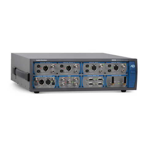
Audio Precision AP 52 B Series User manual
Audio Precision
Audio Precision APx555 User manual
Audio Precision
Audio Precision Lynx Aurora User manual

Audio Precision
Audio Precision B Series User manual
Audio Precision
Audio Precision ATS-1 User manual

Audio Precision
Audio Precision APx500 Flex User manual

