Audio Technica ATW-T94 Owner's manual

ATW-T94
UHF Handheld Microphone /Transmitter
Installation and Operation

2
ATW-T94 UHF Handheld Microphone / Transmitter
Audio-Technica Engineered Sound¨wireless systems
are offered as separate receiver and transmitter units,
rather than in predetermined combinations, for greatest
system flexibility. Operating details for Engineered
Sound receivers and overall system operation are
included with each receiver.
Engineered Sound receivers feature a sophisticated
Tone Lockªtone squelch system that opens only when
an Engineered Sound transmitter is detected, reducing
the possibility of interference. As a result, Engineered
Sound transmitters and receivers must be used
together and should not be used with components
from other Audio-Technica wireless systems, or with
those of other manufacturers.
Please note that in multiple-system applications there
must be a transmitter-receiver pair set to a separate
frequency for each input desired (only one transmitter
at a time for each receiver). Because the wireless
frequencies are on UHF TV frequencies, only certain
wireless frequencies may be useable in a particular
geographic area. Also, only certain of the available
operating frequencies may be used together.
Introduction
Battery Selection and Installation
The transmitter uses two 1.5V AA batteries, not
included. Alkaline type is recommended. Always
replace both batteries.
Make certain the transmitter
power switch is turned Off before replacing
batteries.
Battery Installation
1. While holding the
transmitter body at
the on-off switch,
unscrew the lower body
cover and slide it off to expose
the battery compartment (Fig. A).
Fig. A
Transmitter Setup
Fig. B
Fig. C
Battery Condition Indicator
After the batteries are installed, turn the power on. The
red battery condition indicator LED (Fig. D) should flash
momentarily and the green indicator should come on. If
this does not happen, the batteries are installed incor-
rectly or they are dead. If the yellow or red indicator
stays on, the battery voltage is low and the batteries
should be replaced. If this happens during use, replace
the batteries immediately to ensure continued opera-
tion.
Fig. D
BATT
ON
Green
Red Yellow
2. Observe correct polarity as marked inside the battery
compartment and carefully insert two fresh 1.5V AA
alkaline batteries(Fig. B).
Because there is some
variation in actual battery
dimensions, make centain
the batteries are fully seated
in the battery compartment.
3. Replace the lower body cover (Fig. C).Do not
overtighten.
Transmitter Controls
POWER SWITCH: The Power switch controls the entire
transmitter. There is about a half-second delay after
transmitter turn-on before the receiver's Tone Lock
squelch un-mutes.
Remove the lower body cover to access the following
controls.
PAD SWITCH: The ATW-T94 offers a Pad switch with
0/-6/-12 dB positions which increases the maximum
SPL (sound pressure level) capability of the
microphone. Use the "0" (no pad) position unless very
high SPLs are encountered.
CHANNEL SWITCHES: The left channel selector switch
corresponds to the receiver's left-column channel
display number (tens); the right switch corresponds to
the receiver's right-column channel display number
(units). Always turn the transmitter off when changing
frequencies.
RF POWER / BATTERY-SAVE SWITCH: As supplied, the
switch is set in the "H" (high) position for maximum
range. Switching to the "L" (low) position increases
battery life somewhat by reducing power. (Note:
Effective range may decrease when the switch is set at
the "L" position.)
Fig. E
Transmitter Controls
BATT
ON
RFPOWER
HL
PAD(
dB)
-6
0
-12
CH
Battery
Condition
Indicator
Pad
Switch Channel
Switch
x10
Power
Switch
Channel
Switch
x1
RF Power/
Battery-Save
Switch
Screwdriver
Storage
Serial
Number

3
Turn down the mixer/amplifier level before starting
up the wireless system.
Switch on the receiver. Do
not
switch on the
transmitter yet.
Receiver On-
The Channel Designator Display will light. If any of the
RF LEDs light up at this point, there may be RF
interference in the area. If this occurs, select another
frequency using the front-panel channel selectors.
While holding in the "Set" button, press the "Up" or
"Down" button to access the desired frequency; then
release the Set button to select the channel.
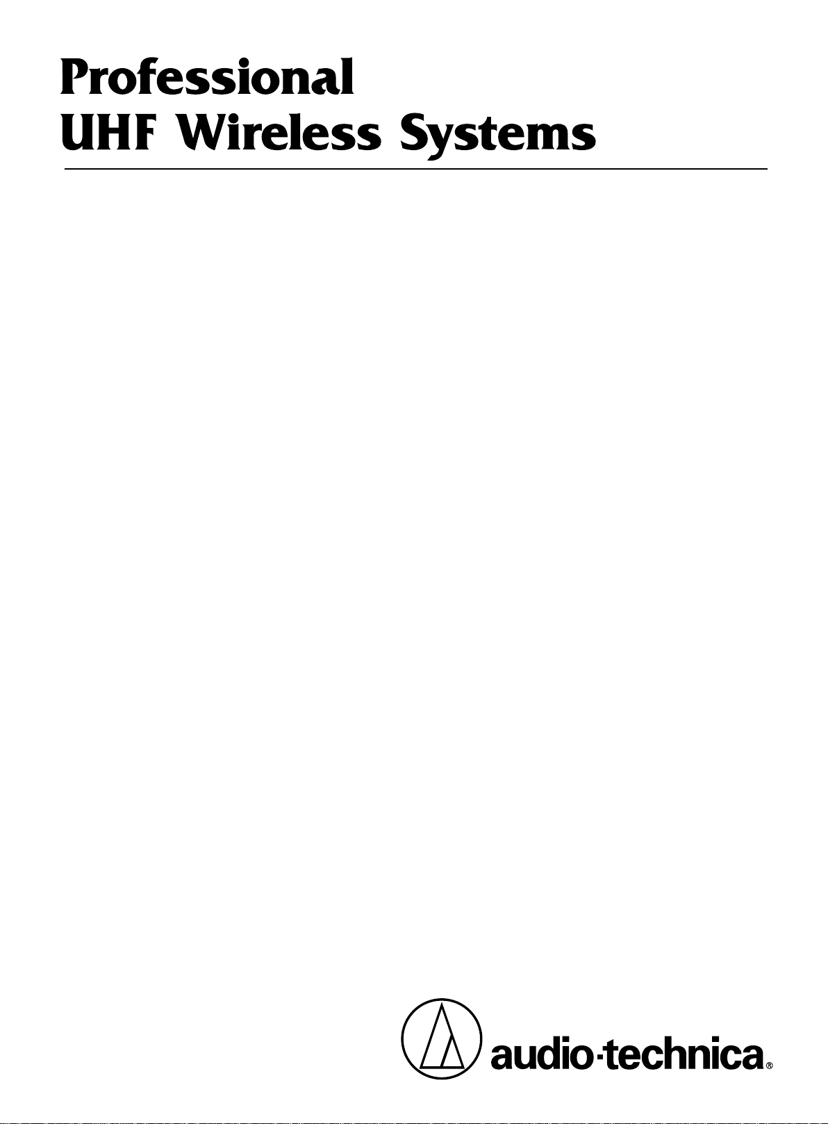
Transmitter On-
Before turning on the transmitter , use the provided
screwdriver to set the transmitter channel selector
switches (Fig. F) to the same numbers as those dis-
played on the receiver. Always turn the transmitter off
when changing frequencies. When the transmitter is
switched on and in normal operation, the receiver's RF
signal level indicators will light up from left to right. For
optimum performance at least four, and preferably five,
of the signal strength indicators should light up when
the transmitter is switched on. One of the Tuner LEDs
(A or B) also will light up when the transmitter is on,
indicating that its signal has been received and the
receiver's Tone Lock squelch circuit has opened.
CH
8
7
6
5
4
3
7
6
5
4
3
System Operation
Fig. F
Setting Levels
Although Engineered Sound receivers require no level
adjustment, correct adjustment of transmitter audio
input and mixer/amplifier input and output levels is
important for optimum system performance.
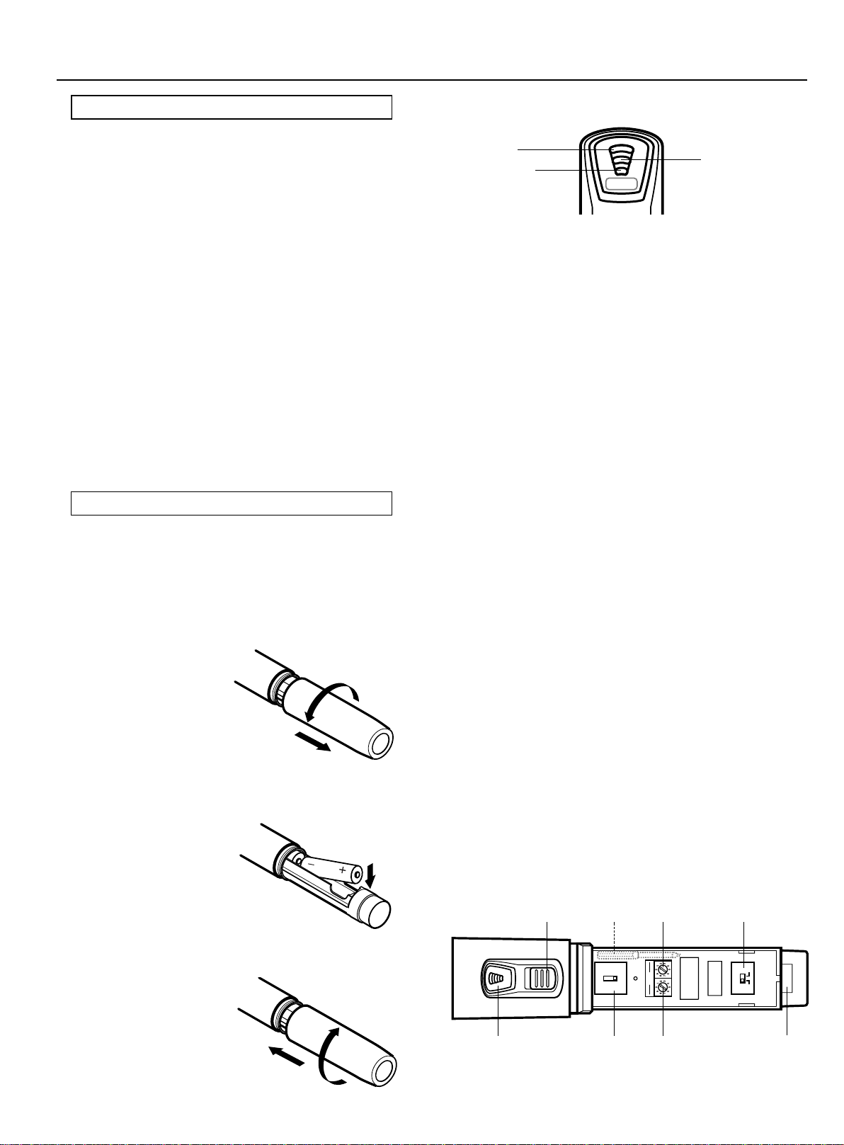
The ATW-T94 handheld transmitter has a 0/-6/-12 dB
audio input Pad switch under the lower body cover. It is
factory pre-set at "0" for maximum audio input gain. If
four or five AF Level LEDs on the receiver illuminate
with maximum audio input, first try using the -6 dB
position. Extremely high audio input may require use
of the -12 dB setting. (Use the Pad switch only when
needed; excessive use will affect the maximum signal-
to-noise ratio of the system.)
1. Turn the transmitter on and power up the system.
2. Turn down the mixer' s input trim control (if provided)
on the selected channel; make an initial adjustment of
the mixer channel and output level controls that will
allow audio through the system.
3. While speaking/singing into the microphone at
typically-loud levels, adjust the mixer's input trim
control so the highest sound pressure level going into
the microphone causes no input overload in the mixer,
and yet permits the mixer' s level controls to operate in
their "normal" range (not set too high or too low).
RF Interference
Please note that wireless frequencies are shared with
other radio services. According to Federal
Communications Commission regulations, "Wireless
microphone operations are unprotected from interfer-
ence from other licensed operations in the band. If any
interference is received by any Government or non-
Government operation, the wireless microphone must
cease operation..."
If you need assistance with operation or frequency
selection, please contact your dealer.
Tips To Obtain The Best Results
- Use only fresh alkaline batteries. Do not use
"general purpose" (carbon-zinc) batteries.
- The transmitter and the receiver should be as
close together as conveniently possible, but
no closer together than three feet. Maintain
line-of-sight between them whenever
possible.
- Each transmitter/receiver pair must be set to
the same channel number.
- A single receiver cannot receive signals from
two transmitters at the same time.
- You need to change channels 1) when a
strong interference signal is received,
2) when the channel breaks down, or
3) during multiple-system operation
in order to select an interference-free channel.
- Turn the transmitter off when not in use.
Remove the batteries if the transmitter is not
to be used for a period of time.
Specifications
OVERALL SYSTEM
Operating Frequency UHF band, 800.550 to 819.700MHz
Number of Channels 100 total
Frequency Stability ±0.005%, Phase Lock Loop
frequency control
Modulation Mode FM
Normal Deviation ±5 kHz
Tone Squelch Frequency 32.768 kHz
Operating Range 90m typical
Operating Temperature Range 5C degree to 45C degree
Frequency Response 100 Hzto 15 kHz
ATW-T94 HANDHELD TRANSMITTER
RF Power Output 50 mW Max (H: 10 mW;
L: 5 mW, typical)
Spurious Emissions Under federal regulations
Microphone Element A-T Hi-ENERGY
¨dynamic,
unidirectional
Batteries Two 1.5V AA type alkaline,
not included
Current Consumption H: 105 mA; L: 95 mA, typical
Battery Life H: 16 hours; L: 18 hours,
typical (depending on battery
type and use pattern)
Dimensions 53.5 mm dia. x 239.0 mm long
Net Weight (without batteries) 295 grams
Accessory Included AT8456 stand clamp
Transmitter Accessories
AT8114 Foam windscreen for handheld transmitter.
AT8456 Stand clamp for handheld transmitter, 5/8"-27 threads.

Ch. Frequency (MHz) Ch. Frequency (MHz)
00 800.550
01 800.575
02 800.600
03 801.100
04 801.125
05 801.150
06 801.200
07 801.450
08 801.925
09 801.950
10 801.975
11 802.075
12 802.200
13 802.225
14 802.250
15 802.325
16 802.575
17 803.025
18 803.050
19 803.075
20 803.550
21 803.575
22 803.600
23 803.625
24 803.700
50 810.075
51 810.200
52 810.325
53 810.550
54 810.575
55 811.075
56 811.100
57 811.550
58 811.575
59 811.600
60 811.700
61 812.775
62 812.800
63 812.825
64 812.850
65 813.075
66 813.100
67 813.125
68 813.200
69 813.300
70 813.750
71 813.775
72 814.850
73 814.875
74 814.950
25 804.825
26 805.075
27 805.150
28 805.200
29 805.300
30 805.775
31 806.900
32 806.925
33 806.950
34 807.400
35 807.425
36 807.450
37 808.525
38 808.550
39 808.575
40 808.600
41 808.625
42 809.100
43 809.175
44 809.200
45 809.225
46 809.450
47 809.475
48 809.925
49 809.950
75 815.425
76 815.450
77 816.525
78 816.550
79 816.575
80 816.650
81 817.100
82 817.125
83 817.200
84 817.450
85 817.925
86 817.950
87 818.075
88 818.200
89 818.225
90 818.325
91 818.550
92 818.575
93 819.025
94 819.050
95 819.075
96 819.550
97 819.575
98 819.600
99 819.700
Frequency and Channel Designator List
Notice to individuals with implanted cardiac pacemakers or AICD devices :
Any source of RF (radio frequency) energy may interfere with normal functioning of the implanted device. All wireless microphone
have low-power transmitters (less than 0.05 watts output) which are unlikely to cause difficulty, especially if they are at least a few
inches away. Note also that any medical-device disruption will cease when the RF transmitting source is turned off. Please contact
your physician or medical-device provider if you have any questions, or experience any problems with the use of this or any other
RF equipment.
CAUTION! The circuits inside the receiver and transmitter have been precisely adjusted for optimum performance and compliance
with federal regulations. Do not attempt to open the receiver or transmitter. To do so will void the warranty, and may cause improper
operation.
Ch. Frequency (MHz)Ch. Frequency (MHz)
Audio-Technica US., Inc., 1221 Commerce Drive, Stow, Ohio 44224 330/686-2600
Form No. ATGC-0024-04-WM
Audio-Technica Corporation, 2206 Naruse,Machida, Tokyo 194-8666, Japan
Following are groupings of frequencies suggested for mulit-channel wireless systems.
Group A: Channels 01 (or 04), 09, 13, 18, 22, 32, 34, 40, 44, 47 -or-
Group B: Channels 56, 58, 63, 66, 78, 81, 85, 88, 93, 97
Audio-Technica UHF Wireless Operating Frequencies
Multi-channel Systems
Other Audio Technica Transmitter manuals

Audio Technica
Audio Technica BP24 Bodypack Manual

Audio Technica
Audio Technica UniPak ATW-T93 Owner's manual

Audio Technica
Audio Technica ATW-T1006 Owner's manual

Audio Technica
Audio Technica ATW-T1801 User manual

Audio Technica
Audio Technica ATW-T1006 Owner's manual

Audio Technica
Audio Technica Uno-Pak ATW-T1001 Programming manual

Audio Technica
Audio Technica ATW-T1007 User manual

Audio Technica
Audio Technica ATW-T6001 S User manual

Audio Technica
Audio Technica ATW-T6002 S User manual

Audio Technica
Audio Technica ESW-T211 Owner's manual