Audioaccess DBM21 Quick start guide

SOFTWARE PROGRAMMING
AND
HARDWARE CONNECTION GUIDE
JULY 2008
Doorbell Module
DBM21
For Whole-House Entertainment System
®

- 2 -
DBM21 Installation and Instruction Guide - 2 -
Table of Contents
Features ................................................................................................................................................................. 2
Included Accessories........................................................................................................................................... 2
W.H.E.N.™ Minimum System Requirements ...................................................................................................... 3
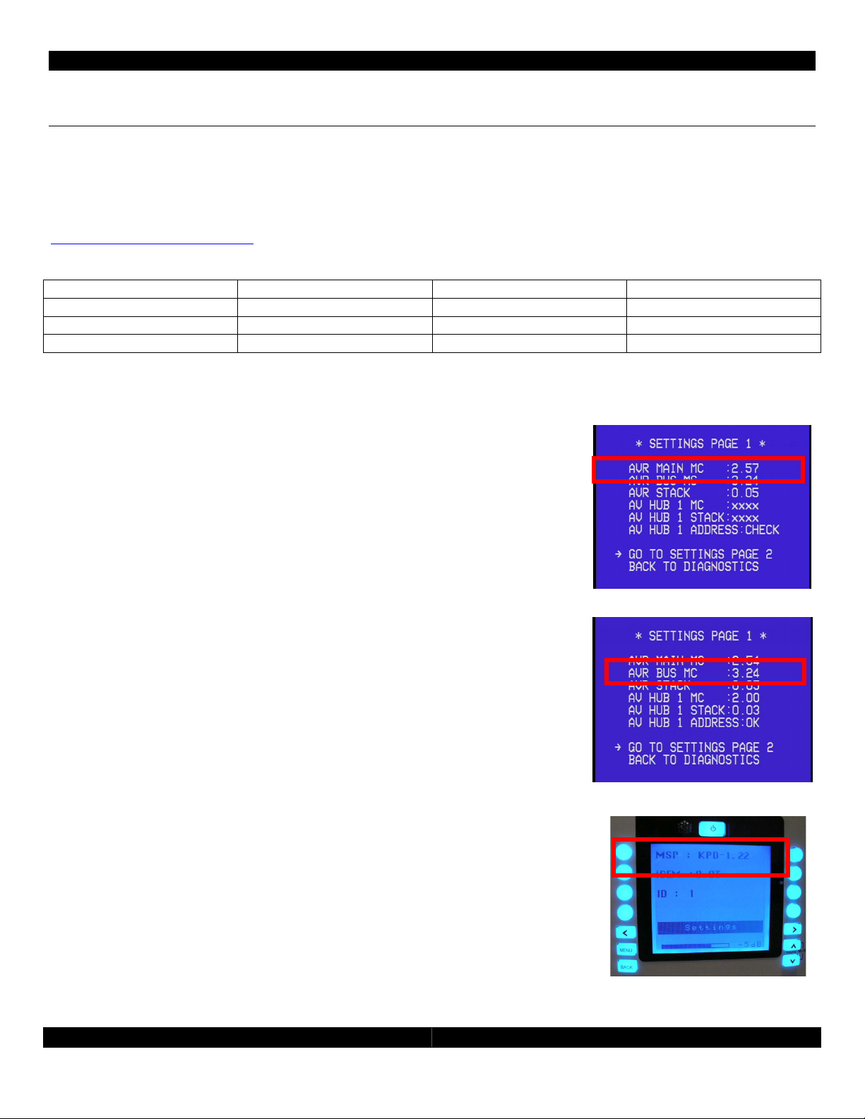
Identifyin Installed Firmware ..................................................................................................................... 3
Detailed Wirin Connection Dia ram............................................................................................................... 4
Hardware Connection and Confi uration....................................................................................................... 4
Door ID Confi uration Switch ..................................................................................................................... 4
DBM21 Connection to W.H.E.N. System .................................................................................................... 4
DBM21 Connection to Door-Phone Directly (Without Complete Phone System)............................... 4
DBM21 Connection to Door-Phone System.............................................................................................. 5
Door-Phone Camera Connection to W.H.E.N. System ........................................................................... 5
AVR21EN Setup ..................................................................................................................................................... 5
Assi n Doors and Cameras......................................................................................................................... 5
Name Doors .................................................................................................................................................. 5
Door Rin ....................................................................................................................................................... 5
Door Answer .................................................................................................................................................. 5
Door Open..................................................................................................................................................... 5
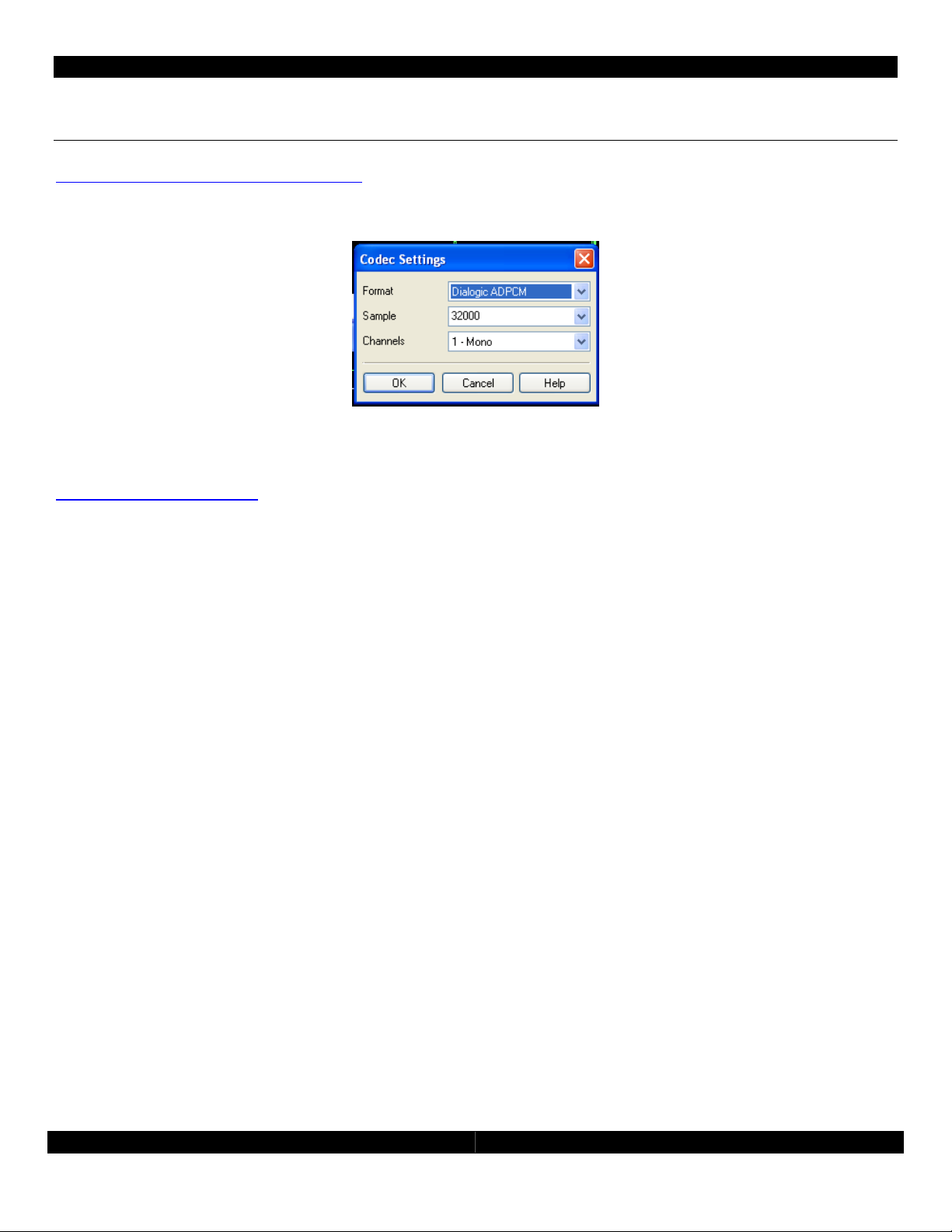
Custom Doorbell Chime...................................................................................................................................... 6
Features
•Provides doorbell chimes for the W.H.E.N. system
•Allows two-way communication to a Panasonic compatible door phone station with or without a
Panasonic phone system
•Compatible with Channel Vision™ DP Series door stations includin video from built-in cameras
•Allows any custom chime to be pro rammed (rin tones)
•Each AVH21 supports two DBM21
•Half size allows two units to be mounted side by side in a Leviton or a Channel Vision structured
wirin panels
•Supplies power to door station and door-station camera (if needed) over a sin le RJ-11
connection
Included Accessories
•2 WECO, screw-down Phoenix Connectors (Power In and Power Out),
•6 plastic overlays to select HUB/Door
•4 Mountin hardware (RICHCO snap in rivets), which are the same pieces used in AVH21 and
WPS21 for mountin to Leviton and Channel Vision structured wirin panels

- 3 -
DBM21 Installation and Instruction Guide - 3 -
W.H.E.N.™ Minimum System Requirements
The DBM21 doorbell module requires that the system have the followin software as a minimum.
Before installin the DBM21, it will be necessary to check the currently installed firmware of all your
components. If you need to update the firmware it will be necessary to contact Audioaccess
Technical Support at 888.691.4171 (USA only) or 516.496.3400 (Outside USA) or throu h email at
websupport@harman.com.
Component Firmware Version Found In
AVR21EN AVR MAIN MC Version 2.57 or later AVR21EN Dia nostics
AVR21EN AVR BUS MC Version 3.24 or later AVR21EN Dia nostics
KP21 KP MSP Version 3.18 or later KP21 Settin s
Identifying Installed Firmware
Identifying the AVR21EN Main CPU version
To verify the AVR21EN main CPU version, turn ON the avr and o to
the OSD menu under Dia nostics >Settin s pa e 1, version can be
read under AVR MAIN MC. In this example, main CPU version is 2.57.
Identifying the AVR1394 BU version
To verify the AVR1394 version, turn the AVR on and o to the OSD
menu under Dia nostics > Settin s Pa e 1, version can be read under
AVR BUS MC. In this example AVR1394 Bus version is 3.24.
Identifying the KP21 Firmware Version
The KP21 firmware version is displayed on the keypad display and not in
the receiver’s on screen menu. On the KP21, o to SETUP, press the ri ht
arrow on the keypad four times, press SETTINGS, the display will show
MSP, ICEM and ID for that particular keypad. In this example the KP21
version is 1.22.

- 4 -
DBM21 Installation and Instruction Guide - 4 -
Detailed Wiring Connection Diagram
Hardware Connection and Configuration
Door ID Configuration Switch
Two 2-position switches determine the door number as identified on the appropriate status panel label. The
individual labels are screened and “keyed” to match the two-position switch that sets the door number. There
are six keyed overlays for each combination of Door 1 and Door 2 options connected to up to three (3) AVH21.
The system allows a maximum of six doors, two per AVH21.
DBM21 Connection to W.H.E.N. System
The DBM21 needs to have two connections to the system, similar to a KP21. Power is supplied to the first DBM21
(if there are more then one) from the WPS21 usin up to a maximum14 au e, 4 conductor, unshielded wire,
and a minimum 16- au e, 2-conductor unshielded wire. This supplies 24v DC power to the DBM21. Multiple
DBM21 can be daisy chained for power. The second connection will use a standard CAT5e cable with RJ45
termination as is used in standard Ethernet connections. Note, these are not Ethernet connections and cannot
be connected to an internet port. Connect the each DBM21 to an open keypad connection on the AVH21. The
DBM21 takes the place of one of the active zones in the system.
DBM21 Connection to Door-Phone Directly (Without Complete Phone
System)
Usin CAT3, CAT4 or CAT5 wire, terminate the RJ-25 (RJ-11 with 6 conductors) connection
accordin to the dia ram shown here and the chart below. Refer to the door phone
instructions for proper connections at the door phone.
DBM21 Door Panel output, RJ11
Pin # Description Connect To: Note
1 Camera power Ground Door-Station Camera Power Ground Optional Camera
2 Door-Panel Si nal Out Phone Si nal + internally Connected to Pin 4
3 Door-Panel Ground Phone Si nal Ground Internally Connected to Pin 5
4 Door-Panel Si nal Out Phone Si nal + Internally Connected to Pin 2
5 Door-Panel Ground Phone Si nal Ground Internally Connected to Pin 3
6 Camera Power 12 Volt DC Door-Station Camera Power DC + Optional Camera
Power Out to next DBM21
Power In from AVH21
Uplink to AVH21
RJ-45
(
Key
pad communicatio
n bus)
Connection to door-phone station
RJ
-
25
(
RJ
-
11 with 6 conductors
)

- 5 -
DBM21 Installation and Instruction Guide - 5 -
DBM21 Connection to Door-Phone ystem
Terminate the RJ-25 (RJ-11 6 conductor) connection as in the chart above on both ends.
Connect the DBM 21 to a standard 3-way phone splitter. Connect the door-phone station,
the Panasonic phone system and the DBM21 to the splitter.
Door-Phone Camera Connection to W.H.E.N. ystem
The camera can be located inside the door-phone station (optional on Panasonic and Channel Vision models)
or can be a standard security camera located near the front door. The DBM21 will supply power for the internal
camera in the door station (if equipped). Usin standard coaxial (RG-6 or RG-59) cables connect the output of
the camera to an input on the AVH21. In the AVR21EN camera setup, be sure to assi n the camera input used
to the appropriate DBM21.
AVR21EN etup
Please see the AVR21EN installation manual for details. The AVR21EN can control how the doorbell chimes are
played throu h each zone, how the zones can interact with the door-phone station and if a security camera is
associated with a door-phone station.
Assign Doors and Cameras
To access the door setup o to the on-screen menu of the AVR21EN. From the main menu, select Zone Setup,
and then select Assi n Services. From the Assi n Services menu select the Door Setup menu. Select the doors
that are in use and the cameras (if any) assi ned to them.
Name Doors
From Zone Setup Pa e 1, select Name Doors. All doors in the system can be renamed.
Door Ring
From Zone Setup Pa e 2, select Setup By Number Pa e 2 and enable or disable door bell chimes for each
zone. The default is for all zones to rin always.
Door Answer
From Zone Setup Pa e 2, select Setup By Number pa e 2 and enable or disable door bell answer for each
zone. This will allow or block specific keypads from talkin to the door station. The default is for all zones to
answer all doors.
Door Open
From Zone Setup pa e 2, select Setup By Number pa e 3 and enable or disable door bell open for each zone.
This will allow or block specific keypads from openin the door locks if the system is usin the electronic door
locks on the AVH21. The default is for all zones to open all doors.

- 6 -
DBM21 Installation and Instruction Guide - 6 -
Custom Doorbell Chime
Usin Wave Pad Sound Editor (freeware which can be downloaded from
http://nch.com.au/wavepad/index.html), create desired doorbell sound file. The doorbell sound starts
approximately 0.5 seconds after the door button is pushed, so insert a 0.5 second silence at the be innin of
sound. Save file as: Dialo ic vox file; 32000K sample rate; mono.
After file is saved chan e extension from “.vox” to “.bin”. For example: “sound.vox” to “sound.bin”. Use this file
with W.H.E.N. Multi-Room Components Software Up rade (HK Up rader.exe). This software packa e can be
requested from Audioaccess Technical Support at 888.691.4171 (U.S.A. Only), or by email at
websupport@harman.com. Sound files can be loaded to all six DBM21 at once or to each DBM21 individually.
Up rade procedure is the same as Keypad or A/V Hub up rade; details are included with the up rade
software when received from Technical Support.

- 7 -
DBM21 Installation and Instruction Guide - 7 -

- 8 -
DBM21 Installation and Instruction Guide - 8 -
Harman Consumer Group
250 Crossways Park Drive
Woodbury, NY 117 7
www.audioaccess.com
www.support.audioaccess.com
E-mail: Websup[email protected]
516.4 6.3400
888.6 1.4171 (U.S.A. Only)
FAX: 516.682.3510
©2008 Harman International Industries, Incorporated. All rights reserved.
Audioaccess is a registered trade mark of Harman International Industries, Incorporated.
W.H.E.N. (Whole-House Entertainment Network) is a trademark of Harman International Industries,
Incorporated
Channel Vision is a trademark of Channel Vision Technologies
Table of contents
Popular Accessories manuals by other brands

Adler Europe
Adler Europe AD 7969 user manual

Power Breezer
Power Breezer PB4MAX user manual

Mielta
Mielta Fantom FLS-3304-11-10 Setup and operation manual

Neosens
Neosens Skidsens manual

Gleason Reel
Gleason Reel Dual Hose Reel-Direct Drive K-18 Installation and maintenance instructions

RADEMACHER
RADEMACHER DuoFern Installation and operating instrictions