AudioArts Engineering R-55 User manual

R-55 Audio Console
TECHNICAL MANUAL
March 2003

R-16 / Dec 1997
R-55 Audio Console Technical Manual - 1st EditionR-55 Audio Console Technical Manual - 1st Edition
R-55 Audio Console Technical Manual - 1st EditionR-55 Audio Console Technical Manual - 1st Edition
R-55 Audio Console Technical Manual - 1st Edition
©2003 Audioarts®Engineering*
AUDIOARTS ENGINEERING
600 Industrial Drive
New Bern, North Carolina 28562
252-638-7000
*a division of Wheatstone Corporation
R-55/ Mar 2003

page Contents – 1
R-55 / Mar 2003
CONTENTS
R-55 Technical Manual
Table of Contents
Chapter 1 – Installation
Unpacking the Console ............................................................. 1-2
CountertopMounting................................................................. 1-2
System Ground .......................................................................... 1-3
Power Supply ............................................................................. 1-5
PS-6040 Power Supply........................................................................................... 1-5
Failsafe Dual Redundant Supply............................................................................ 1-6
Energizing ............................................................................................................... 1-6
Audio and Control Wiring.......................................................... 1-6
ConnectionProcedures .......................................................................................... 1-6
Unbalanced Connections (analog audio) ............................................................... 1-6
Modules Layout.......................................................................... 1-7
Hand Crimp Tool Wiring Instructions ...................................... 1-8
Wiring Procedure - Double Connection to One Pin ................ 1-9
R-55 Modules Layout Drawing................................................ 1-10
Chapter 2 - Stereo Line Inputs
Module Overview........................................................................ 2-2
Internal Programming Options ................................................. 2-3
Mutes ...................................................................................................................... 2-3
Timer Restart .......................................................................................................... 2-3
Local/Ready ............................................................................................................ 2-3
Talkback.................................................................................................................. 2-3
Hook-ups..................................................................................... 2-4
ANALOG AUDIO CONNECTIONS......................................................................... 2-4
CONTROL CONNECTIONS................................................................................... 2-4
Remote ON & OFF ................................................................................................. 2-5
Cough ..................................................................................................................... 2-5
External START & STOP ....................................................................................... 2-5
Ready...................................................................................................................... 2-5
Talkback to Control Room ...................................................................................... 2-5
On Tally................................................................................................................... 2-6
Tally B ..................................................................................................................... 2-6
DB Connector Pinout Drawing.................................................. 2-7

page Contents – 2
R-55 / Mar 2003
CONTENTS
Chapter 3 - Output Module
Module Overview........................................................................ 3-2
Hook-ups..................................................................................... 3-3
DB-25 Connector - Audio ....................................................................................... 3-3
DB-9 Connector - Audio ......................................................................................... 3-3
DB-9 Connector - Control ....................................................................................... 3-3
Tally 1 and Tally 2................................................................................................... 3-4
DB Connector Pinout Drawing.................................................. 3-5
Chapter 4 - Control Room/Studio Module
Module Overview........................................................................ 4-2
Internal Programming Options ................................................. 4-3
Cue Interrupt........................................................................................................... 4-3
CR/Cue Mute .......................................................................................................... 4-3
Studio Mute............................................................................................................. 4-3
Studio Dim .............................................................................................................. 4-3
Hook-ups..................................................................................... 4-4
DB-25 Connector — AUDIO................................................................................... 4-4
DB Connector Pinout Drawing.................................................. 4-5
Chapter 5 - Superphone Module-optional
Module Overview........................................................................ 5-2
Caller Set-Ups ........................................................................................................ 5-2
Internal Programming Options ................................................. 5-3
Mutes ...................................................................................................................... 5-3
Timer Restart .......................................................................................................... 5-3
Gain Trimpot ........................................................................................................... 5-3
Hook-ups..................................................................................... 5-3
AUDIO CONNECTIONS......................................................................................... 5-3
CONTROL CONNECTIONS................................................................................... 5-3
Remote ON & OFF ................................................................................................. 5-4
External START & STOP ....................................................................................... 5-4
On Tally................................................................................................................... 5-4
DB Connector Pinout Drawing.................................................. 5-5
Chapter 6 - Line Preselector-optional
Module Overview........................................................................ 6-2
Internal Programming Options ................................................. 6-2
Hook-ups..................................................................................... 6-3
Left DB-25 “A” Connector — Audio Inputs ............................................................. 6-3
Left DB-25 “A” Connector — Audio Outputs .......................................................... 6-3
Right DB-25 “B” Connector — Audio Inputs........................................................... 6-3
DB Connector Pinout Drawing.................................................. 6-5

page Contents – 3
R-55 / Mar 2003
CONTENTS
Chapter 7 - Tape Remote Module-optional
Module Overview........................................................................ 7-2
DB Connector Pinout Drawings
START/STOP Function Control I/O........................................................................ 7-3
Full-Function Control I/O ........................................................................................ 7-4
Chapter 8 - Quad Mic Preamp
Overview ..................................................................................... 8-2
Internal Programming Options ................................................. 8-3
Phantom Power ...................................................................................................... 8-3
Hook-ups..................................................................................... 8-3
AUDIO INPUT CONNECTIONS............................................................................. 8-3
AUDIO OUTPUT CONNECTIONS......................................................................... 8-4
POWER CONNECTIONS....................................................................................... 8-5
Plug Terminal Pinout Drawing .................................................. 8-6
Installing the Optional QMP-4 Mic Preamp.............................. 8-7
Chapter 9 - Meterbridge
Overview ..................................................................................... 9-2
Digital Timer ............................................................................... 9-2
Chapter 10 - Parts List
SL-55 Stereo Line Input........................................................................................ 10-2
OM-55 Master Output ........................................................................................... 10-4
CRS-55 Control Room/Studio .............................................................................. 10-6
SPN-55 Superphone Input (optional) ................................................................... 10-8
LS-55 Line Selector (optional)............................................................................ 10-10
TR-55/FF Tape Remote (optional) ..................................................................... 10-11
TR-55/SS Tape Remote (optional)..................................................................... 10-12
QMP-4 Quad Mic Preamp .................................................................................. 10-13
MBE-55 Mother Board (Extender) ......................................................................10-14
MBR-55 Mother Board (Right)............................................................................ 10-15
Timer................................................................................................................... 10-16
Timer Display...................................................................................................... 10-18
PS-6040 Power Supply....................................................................................... 10-19
LED-3 Meter LED Lamp ..................................................................................... 10-21
R-55 Frame......................................................................................................... 10-22
R-55 Connector Kit ............................................................................................. 10-24
R-55 Console...................................................................................................... 10-25
R-55 Spare Parts Kit........................................................................................... 10-26

page Contents – 4
R-55 / Mar 2003
CONTENTS
Chapter 10 - Schematic Drawings
Console Flow Diagram ............................................................ 11-2
Stereo Line Input (SL-55)
schematic.............................................................................................................. 11-3
load sheet drawing................................................................................................ 11-6
Output Master (OM-55)
schematic.............................................................................................................. 11-7
load sheet drawing.............................................................................................. 11-10
Control Room/Studio (CRS-55)
schematic............................................................................................................ 11-11
load sheet drawing.............................................................................................. 11-14
Superphone Module (SPN-55)
schematic............................................................................................................ 11-15
load sheet drawing.............................................................................................. 11-18
Line Select (LS-55)
schematic............................................................................................................ 11-19
load sheet drawing.............................................................................................. 11-20
Tape Remote (TR-55)
schematic............................................................................................................ 11-21
load sheet drawing.............................................................................................. 11-22
Quad Mic Preamp (QMP-4)
schematic............................................................................................................ 11-23
load sheet drawing.............................................................................................. 11-24
Timer (CLK-220)
schematic............................................................................................................ 11-25
load sheet drawing.............................................................................................. 11-26
Timer Display (CLD-220)
schematic............................................................................................................ 11-27
load sheet drawing.............................................................................................. 11-28
Meter LED Lamp (LED-3)
schematic............................................................................................................ 11-29
load sheet drawing.............................................................................................. 11-30
Mother Board—Extender (MBE-2606)
schematic............................................................................................................ 11-31
load sheet drawing.............................................................................................. 11-32
Mother Board—Right (MBR-2000)
schematic............................................................................................................ 11-33
load sheet drawing.............................................................................................. 11-34
Power Supply (PS-6040)
schematic............................................................................................................ 11-35
load sheet drawing.............................................................................................. 11-36

INSTALLATION and POWER
page 1 – 1
R-55 / Mar 2003
Installation and Power
Chapter Contents
Unpacking the Console ............................................................. 1-2
CountertopMounting................................................................. 1-2
System Ground .......................................................................... 1-3
Power Supply ............................................................................. 1-5
PS-6040 Power Supply........................................................................................... 1-5
Failsafe Dual Redundant Supply............................................................................ 1-6
Energizing ............................................................................................................... 1-6
Audio and Control Wiring.......................................................... 1-6
ConnectionProcedures .......................................................................................... 1-6
Unbalanced Connections (analog audio) ............................................................... 1-6
Modules Layout.......................................................................... 1-7
Hand Crimp Tool Wiring Instructions ...................................... 1-8
Wiring Procedure - Double Connection to One Pin ................ 1-9
R-55 Modules Layout Drawing................................................ 1-10
INSTALLATION and POWER
page 1 – 2
R-55 / Mar 2003
Installation and Power
Unpacking the Console
TheR-55consoleisshippedastwopackages.Onecartoncontainsthe
console and the second carton contains the power supply, connecting
cable, connector kit and documentation.
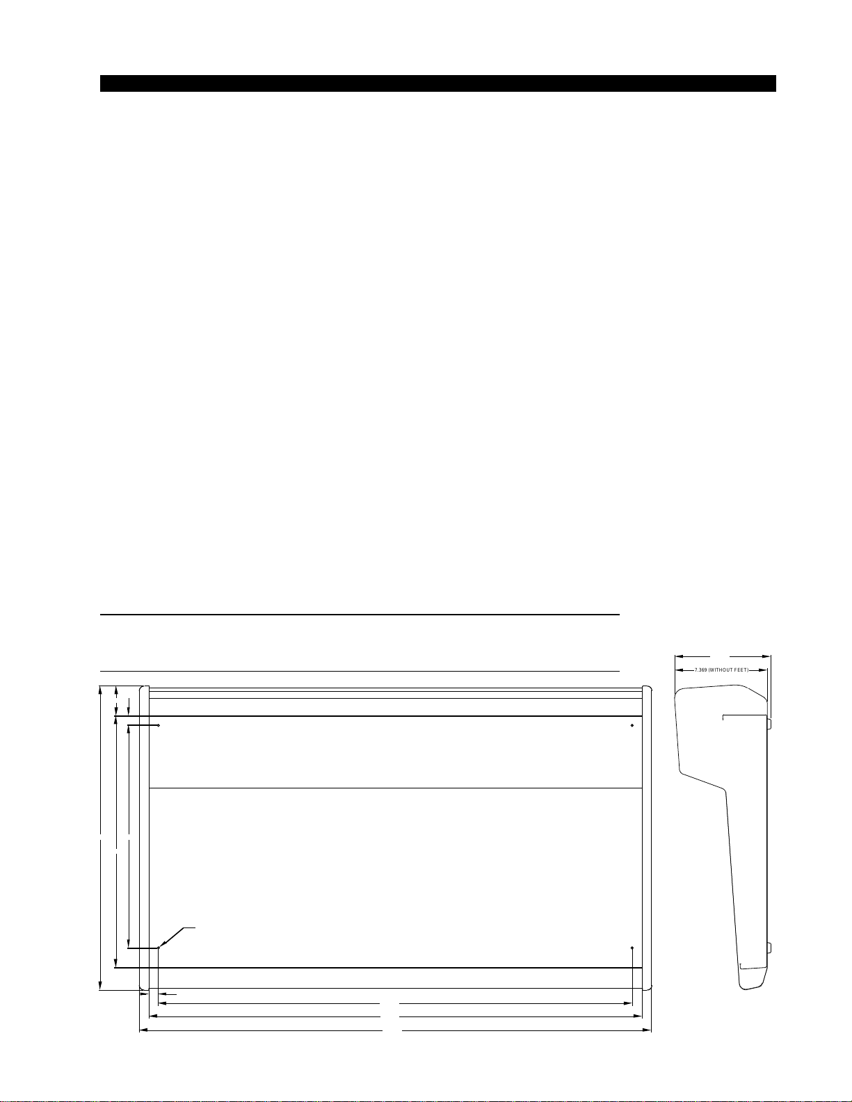
CountertopMounting
TheR-55audioconsoleisdesignedforcountertopmounting.Console
placementshould avoid proximity to any electromagneticfields, such as
largepowertransformers,motors,andfluorescentlightingfixtures.Ifyou
will be securing the console to the counter top, you may want to pre-drill
the mounting holes (see sketch below).
Set the console in place on the counter, and remove the screws that
hold down the first and the last modules in place (two per module).
Carefully remove those modules from the frame. Attach the console
mainframe to the counter top, using the holes provided in the bottom of
the chassis and screws appropriate to the counter material, and reinstall
the removed modules.
Theconsoleextendsapproximately75/8”abovethecountertopatthe
meterbridge.Thehingedmeterbridgewillrequire14”abovethecountertop
surface and 4 3/4” behind the rear meterbridge to open freely.
Do not connect the R-55 console to its power supply (and do not
connectthepowersupplytotheACpowerline)untilinstructedtodo
so.
NOTE:Thisconsolecon-
tains static-sensitive de-
vices. Normal precau-
tions against static dis-
charge should be ob-
served when handling
individual modules.
28.690
24.180
25.670
17.750
27.190
.760
7.369 (WITHOUT FEET)
7.6341
D = .171"; USE #8 SCREWS
2.356
20.044
.750
7.369 (WITHOUT FEET)
7.6341
INSTALLATION and POWER
page 1 – 3
R-55 / Mar 2003
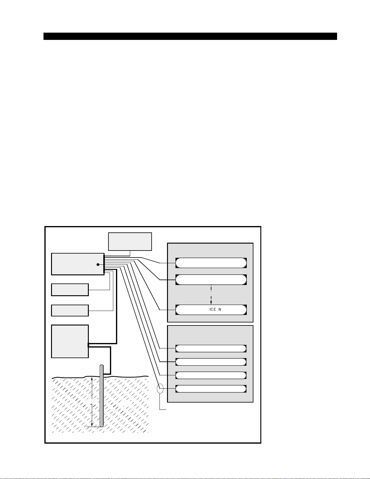
CONSOLE
2-TRACK
MULTI-TRACK
AC BREAKER
BOX
DEVICE 1
DEVICE 2
DEVICE N
CONSOLE POWER SUPPLY
CONTROL ROOM POWER AMP
STUDIO POWER AMP
OTHER
POWER COMPANY
EARTH GROUND
HEAVY
(#4 or #6)
COPPER
WIRE
HIGH POWER
EQUIPMENT RACK
COPPER ROD
SOIL
3-wire ground or separate wire run from chassis
EFFECTS RACK
MIC PANEL
GND
TYPICAL SYSTEM
GROUNDING SCHEME
etc.
3–5 ft.
Tie the console ground lug
terminal strip to the system
earthground. Tieeverypiece
of equipment in the entire
audio system to the console
ground lug terminal strip.
System Ground
The first step is to ground the console.
Note that as supplied from the factory, console rackmount power
supplycommon,audioground,andtheR-55mainframeareconnected
togetherattheconsole,butareNOTconnectedtoelectricalgroundand
the chassis of the power supply. Safety requirements dictate that a
positiveconnectionfromtheconsolemainframetoelectricalgroundbe
made in the completed installation. Use the grounding lug on the rear
of the mainframe to establish your system ground. The grounding lug
may be found at the rear of the console, on the rear frame panel, to the
left if you are looking at the rear of the console.
The system ground serves two important purposes:
(1) It provides a zero signal reference point for the entire audio system;
(2) It assures safety from electrical shock.
Thereexisttwotermsthatoneencountersinadiscussionofground:
(A)EARTHGROUND,whichisusuallyaheavycopperroddrivenintothe
soiladjacenttothebuilding(around6feetdown)oraconnectiontothecopper
water pipes leading into the building. Either is acceptable (unless, of course,
the water pipe is made of plastic).

INSTALLATION and POWER
page 1 – 4
R-55 / Mar 2003
(B) THE POWER COMPANY EARTH CONDUCTOR that enters the build-
ing at the power line breaker box; this conductor should be (and is often by code)
tiedto theabove-mentioned earth ground at one point. This point is the SYSTEM
EARTH GROUND.
TIE THE CONSOLE GROUND LUG TO THE SYSTEM EARTH
GROUND. TIE EVERY PIECE OF EQUIPMENT IN THE ENTIRE
AUDIO SYSTEM TO THE CONSOLE GROUND LUG. If the system
earthground point isinaccessible, tie theconsoleground lug tothe power
company earth conductor at the main breaker box (see drawing "Typical
Grounding Scheme" on previous page).
Each piece of equipment should be connected by its own ground wire
(usually the round third pin on the AC cord). This means that every AC
outlet must have a separate conductor run to the console ground lug; the
outletscannotbedaisy-chainedasisnormallyencounteredincommercial
and residential AC systems. Any equipment not supplied with 3-wire AC
cables must have individual ground wires (16 gauge or larger) connected
to their chassis grounds and then run to the console ground lug terminal
strip.
Further Grounding Details
Check all equipment to be absolutely certain that each unit is power
transformer isolated from the AC mains to prevent safety hazards.
It is assumed that in each piece of audio equipment the audio ground
and the chassis are tied together at some point. Any piece of equipment
lacking a grounded chassis is likely to be prone to interference problems.
Locateallunbalanced audioequipment inthe samerackifpossible,to
minimize chassis ground potential differences. It may also be helpful to
insulateeachpieceofunbalancedequipmentfromitsmountingrailsinthe
rackbymeansofnylon10-32screwsandinsulatingwashersbetweenrails
and faceplates.
Once the system is properly grounded, proceed with the console
power supply installation and connection (next section).

INSTALLATION and POWER
page 1 – 5
R-55 / Mar 2003
Power Supply
PS-6040 Power Supply
The R-55 console is powered by a model PS-6040 power supply.
Mount the PS-6040 power supply in a standard 19” equipment rack,
keepinginmindthatadequateventilationisnecessarytopreventheat
build-up within the rack.
Once the supply is rackmounted, it
should be connected to the console
using the factory supplied cable. The
cable has two different types of 9-pin
connectors on its end: a plastic shell
connectorthatconnectstotheconsole’s
power supply connector, and a multi-
pin cable-mount connector that plugs
into the PS-6040 power supply. The
console’s power supply connector is
mounted on the right side of the con-
sole meterbridge rear.
Notethatthe power supply cable’s
9-pin female connector has to be ro-
tated until its locating pins match the
male connector on the power supply.
Donotforceaconnectoron;itattaches
easilywhenproperlyaligned.Connect
thecablefirsttotheconsole,thentothe
rear of the rackmount power supply.
If you are using two supplies
(failsafe option), connect the long
power supply cable’s round power supply connector to the center
connector of the rackmount failsafe panel. Then connect one supply
with a short cable to either of the two remaining connectors on the
failsafe panel and connect the second supply with a short cable to the
last connector.
Note each power supply is fitted with a 3-wire grounded AC cord
thatshouldbepluggedinto a"clean"ACpower source,thatis,anAC
sourcethatfeedsonlythecontrolroomaudiogear.Thissourceshould
be a separate feed from those powering lighting, air-conditioning, or
any other non-audio machinery. The third pin ground wire of the AC
source should be tied to the central system ground point. Note that
whilethe ACpower cordground wire terminatesat thepower supply
chassis,itdoesNOTconnecttotheR-55consolecommon;theconsole
itself must be grounded separately. (See previous section, "System
Ground".)
The power feed recom-
mended in the text is of-
teninstalledandreferred
to in studios as an “iso-
lated AC ground” outlet.
It is usually orange in
color.
Iffailsaferedundantsup-
plieshavebeenordered,
you will be installing two
units and an additional
rackmount panel.
Power Supply
End
Console
1
2
3
4
+5V Digital
+5V Digital
Digital
C
ommon
Audio
C
ommon
PIN
7
4
6
1
PIN
9-pin Connector
Female
9-pin Connector
Female
Power Supply End Console End
5
6
7
8
N
/C
-18V
Audio
C
ommon
+40V Phantom
5
3
8
9
9
+18V
2
ORG
YEL
GRN
BLK
N/C
BLU
BRN
VIO
PS Cable Pinou
t
RED
ORG
YEL
GRN
BLK
N/C
BLU
BRN
VIO
RED
R-55 / Aug 2003

INSTALLATION and POWER
page 1 – 6
R-55 / Mar 2003
Failsafe Dual Redundant Supply
Wheatstone failsafe power supply systems use two separate rack-
mount power supplies for each piece of powered equipment. Though
either is capable of running a full load on its own, in failsafe operation
both units run in tandem: if one fails, the other takes over, assuring
uninterrupted operation.
In order for failsafe systems to perform as designed, always have
BOTH rackmount supplies powered up and connected to their associ-
ated equipment.
Energizing
Assuming the R-55 console mainframe is properly placed and
grounded, and its PS-6040 power supply correctly rackmounted and
connectedtotheconsole,youmaynowenergizethePS-6040rackmount
power supply by plugging it into the AC mains. The four LEDs on the
power supply front panel should light up to indicate the presence of
theirrespectivevoltages. Theconsole'sVU meterswillilluminate and
individual module switches will assume factory default settings.
Once you have verified proper power-up, turn off the rackmount powerOnce you have verified proper power-up, turn off the rackmount power
Once you have verified proper power-up, turn off the rackmount powerOnce you have verified proper power-up, turn off the rackmount power
Once you have verified proper power-up, turn off the rackmount power
supply to de-energize the console. You may now proceed to wire upsupply to de-energize the console. You may now proceed to wire up
supply to de-energize the console. You may now proceed to wire upsupply to de-energize the console. You may now proceed to wire up
supply to de-energize the console. You may now proceed to wire up
audio and control connections.audio and control connections.
audio and control connections.audio and control connections.
audio and control connections.
Audio and Control Wiring
AllaudioandcontrolI/OconnectionstotheR-55consolearemade
throughmultipinDB-25connectorslocatedonthetopofeachmodule.
The output module also has a DB-9 connector. The factory supplied
hand crimping tool is used for all I/O wiring connections to and from
the console (see instruction on page 1-8).
ConnectionProcedures
Assuppliedfromthefactory,theconsolerequiresnologicconnec-
tions to function. Therefore an orderly installation begins with the
audio wiring. Note this manual is organized by module type (inputs,
outputs,monitor modules, etc.); eachchapter contains detailed wiring
instructions for its module type. Proceed through the manual, chapter
by chapter, until all modules have been wired to suit your particular
installation requirements. Once proper audio operation is verified, go
back to each individual chapter and proceed with control wiring.
Unbalanced Connections (analog audio)
ANALOG INPUTS — Wire to the console with typical shielded
twoconductorcable(likeBelden9451),justasifyouwereconnecting
abalancedsource.Attheunbalancedsourcemachine’soutput,connect
theblackwire(LOW)totheshield.Ifthemachinehasa-10dBuoutput,
don’t hesitate to turn module input gain as high as is needed.

INSTALLATION and POWER
page 1 – 7
R-55 / Mar 2003
ANALOG OUTPUTS — R-55 consoles use an electronically bal-
anced output circuit. Care must be exercised when connecting them to an
unbalancedsystem. Whiletemporarily shortingthe low sideof theoutput
signal to ground will not cause any problems, continued operation will
result in increased distortion, decreased reliability, and possible oscilla-
tionproblems.Ifyoumustconnecttheoutputtoanunbalancedsystem,be
sure to leave the low side unterminated, and connect the unbalanced
system to the high side output and shield connections.
Modules Layout
TheR-55console’smainframecomessuppliedwith12linelevelinput
modules, an output module, and a control room/studio module. Each
module type has its assigned slot (see drawing on page 1-10). To handle
miclevelinputs,aquadmicpreampisincluded.Alsotherecanbeoptional
modules: a superphone, a line select module, and a tape remote module.
Optional modules can be placed in any input slot.
INSTALLATION and POWER
page 1 – 8
R-55 / Mar 2003
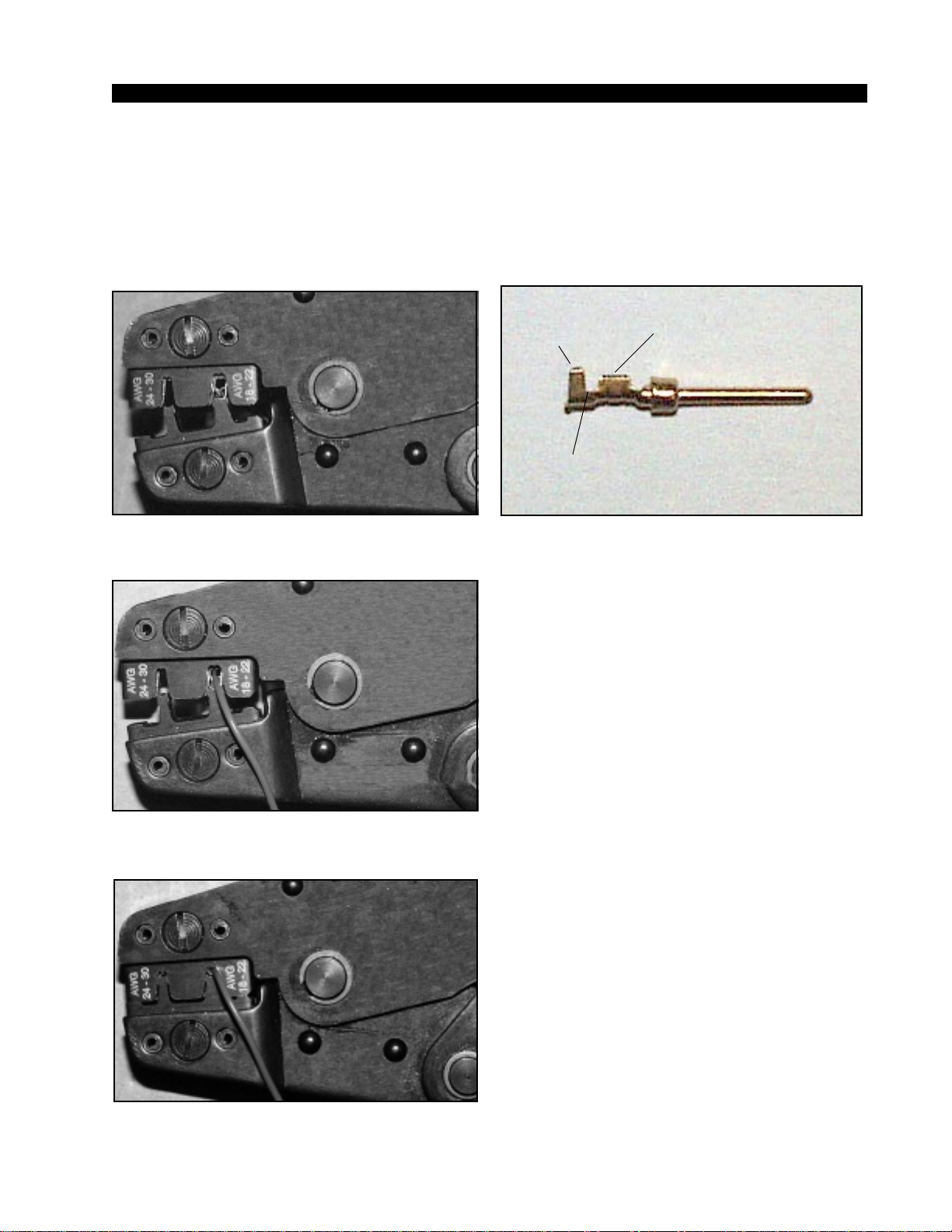
HAND CRIMP TOOL WIRING INSTRUCTIONS
The supplied hand crimping tool (W/S#850067) is used for all I/O wiring con-
nections to and from the console. It is to be used with the supplied pin (figure 1)
intended for 22"-28" gauge wire.
1) Strip wire approximately 3/16" (insert in
proper wire stripper, rotate one half turn, and
pull insulation off wire).
2) Leaving wire aside for the moment, with
crimping tool fully open (engraved side toward
you) bring a terminal into position from the
unmarked side of the tool. Place the conductor
tabs (inner set as shown in figure 1) on the
"18-22" or "24-30" (depending on the wire) an-
vil (slightly curved surface) so that the circular
portion of the tabs rests in the curved surface
of the anvil and the two tabs face up into the
walls of the female jaw. The insulation tabs will
be flush with the top of the tool (figure 2).
3) Close tool very slightly, only to the point
of holding the terminal in position (figure 2).
4) Insert wire into terminal until wire insu-
lation is stopped by conductor tabs (figure 3).
CRIMP by squeezing handles until jaws are fully
closed (figure 4).
5) If there is an insertion error or if a circuit
change is needed, you'll need to use an extrac-
tor tool to remove terminals (see next page).
Note that metallized plastic hoods for each
connector are also supplied with the console.
(1) Pin crimp terminal
CONDUCTOR
TABS
INSULATION
TABS
INSULATION
STOPS HERE
(2) The terminal conductor tabs (pointing UP) are
placed in anvil 18-22; the terminal's insulation tabs
extend in front towards the camera.
(3) The stripped wire is placed into the terminal and
crimped. Note the wire's insulation must stop just
short of the conductor tabs (detail)
(4) Final step: jaws fully closed; the insulation tabs
have been crimped.
R-55 / Jun 2004
INSTALLATION and POWER
page 1 – 9
R-55 / Mar 2003
(5) Place extractor tip over pin terminal to be
removed.
If you accidentally insert a crimp terminal
pin into the wrong socket, you'll need to use
the supplied pin extractor tool (W/S#850069)
to remove terminal pin, and correct your mis-
take without having to sacrifice a connector.
Place extractor tip (red side) over terminal pin
to be removed (figure 5), and press it down-
wards motion until tip rests upon Housing.
Then pull out the terminal pin from Housing.
It should never be necessary to discard a con-
nector due to a wiring error.
EXTRACTOR PIN INSTRUCTIONS
R-55 / Jun 2004 page 1 – 8a

INSTALLATION and POWER
page 1 – 9
R-55 / Mar 2003
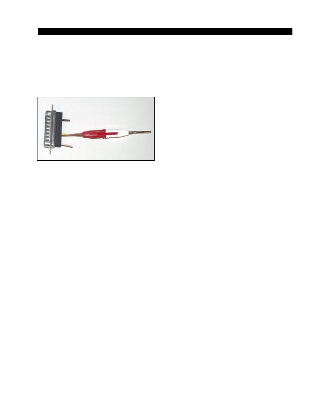
Wiring Procedure - Double Connection to One Pin
ref: DB-25 male multi-pin connector
Most audio equipment machine interfaces (as well as Wheatstone consoles) use
subminiature D-type connectors. Sometimes the interfaces require making two connec-
tions to a single DB pin. If the wiring has been set up using punchblocks, this is not a
problem; however, for situations where direct machine-to-console wiring is used, Wheat-
stone recommends the following procedure:
1) Connect the first wire to the desired pin as you normally would.
2) Note connector pins may easily be removed from the DB-25 shell with the wire still
attached: Hold the connector with the metal part down and observe its side. You
will see a row of "Vees"—simply press the top of the selected vee together with a
scribe or other sharp instrument; this will unlock the pin from the shell, allowing
it to be removed.
3) With the pin removed, strip out a short section of insulation from the connected
wire and wrap and solder the second wire to the first as shown above.
4) A short piece of heatshrink tubing (pictured here before being slid into place)
completes the connection.
5) Re-insert the pin into the DB-25 shell, spreading the vee apart to lock it in place.
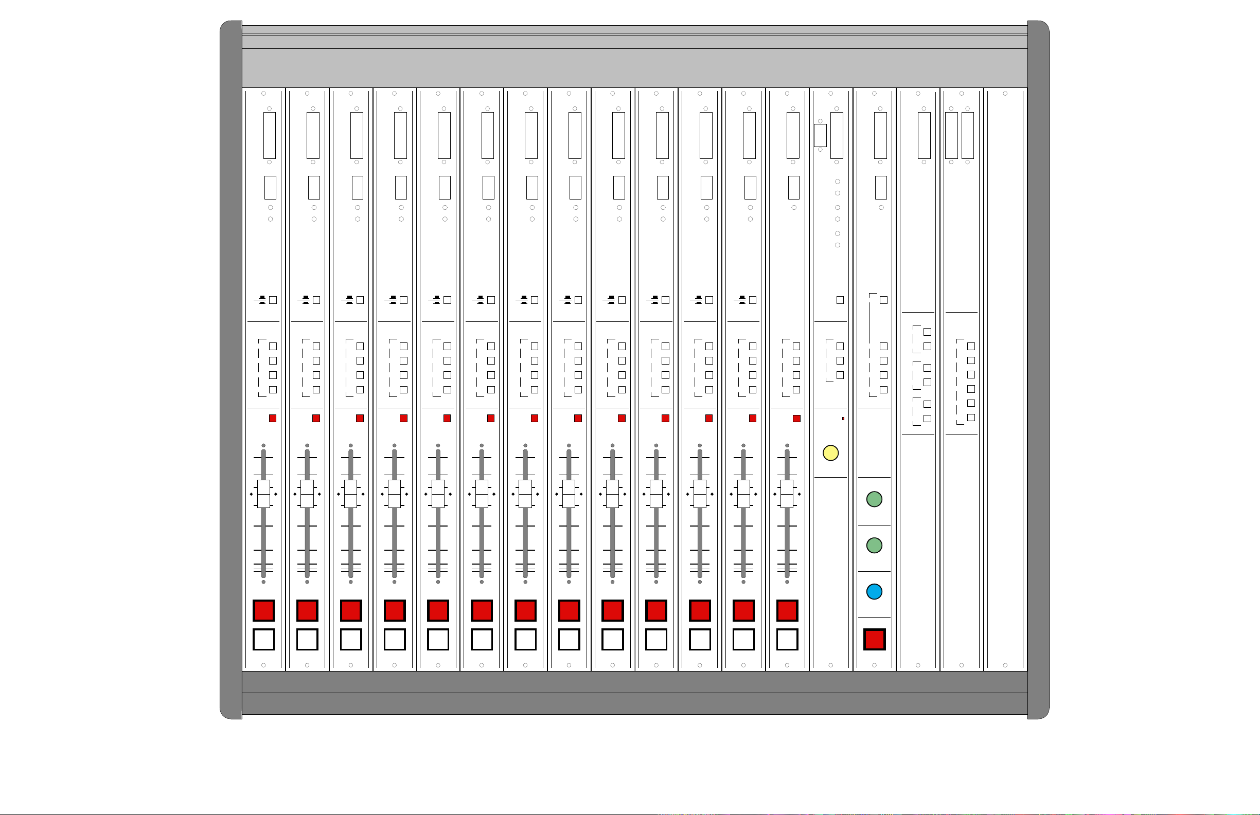
NOTE: 1. CONSOLE CAN ACCOMMODATE UP TO 13 INPUT MODULES (LINE AND OPTIONAL SUPERPHONE—SLOTS 1-13).
2. MASTER OUTPUT AND CONTROL ROOM/STUDIO MODULES HAVE THEIR DEDICATED SLOTS (AS SHOWN).
3. LAST THREE SLOTS AT THE RIGHT END OF THE FRAME SHOULD BE USED FOR OPTIONAL TAPE REMOTE OR ANY NON-POWERED OPTIONAL MODULES.
R-55 CONSOLE - MODULES LAYOUT page 1 - 10
R-55 / Mar 2003
LINE GAIN TRIM
LT
LOCAL OFF
TIMER RST
MUTE 1
MUTE 2
TB
CUE
START
STOP
SL
D
I
P
S
W
AUD
MONO
I/O
RT
PGM
SOURCE
ASSIGN
A
B
PR E
5
10
15
00
20
30
4O
50
0
LINE GAIN TRIM
LT
LOCAL OFF
TIMER RST
MUTE 1
MUTE 2
TB
CUE
START
STOP
SL
D
I
P
S
W
AUD
MONO
I/O
RT
PGM
SOURCE
ASSIGN
A
B
PR E
5
10
15
00
20
30
4O
50
0
LINE GAIN TRIM
LT
LOCAL OFF
TIMER RST
MUTE 1
MUTE 2
TB
CUE
START
STOP
SL
D
I
P
S
W
AUD
MONO
I/O
RT
PGM
SOURCE
ASSIGN
A
B
PR E
5
10
15
00
20
30
4O
50
0
LINE GAIN TRIM
LT
LOCAL OFF
TIMER RST
MUTE 1
MUTE 2
TB
CUE
START
STOP
SL
D
I
P
S
W
AUD
MONO
I/O
RT
PGM
SOURCE
ASSIGN
A
B
PR E
5
10
15
00
20
30
4O
50
0
LINE GAIN TRIM
LT
LOCAL OFF
TIMER RST
MUTE 1
MUTE 2
TB
CUE
START
STOP
SL
D
I
P
S
W
AUD
MONO
I/O
RT
PGM
SOURCE
ASSIGN
A
B
PR E
5
10
15
00
20
30
4O
50
0
LINE GAIN TRIM
LT
LOCAL OFF
TIMER RST
MUTE 1
MUTE 2
TB
CUE
START
STOP
SL
D
I
P
S
W
AUD
MONO
I/O
RT
PGM
SOURCE
ASSIGN
A
B
PR E
5
10
15
00
20
30
4O
50
0
LINE GAIN TRIM
LT
LOCAL OFF
TIMER RST
MUTE 1
MUTE 2
TB
CUE
START
STOP
SL
D
I
P
S
W
AUD
MONO
I/O
RT
PGM
SOURCE
ASSIGN
A
B
PR E
5
10
15
00
20
30
4O
50
0
LINE GAIN TRIM
LT
LOCAL OFF
TIMER RST
MUTE 1
MUTE 2
TB
CUE
START
STOP
SL
D
I
P
S
W
AUD
MONO
I/O
RT
PGM
SOURCE
ASSIGN
A
B
PR E
5
10
15
00
20
30
4O
50
0
LINE GAIN TRIM
LT
LOCAL OFF
TIMER RST
MUTE 1
MUTE 2
TB
CUE
START
STOP
SL
D
I
P
S
W
AUD
MONO
I/O
RT
PGM
SOURCE
ASSIGN
A
B
PR E
5
10
15
00
20
30
4O
50
0
LINE GAIN TRIM
LT
LOCAL OFF
TIMER RST
MUTE 1
MUTE 2
TB
CUE
START
STOP
SL
D
I
P
S
W
AUD
MONO
I/O
RT
PGM
SOURCE
ASSIGN
A
B
PR E
5
10
15
00
20
30
4O
50
0
LINE GAIN TRIM
LT
LOCAL OFF
TIMER RST
MUTE 1
MUTE 2
TB
CUE
START
STOP
SL
D
I
P
S
W
AUD
MONO
I/O
RT
PG M
SOURCE
ASSIGN
A
B
PR E
5
10
15
00
20
30
4O
50
0
LINE GAIN TRIM
LT
LOCAL OFF
TIMER RST
MUTE 1
MUTE 2
TB
CUE
START
STOP
SL
D
I
P
S
W
AUD
MONO
I/O
RT
PGM
SOURCE
ASSIGN
A
B
PR E
5
10
15
00
20
30
4O
50
0
AUD TRIM
LT
METERS
OM
MONO
TRIM
LT
SWITCHED
AUD
RT
RT
EXT
PGM
PGM
MONO/
SOURCE
10
9
8
7
64
3
2
1
0
5
CUE
B
I/O
A
I/O
PR E
PR E
CUE
CRS
T
10
9
8
7
64
3
2
1
0
5
CR
10
9
8
7
64
3
2
1
0
5
HDPN
10
9
8
7
64
3
2
1
0
5
STUDIO
SOURCE
B
AUD
MONO
PGM
EXT
TB GAIN TRIM
PR E
I/O
CR CUE LT
CR CUE RT
HDPN CUE
CR MUTE
ST DIM LT
ST DIM RT
D
I
P
S
W
ST MUTE
LS
1
2
3
4
5
6
B
I/O
A
I/O
SOURCE
STOP
REC
REMOTE
I/O
TR
RTZ
FF
EWR
APL Y
SPN
I/O
CALLER GAIN TRIM
D
I
P
S
W
TIMER RST
MUTE 1
MUTE 2
ASSIGN
AUD
MONO
PGM
PR E
UEC
OFF
NO
CALLER
5
10
15
00
20
30
4O
50
0

page 2 – 1
R-55 / Mar 2003
STEREO LINE INPUT
Stereo Line Input (SL-55)
Chapter Contents
Module Overview........................................................................ 2-2
Internal Programming Options ................................................. 2-3
Mutes ...................................................................................................................... 2-3
Timer Restart .......................................................................................................... 2-3
Local/Ready ............................................................................................................ 2-3
Talkback.................................................................................................................. 2-3
Hook-ups..................................................................................... 2-4
ANALOG AUDIO CONNECTIONS......................................................................... 2-4
CONTROL CONNECTIONS................................................................................... 2-4
Remote ON & OFF ................................................................................................. 2-5
Cough ..................................................................................................................... 2-5
External START & STOP ....................................................................................... 2-5
Ready...................................................................................................................... 2-5
Talkback to Control Room ...................................................................................... 2-5
On Tally................................................................................................................... 2-6
Tally B ..................................................................................................................... 2-6
DB Connector Pinout Drawing.................................................. 2-7

page 2 – 2
R-55 / Mar 2003
STEREO LINE INPUT
Stereo Line Input (SL-55)
Module Overview
SL-55 modules are for stereo line input signals.
Eachmoduleacceptstwostereosources:AandB,switchedatthetop
ofthemodule.Recessedfrontpanelmulti-turntrimpotsadjusttheleftand
right levels. Output switches assign the selected source signal to any
combination of the console’s four outputs: two stereo outputs—PGM
(program) and AUD (audition); and two mono outputs—MONO and
PRE.NOTE: the module does not needto be ON to feed thePRE output.
A CUE switch places the module’s signal on the console’s cue bus,
whereitmay beheardon themeterbridgemounted cuespeakerand/or as
an interrupt to the console operator’s headphones and/or control room
monitorspeakers.Thevariouscueinterruptmodesareprogrammedatthe
console’s CRS-55 (Control Room/Studio) module via PCB-mounted
dipswitch. See page 4-3.
Level is set by a long-throw fader.
ChannelON(START)andOFF(STOP)switchesareatthebottomof
the module. In addition to being controlled remotely, these can also be
programmed(via internal PCB-mounteddipswitch) toperforma variety
of functions, including starting and stopping external source machines,
activating control room and studio mutes, external tallies, and timer
restart. The STOP switch’s LED can be controlled by an external source
machine to act as a “ready” indicator.
Allaudioand controlinput andoutput signalsaremadeviathe multi-
pin DB-25 connector mounted on the top of the module and located
underneath the hinged meterbridge.
LL
LLIIIINN
NNEE
EE
GG
GGAA
AAIIIINN
NN
TT
TTRR
RRIIIIMM
MM
LL
LLTT
TT
LL
LLOO
OOCC
CCAA
AALL
LL
OO
OOFF
FFFF
FF
TT
TTIIIIMM
MMEE
EERR
RR
RR
RRSS
SSTT
TT
MM
MMUU
UUTT
TTEE
EE
11
11
MM
MMUU
UUTT
TTEE
EE
22
22
TT
TTBB
BB
CC
CCUU
UUEE
EE
SS
SSTT
TTAA
AARR
RRTT
TT
SS
SSTT
TTOO
OOPP
PP
SL
DD
DD
IIII
PP
PP
SS
SS
WW
WW
AA
AAUU
UUDD
DD
MM
MMOO
OONN
NNOO
OO
IIII//
//OO
OO
RR
RRTT
TT
PP
PPGG
GG MM
MM
WW
WW##
##
00
0022
2277
7700
0000
0000
00AA
AA
SS
SSOO
OOUU
UURR
RRCC
CCEE
EE
AA
AASS
SSSS
SSIIIIGG
GGNN
NN
AA
AA
BB
BB
PP
PPRR
RR EE
EE
55
55
11
1100
00
11
1155
55
00
00
00
00
22
22 00
00
33
33 00
00
44
44OO
OO
55
5500
00
00
00

page 2 – 3
R-55 / Mar 2003
STEREO LINE INPUT
Internal Programming Options
All internal programming is made via PCB mounted dipswitch SW1
locatedonthetopofthemodule(beneaththeDB-25connector).Notethat
when a dipswitch position is thrown to the right it is ON.
Mutes
An SL-55 module can be programmed to mute speakers when the
channelisON.TheR-55consolehastwomutecontrollines:controlroom
andstudio. Each of theseisactivated by an Ainputsource. The dipswitch
SW1 programs these muting functions:
SW1 position 4 mutes the studio when source A is ON
SW1 position 5 mutes the control room when source A is ON
Timer Restart
The console’s digital timer can be programmed to automatically reset
to zero and begin counting up when the module’s ON button is pressed.
SW1 position 6 activates timer restart
Local/Ready
The module’s channel OFF switch normally has its LED indicator
controlled by the switch itself (Local). This is the factory default setting.
However, should you wish to have the LED function as a Ready light for
anexternalsourcemachine,dipswitchSW1position7,whenthrowntothe
left, passes control to the Ready input on the module’s DB-25 connector.
A closure between the Ready input (DB-25 pin 2) and Digital Ground
(DB-25 pin 19) will activate the OFF switch LED. As long as the closure
is maintained, the LED will be lit.
Talkback
Typically,oneoftheR-55console’sinputmoduleswillbeusedforthe
controlroom(CRS)consoleoperator’smicrophone.The thirdpositionof
the dipswitch SW1 allows that microphone to also function as a talkback
mic.Itplacesthesignal(pre-fader,pre-on/off)ontotheconsole’stalkback
bus. When the console operator presses a TB switch on the console’s
CRS-55ControlRoom/Studiomodule,thetalkbackbus(whichiscarrying
his microphone signal) will interrupt the regular monitor signal being fed
to the studio and talent will hear his voice through the studio monitor
speakers.
In order for the studio to reply to the console operator, the SL-55
module controlling the studio’s microphone signal must be routed to the
console’scuebus,whereitcaninterrupt theregularcontrol roommonitor
feedandbeheardbytheoperator.Thisisaccomplishedbyauser-supplied
TB switch in the studio. The switch provides a momentary closure
?
Table of contents
Other AudioArts Engineering Recording Equipment manuals

AudioArts Engineering
AudioArts Engineering D-75 User manual

AudioArts Engineering
AudioArts Engineering D-70 User manual

AudioArts Engineering
AudioArts Engineering R-5 User manual

AudioArts Engineering
AudioArts Engineering D-16 User manual

AudioArts Engineering
AudioArts Engineering R-60 User manual

AudioArts Engineering
AudioArts Engineering D-76 User manual
Popular Recording Equipment manuals by other brands


National Instruments
National Instruments NI 951x user manual

Black Lion Audio
Black Lion Audio PBR TRS3 Patchbay owner's manual

Nady Audio
Nady Audio MSE-100A owner's manual

Symetrix
Symetrix 488 DYNA-Squeeze Service manual

Lexicon
Lexicon 200 owner's manual

Radial Engineering
Radial Engineering STAGEDIRECT user guide


