AudioArts Engineering D-70 User manual

D-70 Digital Audio
Console
TECHNICAL MANUAL
April 2000

R-16 / Dec 1997
D-70 Digital Audio Console Technical Manual - 1st Edition
©2000 Audioarts®Engineering*
AUDIOARTS ENGINEERING
600 Industrial Drive
New Bern, North Carolina 28562
252-638-7000
*a division of Wheatstone Corporation
D-70 / Apr 2000

ATTENTION
READ ME!
D-70 / Feb 2002
Attention!
Federal Communications Commission (FCC)
Compliance Notice:
Radio Frequency Notice
NOTE: This equipment has been tested and found to comply with the
limitsforaClassAdigitaldevice,pursuanttoPart15oftheFCCrules.These
limits are designed to provide reasonable protection against harmful
interference when the equipment is operated in a commercial environment.
This equipment, generates, uses and can radiate radio frequency energy
and, if not installed and used in accordance with the instruction manual,
may cause harmfulinterference to radio communications.Operation ofthis
equipment in a residential area is likely to cause harmful interference in
which case the user will be required to correct the interference at his own
expense.
!
This is Class A product. In a domestic environment,
thisproductmaycauseradiointerference,inwhichcase,
the user may be required to take appropriate measures.
This equipment must be installed and wired properly in order to assure
compliance with FCC regulations.
Caution! Any modificationsnot expressly approved in writing by
Audioartscouldvoidtheuser'sauthoritytooperatethisequipment.

ATTENTION
READ ME!
D-70 / Apr 2000
Attention!
This console contains static sensitive devices:
Normal precautions against static discharge should be observed when
handling individual modules. In particular, modules being packed for shipping
for return or repair must be packed in special static protection bags before
packaging. Damage caused by static discharge may not be covered under
warranty.
Replacing Modules in a Powered-up Console:
While in an emergency situation it is possible to remove and insert modules
on a powered-up console, Wheatstone does not recommend this procedure.
Whenever possible it is best to power down the console first before removing
or replacing modules.
However, if you find you must proceed with this operation, then be sure to
take the following precaution:
When re-inserting a module, take care to replug it squarely into its
mainframe connector socket, so all edgecard fingers make contact
simultaneously. In other words, the gold-plated bus connector fingers on the
bottom edge of the module's printed circuit board must be inserted squarely
(i.e., perpendicular) to the mating socket on the bottom pan of the console
mainframe. The intent is to prevent a situation where one of the module's
power pins makes significant contact before the others. (Naturally, this
same precaution must be taken when using extenders.)
If the above instructions are followed the procedure should be routine; if they
are not, you could run the risk of damaging the console's logic chips.
Again, to avoid ANY possibility of this damage, whenever possible we
strongly recommend powering down the consolebefore replacing any modules.
!

READ ME!
D-70 / Oct 2000
IMPORTANT!
D-70 Audio Levels
General
All professional digital audio broadcast consoles manufactured by Wheatstone
are hybrid in nature. That is, they allow the user to connect both analog and
digital domain sources and provide both analog and digital outputs. While this
approach allows for greater flexibility when interconnecting source and
destination equipment, the user must be aware of what levels to expect when
applying, say a digital input and measuring at a analog output.
Gain Structure
Broadcast consoles by design have various electronic stages at which the
signal level may be amplified or attenuated. The primary stages are the A-D
converterinput,channel fader,DSPmixingandthebusoutputD-Aconverters.
The sum of these gain stages is commonly referred to as the console’s “gain
structure”. Wheatstone consoles are factory calibrated for 0dB or “unity gain”
when the input channel fader is set to nominal (-12dB).
The following is a stage by stage breakdown of a typical console’s gain stages:
Analog Input (A-D Converter)
• trim pots located on the ADC input circuit cards are trimmed so that a
+4dBU input signal will yield a -20dBFS digital output with the channel fader
at nominal. Trim pot gain range at this stage allows for interfacing unbalanced
equipment . Mic level ADC circuit cards have trim pots for matching various
microphone source levels to the console’s operating level.
Digital Fader Gain
• is set via CPU jumpers for 12dB of gain with the fader all the way up. Other
fadergain settings are possible, consult withthefactoryforrecommendations.
DSP Gain
• set in firmware for unity gain, digitalattenuation may be applied on a channel
by channel basis from the supplied Windows™ software application, VDip™.
Analog Bus Output Gain (D-A Converter)
• trim pots located on the corresponding analog output DAC circuit card are
factory trimmed so that a -20dBFS digital input signal will yield a +4dBu
analog output with the channel fader at nominal. These may be adjusted over
a range of -26 to -10dBFS = +4dBu.

READ ME!
D-70 / Oct 2000
Audio Reference Levels
All consoles are fully factory calibrated and will comply with the following reference
level:
-20dBFS digital = +4dBu analog = 0VU Note: 0dBu = .775v rms
+4dBu = 1.23v rms
These settings will provide a headroom of 20dB over the nominal input signal of +4dBu
analog, or -20dBFS digital. Should your facility require a different A-D - D-A reference
level please consult the factory for calibration details and/or alternate solutions.
Note that due to the lack of level standards in the digital domain, headroom available
for digital sources will be entirely dependant on the source. In fact, CD's are frequently
made with less than 1dB of digital headroom, and any boosting of digital CD levels in
the console by moving the fader up above the nominal can result in overload distortion
for that channel.For thisreason,the VDipset-up program allows fordigitalattenuation
on a fader by fader basis; digital sources can be conveniently attenuated this way to
guard against digital overload caused by not enough headroom on the digital source.
Since the D-70 console meters are true digital reading meters, they will always show
the console's digital levels, and whether there are any "overs" in the signal. By pressing
a channel's "CUE" button, the switched meters will show the digital level of that
channel's source, as configured with the VDip program. By using the program and
watching these meters, the amount of attenuation can be adjusted to meet your
headroom requirements.
Typical Input Levels
Mic Inputs Nominal = -50dBm, 150ΩMaximum = -26dBm
Analog Inputs Nominal = +4dBu Maximum = +24dBu
Digital Inputs Nominal = -20dBFS Maximum = 0dBFS
IMPORTANT

page Contents – 1
D-70 / Apr 2000
CONTENTS
D-70 Technical Manual
Table of Contents
Chapter 1 – Installation and Power
Unpacking the Console ............................................................. 1-2
CountertopMounting................................................................. 1-2
Modules and Rear Panels Layout............................................. 1-3
Rear panels Installation............................................................. 1-3
D-70 Modules Layout Drawing.................................................. 1-4
D-70 Rear Panels Layout Drawing............................................ 1-5
System Ground .......................................................................... 1-6
Power Supply ............................................................................. 1-7
The SPS-16 Power Supply..................................................................................... 1-8
Power Supply Cable Pinout.................................................................................... 1-8
Energizing ............................................................................................................... 1-9
Audio and Control Wiring.......................................................... 1-9
ConnectionProcedures .......................................................................................... 1-9
Digital Connections................................................................................................. 1-9
Analog Insert Points.............................................................................................. 1-10
Unbalanced Connections (analog audio) ............................................................. 1-10
Hand Crimp Tool Wiring Instructions.................................................................... 1-11
Chapter 2 - Input Module
Module Overview........................................................................ 2-2
Internal Programming Options ................................................. 2-3
Insert Bypass .......................................................................................................... 2-3
Phantom Power ...................................................................................................... 2-3
Talkback.................................................................................................................. 2-3
VDT Programming Options ....................................................... 2-4
Hook-ups..................................................................................... 2-4
Microphone Inputs ..................................................................... 2-4
Audio Connections.................................................................................................. 2-4
Control Connections ............................................................................................... 2-4
Remote ON & OFF ................................................................................................. 2-5
Cough ..................................................................................................................... 2-5
Talkback to Control Room ...................................................................................... 2-5
On Tally................................................................................................................... 2-5
Off Tally................................................................................................................... 2-6
Tally B ..................................................................................................................... 2-6
D-70 / Aug 2003

page Contents – 2
D-70 / Apr 2000
CONTENTS
Stereo Line Analog Inputs............................................................2-6
Audio Connections.................................................................................................... 2-6
Stereo Line Digital Inputs.............................................................2-7
Audio Connections.................................................................................................... 2-7
Control Connections ................................................................................................. 2-7
Remote ON & OFF ................................................................................................... 2-7
External START & STOP ......................................................................................... 2-8
Ready........................................................................................................................ 2-8
Tally B ....................................................................................................................... 2-8
Mono Mic Input Signal Flow Diagram .........................................2-9
Stereo Line Input Signal Flow Diagram .....................................2-10
Chapter 3 - Master Outputs
Overview ........................................................................................3-2
Internal Programming Options ....................................................3-2
Sampling Frequency for Console Outputs ............................................................... 3-2
Hook-ups........................................................................................3-4
OMA-70 Connections — Analog Audio Outputs ...................................................... 3-4
OMD-70 Connections — Digital Outputs.................................................................. 3-5
Master Outputs Signal Flow Diagram .........................................3-6
Chapter 4 - Control Room Module
Module Overview...........................................................................4-2
Internal Programming Options ....................................................4-3
Cue Interrupt............................................................................................................. 4-3
Cue Mute .................................................................................................................. 4-3
Hook-ups........................................................................................4-3
CRD-70/1 Rear Panel — Audio................................................................................ 4-3
CRD-70/2 Rear Panel — Audio................................................................................ 4-4
CRD-70/2 Rear Panel — Control ............................................................................. 4-4
Control Room Monitor Signal Flow Diagram..............................4-5
Chapter 5 - Studio Control Module
Module Overview...........................................................................5-2
Internal Programming Options ....................................................5-3
External Talkback Mute/Dim..................................................................................... 5-3
Studio Dim ................................................................................................................ 5-3
Hook-ups........................................................................................5-3
CRD-70/1 Rear Panel — Audio................................................................................ 5-3
CRD-70/2 Rear Panel — Audio................................................................................ 5-4
CRD-70/2 Rear Panel — Control ............................................................................. 5-4
Studio Monitor Signal Flow Diagram ..........................................5-5
D-70 / Sep 2000

page Contents – 3
D-70 / Apr 2000
CONTENTS
Chapter 6 - CPU & DSP Processors
Overview ........................................................................................6-2
CPU.................................................................................................6-2
DSP.................................................................................................6-4
D-70 Serial Interface......................................................................6-4
Using the Serial Interface ......................................................................................... 6-4
Internal Programming Options ....................................................6-6
Global Settings ......................................................................................................... 6-6
RS-485/RS-232Select ............................................................................................. 6-7
RS-485 Termination.................................................................................................. 6-7
Hook-ups........................................................................................6-7
DB-15 Connector — Digital Control Ports ................................................................ 6-7
DB Connector Pinout Drawing.....................................................6-8
CPU/DSP Signal Flow Diagram....................................................6-9
Chapter 6 - Virtual Dip Switch
Virtual Dip Switch Application Program .....................................7-2
Installation................................................................................................................. 7-2
Hooking up the computer ......................................................................................... 7-2
Running the program ................................................................................................ 7-3
Using the program .................................................................................................... 7-5
Input attenuation ....................................................................................................... 7-8
Advanced operation................................................................................................. 7-10
Ending the program ................................................................................................. 7-12
Serial Interface Cable DB Connectors Pinout Drawing ............7-13
Chapter 8 - Superphone Input Module
Module Overview...........................................................................8-2
Caller Set-Ups .......................................................................................................... 8-2
Automatic Features................................................................................................... 8-3
Inputs and Outputs ................................................................................................... 8-3
Internal Programming Options ....................................................8-3
Cue Pre/Post ............................................................................................................ 8-3
Mutes ........................................................................................................................ 8-4
Timer Restart ............................................................................................................ 8-4
Tallies........................................................................................................................ 8-4
Cue Dropout.............................................................................................................. 8-4
Gain Trimpots ........................................................................................................... 8-4
Hook-ups........................................................................................8-5
Audio Connections.................................................................................................... 8-5
Audio and Control Connections................................................................................ 8-5
Superphone Module Signal Flow Diagram .................................8-6
D-70 / Sep 2000

page Contents – 4
D-70 / Apr 2000
CONTENTS
Chapter 9 - Line Preselector Module
Module Overview...........................................................................9-2
Internal Programming Options ....................................................9-2
Hook-ups........................................................................................9-3
Audio Inputs (1-4) ..................................................................................................... 9-3
Audio Inputs (5-7) and Outputs ................................................................................ 9-4
Line Preselector Signal Flow Diagram........................................9-5
Chapter 10 - Tape Remote Module
Module Overview..........................................................................10-2
Hook-ups.......................................................................................10-3
Upper Connector — Control .................................................................................... 10-3
Lower Connector — Control .................................................................................... 10-3
Chapter 11 - Meterbridge
Overview .......................................................................................11-2
Replacement Parts.......................................................................11-2
Digital Timer .................................................................................11-2
Console Clock ..............................................................................11-3
Controls.................................................................................................................... 11-3
Setting the time........................................................................................................ 11-3
Capacitor Backup .................................................................................................... 11-3
Operational Modes .................................................................................................. 11-4
Clock/Timer(CLK-70)
Schematic ................................................................................................................ 11-5
Load Sheet............................................................................................................... 11-6
Clock/Timer Display (CLD-70)
Schematic ................................................................................................................ 11-7
Load Sheet............................................................................................................... 11-8
Chapter 12 - I/O Schematic Drawings & Load Sheets
Mono Mic ADC I/O Card Schematic (MMADC-70) ................................................ 12-2
Analog Stereo Line ADC I/O Card Schematic (SLADC-70)................................... 12-3
Digital Stereo Line SRC I/O Card Schematic (SRC-74) ........................................ 12-4
Digital Stereo Output I/O Card Schematic (OMD-70) ............................................ 12-5
Analog Stereo Output I/O Card Schematic (OMA-70) ........................................... 12-6
Monitor 1 Control Room/Studio I/O Schematic (MON1-70) ................................... 12-7
Monitor 2 Control Room/Studio I/O Schematic (MON2-70) ................................... 12-8
Superphone I/O Card Schematic (SPIO-70) .......................................................... 12-9
Line Select Relay I/O Card Schematic (LSR-70) .................................................. 12-10
Mono Mic ADC Card Load Sheet (MMADC-70)..................................................... 12-11
Analog Stereo Line ADC Card Load Sheet (SLADC-70) ...................................... 12-12
D-70 / Mar 2003

page Contents – 5
D-70 / Apr 2000
CONTENTS
Digital Stereo Line SRC Card Load Sheet (SRC-74)............................................ 12-13
External Sync Card Load Sheet (ESYN-70) .......................................................... 12-14
Digital Stereo Output Card Load Sheet (OMD-70)................................................ 12-15
Analog Stereo Output Card Load Sheet (OMA-70)............................................... 12-16
Monitor 1 Control Room/Studio Card Load Sheet (MON1-70) ............................. 12-17
Monitor 2 Control Room/Studio Card Load Sheet (MON2-70) ............................. 12-18
Monitor Modules Switch Card Load Sheet (CRSW-70) ......................................... 12-19
Superphone Card Load Sheet (SPIO-70) .............................................................. 12-20
Superphone Module Switch Card Load Sheet (SPSW-70).................................... 12-21
Line Select Relay Card Load Sheet (LSR-70) ...................................................... 12-22
Line Select Module Switch Card Load Sheet (LSW-70) ........................................ 12-23
Tape Remote Module Switch Card Schematic (TRSW-70) ................................... 12-24
Tape Remote Module Switch Card Load Sheet (TRSW-70) ................................. 12-25
Input Extender Board Load Sheet (INE-70) ........................................................... 12-26
Input Module Switch Card Load Sheet (INSW-70)................................................. 12-27
Input Module Switch Card Schematic (INSW-70) ................................................ 12-27A
Processor Board Load Sheet (PR-70).................................................................... 12-28
Mother Board Transition Right Card Schematic (MBTR-70).................................. 12-29
Mother Board Transition Right Card Load Sheet (MBTR-70) ................................ 12-31
Mother Board Transition Extender Card Schematic (MBTE-70)............................ 12-32
Mother Board Transition Extender Card Load Sheet (MBTE-70) .......................... 12-33
Appendix
Replacement Parts List ............................................................... A-2
D-70 / Mar 2003

INSTALLATION and POWER
page 1 – 1
D-70 / Apr 2000
Installation and Power
Chapter Contents
Unpacking the Console ............................................................. 1-2
CountertopMounting................................................................. 1-2
Modules and Rear Panels Layout............................................. 1-3
Rear panels Installation............................................................. 1-3
D-70 Modules Layout Drawing.................................................. 1-4
D-70 Rear Panels Layout Drawing............................................ 1-5
System Ground .......................................................................... 1-6
Power Supply ............................................................................. 1-7
The SPS-16 Power Supply................................................................................. 1-8
Power Supply Cable Pinout................................................................................ 1-8
Energizing........................................................................................................... 1-9
Audio and Control Wiring.......................................................... 1-9
ConnectionProcedures ...................................................................................... 1-9
Digital Connections............................................................................................. 1-9
Analog Insert Points ......................................................................................... 1-10
Unbalanced Connections (analog audio) ......................................................... 1-10
Hand Crimp Tool Wiring Insrtuctions................................................................ 1-11
D-70 / Oct 2001
D-70 / Aug 2003
INSTALLATION and POWER
page 1 – 2
D-70 / Apr 2000
Installation and Power
Unpacking the Console
TheD-70consoleisshippedasthreepackages.Onecartoncontains
the console and documentation, second carton contains the Power
Supplyandconnectingcable,andthird carton contains input daughter
cards.
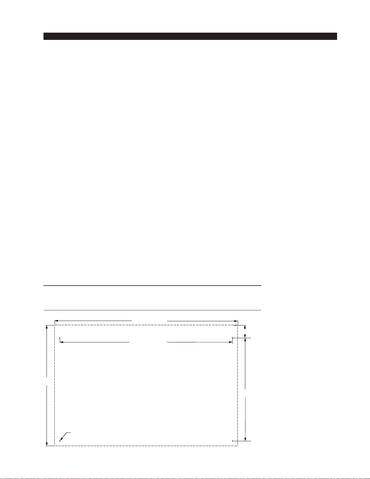
CountertopMounting
The D-70 digital audio console is designed for countertop mount-
ing.Consoleplacementshouldavoidproximitytoanyelectromagnetic
fields, such as large power transformers, motors, and fluorescent
lightingfixtures.If you willbesecuringthe consoletothecountertop,
youmaywanttopre-drillthemountingholes(seesketchfor 20and28
position frames below).
Settheconsole in place on the counter, and remove the screws that
hold down the first and the last modules in place (two per module).
Carefully remove those modules from the frame. Attach the console
mainframe to the counter top, using the holes provided in the bottom
of the chassis and screws appropriate to the counter material, and
reinstall the removed modules.
The console extends approximately 7 3/4” above the countertop at
the meterbridge. Also, the rear panel requires 3 1/2” of clearance
behind the console to open fully.
DonotconnecttheD-70consoletoitspowersupply(anddonot
connectthepowersupplytotheACpowerline)untilinstructedto
do so.
NOTE:Thisconsolecontains
static-sensitivedevices.Nor-
malprecautionsagainststatic
dischargeshouldbeobserved
when handling individual
modules.
NOTE: Dimensions shown
are for 20 position main-
frames; 28 position frames
dimensions are shown in pa-
rentheses().
D-70 / Aug 2000
19.900
28.488 (40.568)
17.000
D=.171"; use #8 screws
Dashed line is console outline 2.100
30.210 (42.29)

I N S T A L L A T I O N a nd P OWER
page 1 – 3
D-70 / Apr 2000
Modules and Rear Panels Layout
The D-70 console’s mainframe comes supplied with 12 or 20 input modules, a
control room module, a studio control module, and single and dual blank modules.
There can be optional modules: a superphone module, the two line select modules,
and a tape remote module. Each module type has it’s assigned slot (see drawing on
page 1-4).
The D-70 console also comes supplied with rear panels that are installed in the
following order (from right to left as viewed from the rear of the console): 12 or 20
any variation of MIC IN, LINE IN or DIG IN input panels, DIG IN or LINE IN panel
for EXT IN for switched meters, BLANK or optional CALLER panel, DIGITAL
OUT, ANALOG OUT, MONITOR1, MONITOR2, four BLANKS or optional
LINE SELECT panels, BLANK or TAPE REMOTE, and BLANK or optional EXT
SYNC panel. Rear panels layout see on the page 1-5.
Rear Panels Installation
To remove or install console’s rear panels you
must follow this procedure:
• Make sure the console is powered down.
• Open the meterbridge cover by removing the
two retaining screws on its rear lip.
• Open the meterbridge rear by removing the two
retaining screws on the upper lip. Then swing it
toward you until it rests in a fully opened position.
• Remove the shield panel’s tape (Figure 1),
being careful to avoid damage to the shield tape.
• Swing the shield panel to open (Figure 2).
• Disconnect the rear panel’s connectors.
• Remove the two phillips-head screws that hold
the rear panel in place (Figure 3).
• Unplug the rear panel’s card from the edge
connector by carefully pulling it up.
• Replace the rear panel, plugging in its edgecard
fingers to the appropriate motherboard edge con-
nector (Figure 2), and tighten down the two retain-
ing screws.
Make sure that you plug in the rear panel in its
appropriate slot!
• Replace the shield panel back reusing the
shielding tape.
• Close and secure the meterbridge rear and
cover.
Figure 1. Shield Panel.
Figure 3.
Rear Panels—Rear View.
D-70 / Feb 2002
Figure 2. Open Shield Panel.
Figure 4.
Rear Panels—Upper View

O
N
O
F
F
0
5
10
15
20
30
40
50
70
00
60
CUE
A
B
PGM AUD
AUX1 AUX 2
INPUT
ASSIGN
O
N
O
F
F
0
5
10
15
20
30
40
50
70
00
60
CUE
A
B
PGM AUD
AUX1 AUX 2
INPUT
ASSIGN
O
N
O
F
F
0
5
10
15
20
30
40
50
70
00
60
CUE
A
B
PGM AUD
AUX1 AUX 2
INPUT
ASSIGN
O
N
O
F
F
0
5
10
15
20
30
40
50
70
00
60
CUE
A
B
PGM AUD
AUX1 AUX 2
INPUT
ASSIGN
O
N
O
F
F
0
5
10
15
20
30
40
50
70
00
60
CUE
A
B
PGM AUD
AUX1 AUX 2
INPUT
ASSIGN
O
N
O
F
F
0
5
10
15
20
30
40
50
70
00
60
CUE
A
B
PGM AUD
AUX1 AUX 2
INPUT
ASSIGN
O
N
O
F
F
0
5
10
15
20
30
40
50
70
00
60
CUE
A
B
PGM AUD
AUX1 AUX 2
INPUT
ASSIGN
O
N
O
F
F
0
5
10
15
20
30
40
50
70
00
60
CUE
A
B
PGM AUD
AUX1 AUX 2
INPUT
ASSIGN
O
N
O
F
F
0
5
10
15
20
30
40
50
70
00
60
CUE
A
B
PGM AUD
AUX1 AUX 2
INPUT
ASSIGN
O
N
O
F
F
0
5
10
15
20
30
40
50
70
00
60
CUE
A
B
PGM AUD
AUX1 AUX 2
INPUT
ASSIGN
O
N
O
F
F
0
5
10
15
20
30
40
50
70
00
60
CUE
A
B
PGM AUD
AUX1 AUX 2
INPUT
ASSIGN
O
N
O
F
F
0
5
10
15
20
30
40
50
70
00
60
CUE
A
B
PGM AUD
AUX1 AUX 2
INPUT
ASSIGN
SOURCE
1
2
3
4
5
6
7
SOURCE
1
2
3
4
5
6
7
REMOTE
PLAY
REC
STOP
REW
FF
RTZ
TB
10 9
8
7
64
3
2
10
5
STUDIO
10 9
8
7
64
3
2
10
5
TB
SWITCHED
METERS
EXT 1
PGM AUD
AUX1 2AUX
SOURCE
EXT 2
AUD
EXT
AUX1
AUX2
CUE
EXT 1
10 9
8
7
64
3
2
10
5
CUE
10 9
8
7
64
3
2
10
5
HDPN
TIMER
10 9
8
7
64
3
2
10
5
CR
PGM AUD
AUX1 2AUX
SOURCE
EXT 2
S/S
RST
HOLD
AUTO
LOC
REM
0
5
10
15
20
30
40
50
70
00
60
CUE 1 CUE 2
PGM AUD
AUX1AUX 2
O
N
O
F
F
MXM
SOURCE
ASSIGN
CALLER
1 2
P
G
A
D
A
1
A
2
D-70 CONSOLE MODULES LAYOUT FOR 20 POSITION FRAME
NOTE: 28 POSITION FRAME CONSOLE
CONTAINS 8 MORE INPUT BLOCKS
THAT INSERT AT THE LEFT END OF
FRAME
D-70 / Aug 2000 page 1 - 4

D-70 REAR PANELS LAYOUT FOR 20 POSITION FRAME
NOTES:
1. SLOTS 1 THROUGH 12 CAN BE ANY VARIATIONS OF DIG IN,
LINE IN OR MIC IN PANELS.
2. SLOT 13 CAN BE DIG IN OR LINE IN PANELS.
THIS SLOT IS EXTERNAL INPUT FOR SWITCHED METERS.
3. SLOT 24 - OPTIONAL ESYN PANEL.
4. 28 POSITION FRAME CONTAINS 8 ADDITIONAL INPUT PANELS.
1314151617181920212223 12 11 8
BLANK
FIXED
7 6 5 4 3 2 110 924
EXT
SYNC
L
H
DIG
IN
SL
S
HLT
RT
L
S
H
L
S
H
L
S
H
LT
RT
L
S
H
OUT
LT
RT
L
S
H
L
S
H
L
S
H
LT
RT
LINE
SELECT
B
5
6
7
1
L
S
H
2
RT
L
S
H
L
S
H
L
S
HRT
3
L
S
H
4
RT
L
S
H
L
S
H
L
S
HRT
LINE
SELECT
A
LT
LT
LT
LT
HDPN
L
S
H
CUE
RT
L
S
H
L
S
H
L
S
HRT
OUT
L
S
H
TB
N.
CAIR
TALLY
TALLY
2
TALLY
3
O.
N.
C
O.
N.
C
O.
MONITOR
2
LT
LT
EX1
L
S
H
EX2
LT
RT
L
S
H
L
S
H
L
S
H
LT
RT
CR
L
S
H
ST
LT
RT
L
S
H
L
S
H
L
S
H
LT
RT
MONITOR
1ANALOG
OUT
PGM
L
S
H
AUD
LT
RT
L
S
H
L
S
H
L
S
H
LT
RT
L
S
HLT
RT
L
S
H
L
S
H
L
S
H
LT
RT
AUX
1
AUX
2
DIGITAL
OUT
PGM
L
S
H
AUD
L
S
H
L
S
H
L
S
H
AUX
1
AUX
2
L
S
H
IN
OUT
L
S
H
L
S
H
L
S
H
L
S
H
C
L
S
H
L
S
H
CALLER
IN
OUT
1
1
2
2
A
L
L
M
I
C
S
C
O
M
P
START
COM
STOP
MIX
MIX
CALLER
DIG IN
IN A
IN B
DIG
TALLY
C
B5V
S/S
OFF
STOP
C
OFF
START
ON
RDY
ON
RDY
L
S
H
L
S
H
+
+
+
+
+
+
LINE IN
IN A
L
S
H
IN B
DIG
TALLY
5V
S/S
OFF
STOP
OFF
START
ON
RDY
ON
RDY
LT
RT
L
S
H
L
S
H
L
S
H
LT
RT
C
B
C
+
+
+
+
+
+
LINE IN
IN A
L
S
H
IN B
DIG
TALLY
5V
S/S
OFF
STOP
OFF
START
ON
RDY
ON
RDY
LT
RT
L
S
H
L
S
H
L
S
H
LT
RT
C
B
C
+
+
+
+
+
+
DIG IN
IN A
IN B
DIG
TALLY
C
B5V
S/S
OFF
STOP
C
OFF
START
ON
RDY
ON
RDY
L
S
H
L
S
H
+
+
+
+
+
+
A
INS
DIG
TALLY
C
B5V
5V
DIG
DIG
ON
OFF
-ON
-OFF
TB/CR
CGH
L
S
H
L
S
H
L
S
H
L
S
H
B
IN
OUT
IN
C
C
T
L
Y
+
+
MIC IN
L
S
HLT
RT
L
S
H
L
S
H
L
S
H
LT
RT
L
S
H
OUT
LT
RT
L
S
H
L
S
H
L
S
H
LT
RT
LINE
SELECT
B
5
6
7
1
L
S
H
2
RT
L
S
H
L
S
H
L
S
HRT
3
L
S
H
4
RT
L
S
H
L
S
H
L
S
HRT
LINE
SELECT
A
LT
LT
LT
LT
LINE IN
IN A
L
S
H
IN B
DIG
TALLY
5V
S/S
OFF
STOP
OFF
START
ON
RDY
ON
RDY
LT
RT
L
S
H
L
S
H
L
S
H
LT
RT
C
B
C
+
+
+
+
+
+
LINE IN
IN A
L
S
H
IN B
DIG
TALLY
5V
S/S
OFF
STOP
OFF
START
ON
RDY
ON
RDY
LT
RT
L
S
H
L
S
H
L
S
H
LT
RT
C
B
C
+
+
+
+
+
+
LINE IN
IN A
L
S
H
IN B
DIG
TALLY
5V
S/S
OFF
STOP
OFF
START
ON
RDY
ON
RDY
LT
RT
L
S
H
L
S
H
L
S
H
LT
RT
C
B
C
+
+
+
+
+
+
LINE IN
IN A
L
S
H
IN B
DIG
TALLY
5V
S/S
OFF
STOP
OFF
START
ON
RDY
ON
RDY
LT
RT
L
S
H
L
S
H
L
S
H
LT
RT
C
B
C
+
+
+
+
+
+
DIG IN
IN A
IN B
DIG
TALLY
C
B5V
S/S
OFF
STOP
C
OFF
START
ON
RDY
ON
RDY
L
S
H
L
S
H
+
+
+
+
+
+
A
INS
DIG
TALLY
C
B5V
5V
DIG
DIG
ON
OFF
-ON
-OFF
TB/CR
CGH
L
S
H
L
S
H
L
S
H
L
S
H
B
IN
OUT
IN
C
C
T
L
Y
+
+
MIC IN
A
INS
DIG
TALLY
C
B5V
5V
DIG
DIG
ON
OFF
-ON
-OFF
TB/CR
CGH
L
S
H
L
S
H
L
S
H
L
S
H
B
IN
OUT
IN
C
C
T
L
Y
+
+
MIC IN
A
INS
DIG
TALLY
C
B5V
5V
DIG
DIG
ON
OFF
-ON
-OFF
TB/CR
CGH
L
S
H
L
S
H
L
S
H
L
S
H
B
IN
OUT
IN
C
C
T
L
Y
+
+
MIC IN
ADDITIONAL 8 PANELS
FOR 28 POSITION FRAME
INSERT HERE
TR
SW6
SW6
L6
L6
SW5
SW5
L5
L5
SW4
SW4
L4
L4
SW3
SW3
L3
L3
SW2
SW2
L2
L2
SW1
SW1
L1
L1
+
+
+
C
N.
O.
C
N.
O.
C
N.
O.
+
+
+
C
N.
O.
C
N.
O.
C
N.
O.
DC IN
RS-232
RS-485
D-70 / Aug 2000 page 1 - 5

INSTALLATION and POWER
page 1 – 6
D-70 / Apr 2000
CONSOL
E
2-TRACK
MULTI-TRACK
AC BREAKER
BOX
DEVICE 1
DEVICE 2
DEVICE N
CONSOLE POWER SUPPLY
CONTROL ROOM POWER AMP
STUDIO POWER AMP
OTHER
POWER COMPANY
EARTH GROUND
HEAVY
(#4 or #6)
COPPER
WIRE
HIGH POWER
EQUIPMENT RAC
K
COPPER ROD
SOIL
3-wire ground or separate wire run from chassis
EFFECTS RAC
K
MIC PANEL
GND
TYPICAL SYSTEM
GROUNDING SCHEME
etc.
3–5 ft.
Tie the console ground lug
terminal strip to the system
earthground. Tieeverypiece
of equipment in the entire
audio system to the console
ground lug terminal strip.
System Ground
The first step is to ground the console.
Note that as supplied from the factory, console rackmount power
supplycommon,audioground,andtheD-70mainframeareconnected
togetherattheconsole,butareNOTconnectedtoelectricalgroundand
the chassis of the power supply. Safety requirements dictate that a
positiveconnectionfromtheconsolemainframetoelectricalgroundbe
made in the completed installation. Use one of the grounding lugs on
the rear of the mainframe to establish your system ground. The
groundinglugterminalstripmaybefoundattherearoftheconsole,on
the rear frame panel, to the right if you are looking at the rear of the
console.
The system ground serves two important purposes:
(1) It provides a zero signal reference point for the entire audio system;
(2) It assures safety from electrical shock.
Thereexisttwotermsthatoneencountersinadiscussionofground:
(A)EARTHGROUND,whichisusuallyaheavycopperroddrivenintothe
soiladjacenttothebuilding(around6feetdown)oraconnectiontothecopper
water pipes leading into the building. Either is acceptable (unless, of course,
the water pipe is made of plastic).
D-70 / Aug 2003

INSTALLATION and POWER
page 1 – 7
D-70 / Apr 2000
(B) THE POWER COMPANY EARTH CONDUCTOR that enters the build-
ing at the power line breaker box; this conductor should be (and is often by code)
tiedtotheabove-mentioned earth ground atonepoint. ThispointistheSYSTEM
EARTH GROUND.
TIE THE CONSOLE GROUND LUG TERMINAL STRIP TO THE
SYSTEMEARTHGROUND. TIEEVERYPIECEOFEQUIPMENTIN
THE ENTIRE AUDIO SYSTEM TO THE CONSOLE GROUND LUG
TERMINAL STRIP. If the system earth ground point is inaccessible, tie
the console ground terminal strip to the power company earth conductor
at the main breaker box (see drawing "Typical Grounding Scheme" on
previous page).
Each piece of equipment should be connected by its own ground wire
(usually the round third pin on the AC cord). This means that every AC
outlet must have a separate conductor run to the console ground lug
terminal strip; the outlets cannot be daisy-chained as is normally encoun-
tered in commercial and residential AC systems. Any equipment not
supplied with 3-wire AC cables must have individual ground wires (16
gauge or larger) connected to their chassis grounds and then run to the
console ground lug terminal strip.
Further Grounding Details
Check all equipment to be absolutely certain that each unit is power
transformer isolated from the AC mains to prevent safety hazards.
It is assumed that in each piece of audio equipment the audio ground
and the chassis are tied together at some point. Any piece of equipment
lacking a grounded chassis is likely to be prone to interference problems.
Locateallunbalanced audioequipmentinthe samerackifpossible, to
minimize chassis ground potential differences. It may also be helpful to
insulateeachpieceofunbalancedequipmentfromitsmountingrailsinthe
rackbymeansofnylon10-32screwsandinsulatingwashersbetweenrails
and faceplates.
Once the system is properly grounded, proceed with the console
power supply installation and connection (next section).
Power Supply
TheD-70consoleispoweredbyaAudioartsModelSPS-16rackmount
power supply. This unit occupies two 19” wide rack spaces (total height
3-1/2”).Convectioncooled,itrequiresampleventilationspaceaboveand
below it. The SPS-16 generates a lot of heat in the course of normal
operation— donotmountheatsensitivedevicesinthesamerackcabinet.
Notethepowersupplyshouldbemountedinanequipmentrackwithin
fifteen feet of the console (but no closer than 3 feet). Avoid locating any
highgainequipment(suchasphonopreamps,taperecorders,etc.)toonear
the rackmount supplies, to avoid magnetic interference into that equip-
ment.
D-70 / Aug 2003

INSTALLATION and POWER
page 1 – 8
D-70 / Apr 2000
Thispowersupplycontainshighvoltagecircuitsthatarehazardousand
potentially harmful. Under no circumstances should the metal cover be
removed! If you have a problem with the power supply, the SPS-16 unit
must be returned to Audioarts for repair.
Once the supply is
rackmounted, it should be con-
nected to the console using the
factory supplied cable. The cable
is already attached and clamped
in place at the console end. The
free end has an 8-pin male con-
nector; you just need to connect
this end of the cable to the rear of
therackmountSPS-16powersup-
ply.Noteeachpowersupplyisfit-
ted with a 3-wire grounded AC
cordthatshouldbepluggedintoa
"clean"ACpowersource. Thatis,
an AC source that feeds only the
control room audio gear. This
source should be a separate feed
fromthose powering lighting, air-
conditioning, or any other non-
audio machinery. The third pin
ground wire of the AC source
shouldbetiedtothecentralsystem
ground point. Note that while the
ACpowercordgroundwiretermi-
nates at the power supply chassis,
it does NOT connect to the D-70 console common; the console itself must
be grounded separately. (See previous section, "System Ground".)
The power feed recom-
mended in the text is of-
teninstalledandreferred
to in studios as an “iso-
lated AC ground” outlet.
It is usually orange in
color.
D-70 / Aug 2003
Front view of the SPS-16
rackmount power supply
Rear view of the SPS-16
rackmount power supply
1
2
3
4
Audio
C
ommon
+ V
- V
+ Digital
PIN PIN
8-pin Connecto
r
Male
Power Supply End
9-pin Connecto
r
Female
Console End
6
7
8
9
Digital
C
ommon
+ Digital
Digital
C
ommon
Phantom
BLK
RED
BLU
YEL
GRN
ORG
BRN
VIO
PS Cable Pinout
6
8
7
4
2
5
3
1
BLK
RED
BLU
YEL
GRN
ORG
BRN
VIO
(Pin 5 - N/C)
Console
End Power Supply
End

INSTALLATION and POWER
page 1 – 9
D-70 / Apr 2000
Energizing
Assuming the D-70 console mainframe is properly placed and
grounded, and its SPS-16 power supply correctly rackmounted and
connectedtotheconsole,youmaynowenergizetheSPS-16rackmount
power supply by plugging it into the AC mains. The five LEDs on the
power supply front panel should light up to indicate the presence of
theirrespectivevoltages.Theconsole'sLEDmeterswillilluminateand
individual module switches will assume factory default settings.
Note: To de-energize the console, unplug the rackmount power
supply’s AC cord from the AC mains. Never de-energize the console
by disconnecting the cable that connects the console and power
supply together.
Once you have verified proper power-up, unplug the rackmount powerOnce you have verified proper power-up, unplug the rackmount power
Once you have verified proper power-up, unplug the rackmount powerOnce you have verified proper power-up, unplug the rackmount power
Once you have verified proper power-up, unplug the rackmount power
supply to de-energize the console. You may now proceed to wire upsupply to de-energize the console. You may now proceed to wire up
supply to de-energize the console. You may now proceed to wire upsupply to de-energize the console. You may now proceed to wire up
supply to de-energize the console. You may now proceed to wire up
audio and control connections.audio and control connections.
audio and control connections.audio and control connections.
audio and control connections.
Audio and Control Wiring
Every input and every output has its own dedicated six- or twelve-
conductor connector (mating plugs supplied). Now in-field wiring
changes are fast and easy, and of course rapid throubleshooting is an
obvious benefit. This system also avoids the conductor pinching and
stray strand shorting that plague screw terminals. Reliability and
maintenance are the keys here.
Connection Procedures
Assuppliedfromthefactory,theconsolerequiresnologicconnec-
tions to function. Therefore an orderly installation begins with the
audio wiring. Note this manual is organized by module type (inputs,
outputs,monitormodules,etc.);eachchaptercontainsdetailed wiring
instructions for its module type. Proceed through the manual, chapter
by chapter, until all modules have been wired to suit your particular
installation requirements. Once proper audio operation is verified, go
back to each individual chapter and proceed with control wiring.
Digital Audio Connections
CABLE-AllAES/EBUinputandoutputdigitalaudioconnections
are balanced and should be made using a high quality digital audio
cable.Besure toselectadigitalaudiocablewith anintegraldrainwire
of the same wire gauge (AWG) as the twisted pair. Typical AES/EBU
digitalaudiocablehasaverylowcharacteristiccapacitanceperft(pF/
ft),andanominalimpedanceof110Ω.Highqualitydigitalaudiocable
offers better signal transmission performance versus typical analog
audiocable,especiallyoverlongcableruns.Checkthecablemanufac-
tures data sheet to be sure the cable you plan to use will work in your
application.
D-70 / Aug 2003
Table of contents
Other AudioArts Engineering Recording Equipment manuals

AudioArts Engineering
AudioArts Engineering D-16 User manual

AudioArts Engineering
AudioArts Engineering D-76 User manual

AudioArts Engineering
AudioArts Engineering R-60 User manual

AudioArts Engineering
AudioArts Engineering R-5 User manual

AudioArts Engineering
AudioArts Engineering R-55 User manual

AudioArts Engineering
AudioArts Engineering D-75 User manual


