Harding MicroComm DXI MAI-625 User manual

MAI-625 Master Audio Interface
Document IM-MAI-625-`1.0 2012 Harding Instruments - Printed in Canada
INSTALLATION MicroCommDXI
INSTRUCTIONS
1Intent & Scope
This document describes the installation procedure for the MAI-625 Master Audio Interface.
2Description
The MAI-625 Master Audio Interface is a Voice over Internet Protocol (VoIP) device for DXL
intercom systems and is used to facilitate the integration of a variety of intercom master station
components into a console or control panel.
The MAI-625 provides three separate RJ-25 connectors in support of an SMK-126/136 Panel
Mount Handsfree Speaker/Microphone Kit, an HHK-136 Handset/Hookswitch Kit, and an
HSK-136 Headset Kit. These kits provide handsfree audio, a privacy handset, or a headset
interface, and can be installed in any combination desired. Please refer to their individual
datasheets for further information.
The MAI-625 also includes a line-level input and output to facilitate making audio connections
to an existing system. The line level output can also connect to an amplifier for driving
external powered speakers. A status input, and a DPDT control relay are also available. These
signals are provided on terminal blocks with the line-level output (also) brought out to a 3.5
mm stereo audio jack.
A combination of these audio devices can be used. If more than one audio/input device is connected to the MAI
the hookswitch and headset switch will determine which speaker receives audio and which microphone is active.
If the hookswitch is off hook the speaker audio is connected to the handset speaker and handset microphone
audio is connected to the microphone audio lines. If the hookswitch is on hook the speaker audio is connected to
either the headset or handsfree speaker depending on the state of the headset switch. If the headset switch is
closed (corresponding to having a headset jack plugged in) the headset microphone is active and the speaker
audio is connected to the headset. If the hookswitch is on hook and the headset switch is open then handsfree
operation is possible. Figure 1 describes the operation of the hookswitch and headset switch.
HEADSET
HANDS
FREE
HANDSET
HANDSET
ON
HOOK OFF
HOOK
CLOSED
OPEN
HEADSET SWITCH
HOOKSWITCH
Figure 1. Operation of Hookswitch and Headset Switches
MAI-625 Master Audio Interface
Page 2 Document IM-MAI-625-1.0
The MAI-625 has provisions for a line level output that can be used to drive speakers via an external amplifier.
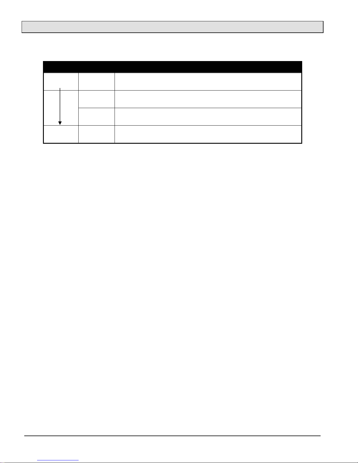
The following table summarizes the audio resource priorities
Priority Device Audio Resource
Highest Handset Input: Handset Microphone
Out
p
ut: Handset S
p
eaker
(
Line Out disabled
)
Headset Input: Headset Microphone
Out
p
ut: Headset S
p
eaker
(
Line Out disabled
)
Line Out Input: Handsfree Mic (Panel Mount Gooseneck or Flush Mic)
Out
p
ut: Line out
& Panel Mount M
y
lar S
p
eaker
Lowest Handsfree
Input: Handsfree Mic (Panel Mount Gooseneck or Flush Mic)
Out
p
ut: Panel Mount Handsfree S
p
eaker
Table 1: Audio Resource Priorities
Note when driving external speakers the panel mount handsfree speaker is not disabled when the line output is
active.
The MAI-625 has provisions for several press-to-talk (PTT) inputs. The PTT switches can be used to control the
audio direction of half duplex calls. The PTT inputs are available on the RJ-25 connectors
The MAI-625 can be software controlled so that the line level inputs and line level outputs can serve as a bridge
between a DXL system and an existing audio system.

MAI-625 Master Audio Interface
Document IM-MAI-625-1.0 Page 3
3Wall Mounted MAI-425 Master Audio Interface
The MAI-625 can be either wall mounted using the 0.15” diameter holes and #6 screws or mounted on a DIN rail
using the 4 holes for mating to a DIN railclip. (A 209-188 Mounting Foot for mounting on DIN Rail Wago 210
Series)
Status Output
Ethernet
Ethernet
with PoE
Headset
Handset
Speaker/Mic
Status Reset
Line Out
1
2
3
4
6
7
5
10
9
8
13
11
12
14
+
-
+
-
Line Out
Line In
+
-
Power +
-
NO 1
COM 1
NC 1
NO 1
COM 1
NC 1
Power
+-
MAI-625
MicroComm
Master Audio Interface
5.75"
6.00"
5.33"
4.12"
1.04"
Status In
2 ea 0.15" diameter
4 ea 0.143" diameter
for DIN rail clips
Figure 2. Mounting hole positions, for the MAI-425

MAI-625 Master Audio Interface
Page 4 Document IM-MAI-625-1.0
4Wiring Diagram for MAI-625
The following diagram shows the wiring required to connect up the Headset, Handset, and Handsfree
Speaker/Microphone kits to an MAI-625.
Status Output
Ethernet
Ethernet
with PoE
Headset
Handset
Speaker/Mic
Status Reset
Line Out
1
2
3
4
6
7
5
10
9
8
13
11
12
14
+
-
+
-
Line Out
LineIn
+
-
Power +
-
NO 1
COM 1
NC 1
NO 1
COM 1
NC 1
Power
+-
MAI-625
MicroComm
Master Audio Interface
Status In
PTT
VOLUME
Handsfree Speaker/Microphone Kit
SMK-126
PTT Footswitch
Headset
Handset
RJ-25
Junction Box
RJ-25
Junction Box
Headset Jack
Headset Plug
RJ-25 Male Plug
RJ-25 Male
Plug
RJ-25 Male
Plug
RJ-45 Male
Pug
ETHERNET SWITCH
RJ-45 Male
Plug
Handset/Hookswitch Kit
HHK-136
RJ-25 Male
Plug
Headset Kit
HSK-136
RJ-25 Male Plug
RJ-25 Male Plug
Figure 3. Wiring Diagram for MAI-625

MAI-625 Master Audio Interface
Document IM-MAI-625-1.0 Page 5
5Field Connection
5.1 Network Connections
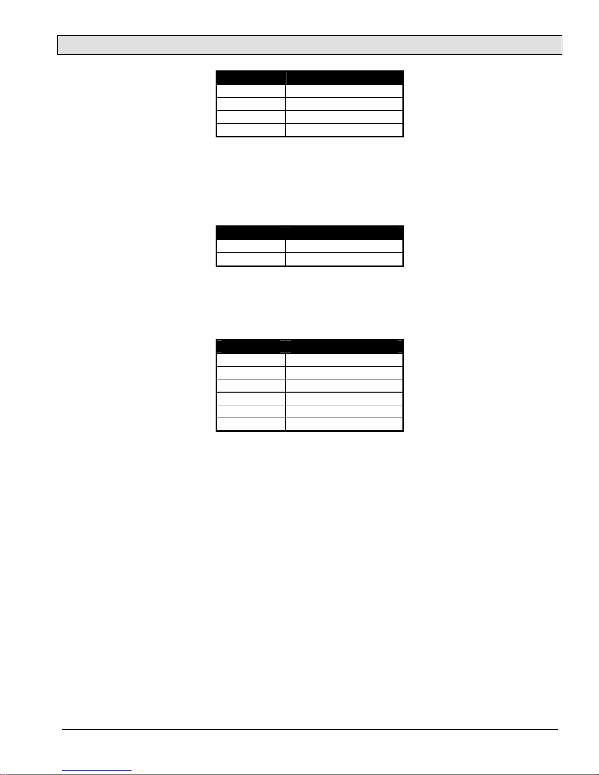
Although the PSE (Power Source Equipment) must use the pin pairs assigned to an endspan or midspan (not
both) the PD (Powered Device) must have the capability to accept power from either the endspan or midspan
device. The Ethernet RJ-45 includes both the network and power connections.
RJ-45 Pin Function
1 Tx+
2 Tx-
3 Rx+
4 48Vdc (SRC)
5 48Vdc (SRC)
6 Rx-
7 48Vdc (RETURN)
8 48Vdc (RETURN)
Table 2: RJ-45 Ethernet & PoE (Lower position)
The second RJ-45 includes only the network connections and is intended for the purpose of facilitating the
connection of another device.
RJ-45 Pin Function
1 Tx+
2 Tx-
3 Rx+
4 NC
5 NC
6 Rx-
7 NC
8 NC
Table 3: RJ-45 Ethernet (Upper Position)
5.2 Connections for SMK-126/136, HHK-136 and HSK-136 Kits
5.2.1 Handsfree Speaker/Microphone
The handsfree speaker and gooseneck (or flush mount) microphone with PTT connect via an RJ-25. The Speaker
Microphone Kit (SMK-136) is available to facilitate the installation.
RJ-25 Pin Function
1 Mic +
2 Push to Talk (PTT +)
3 Spk +
4 Spk -
5 Vol + (Potentiometer)
6 Mic -, PTT -, Vol -
Table 4: RJ-25 Handsfree Speaker/Microphone with PTT

MAI-625 Master Audio Interface
Page 6 Document IM-MAI-625-1.0
5.2.2 Handset Hookswitch
The handset speaker and microphone with hookswitch and PTT connect via an RJ-25. The Handset Hookswitch
Kit (HHK-136) is available to facilitate the installation.
RJ-25 Pin Function
1 Mic +
2 Push to Talk (PTT +)
3 Spk +
4 Spk -
5 HKSW +
6 Mic -, PTT -, HKSW - , (Gnd)
Table 5: RJ-25 Handset with PTT
5.2.3 Headset
The headset speaker and microphone with PTT connect via an RJ-25. The Headset Kit is available to facilitate the
installation.
RJ-25 Pin Function
1 Mic +
2 Push to Talk (PTT +)
3 Spk +
4 Spk -
5 Not used
6 Mic -, (PTT -)
Table 6: RJ-25 Headset with PTT
5.3 Other Connections
5.3.1 Line Output
A right angle 3.5mm stereo jack connects the line out with the mono output connected to both the left and right
speakers.
Jack Function
Tip Line Out +
Ring Line Out +
Sleeve Line Out -
Table 7: Line Output
5.3.2 Line Input/Output
The line input/output supports the potential audio bridging to an existing DXI system. The Line out is in parallel
with the 3.5mm stereo jack described previously.
MAI-625 Master Audio Interface
Document IM-MAI-625-1.0 Page 7
TB-04 Function
1 Line Out +
2 Line Out -
3 Line In +
4 Line In – (Gnd)
Table 8: Line Input/Output
5.3.3 Status Input
An unsupervised input is supported via a two pin terminal block. The status input is required for the audio
bridging function.
TB-02 Function
1 Input +
2 Input – (Gnd)
Table 9: Status Input
5.3.4 Status Output
The DPDT relay outputs are as follows.
TB-06 Function
1 NO
2 COM1
3 NC
4 NO
5 COM2
6 NC
Table 10: Status Relay Contacts
5.3.5 Auxiliary Power
A right angle 2.1mm barrel jack configured as center-positive is available in place of PoE.
5.3.6 Status Indicator
A right angle green LED for general status indication.
5.3.7 Earth Ground
A #6 self-tapping hole is available for the purpose of earth grounding the enclosure.
Table of contents


