AudioArts Engineering D-76 User manual

D-76
Digital Audio Console
Technical Manual
February 2015

D-76 / Feb 2015
D-76 Digital Audio Console Technical Manual
©2015 Audioarts®Engineering*
AUDIOARTS ENGINEERING
600 Industrial Drive
New Bern, North Carolina 28562
252-638-7000
*a division of Wheatstone Corporation

Read Me!
D-76 / Mar 2015D-76 / June 2015
Attention!
Federal Communications Commission (FCC) Compliance
Notice:
Radio Frequency Notice
NOTE: This equipment has been tested and found to comply with the
limits for a Class A digital device, pursuant to Part 15 of the FCC rules.
These limits are designed to provide reasonable protection against harmful
interference when the equipment is operated in a commercial environment.
This equipment generates, uses, and can radiate radio frequency energy and,
if not installed and used in accordance with the instruction manual, may cause
harmful interference to radio communications. Operation of this equipment
in a residential area is likely to cause harmful interference in which case the
user will be required to correct the interference at his own expense.
This is a Class A product. In a domestic environment,
this product may cause radio interference, in which case,
the user may be required to take appropriate measures.
This equipment must be installed and wired properly in order to assure
compliance with FCC regulations.
Caution!
Any modications not expressly approved in writing by
Wheatstone could void the user's authority to operate this equipment.

Read Me!
D-76 / Feb 2015
Attention!
This console contains static sensitive devices:
Normal precautions against static discharge should be observed when
handling individual modules. In particular, modules being packed for
shipping for return or repair must be packed in special static protection bags
before packaging. Damage caused by static discharge may not be covered
under warranty.
Replacing Modules in a Powered-up Console:
While in an emergency situation it is possible to remove and insert
modules on a powered-up console, Wheatstone does not recommend this
procedure. Whenever possible it is best to power down the console rst
before removing or replacing modules.
However, if you nd you must proceed with this operation, then be sure
to take the following precaution:
When re-inserting a module, take care to replug it squarely into
its mainframe connector socket, so all edgecard ngers make contact
simultaneously. In other words, the gold-plated bus connector ngers on the
bottom edge of the module's printed circuit board must be inserted squarely
(i.e., perpendicular) to the mating socket on the bottom pan of the console
mainframe. The intent is to prevent a situation where one of the module's
power pins makes signicant contact before the others. (Naturally, this
same precaution must be taken when using extenders.)
If the above instructions are followed the procedure should be routine;
if they are not, you could run the risk of damaging the console's logic chips.
Again, to avoid ANY possibility of this damage, whenever possible
we strongly recommend powering down the console before replacing any
modules.

Read Me!
D-76 / Feb 2015
IMPORTANT!
D-76 Audio Levels
General
All professional digital audio broadcast consoles manufactured by Wheatstone are hybrid in
nature. That is, they allow the user to connect both analog and digital domain sources and
provide both analog and digital outputs. While this approach allows for greater exibility
when interconnecting source and destination equipment, the user must be aware of what
levels to expect when applying, say, a digital input and measuring at an analog output.
Gain Structure
Broadcast consoles by design have various electronic stages at which the signal level may
be amplied or attenuated. The primary stages are the A-D converter input, channel fader,
DSP mixing and the bus output D-A converters. The sum of these gain stages is commonly
referred to as the console’s “gain structure.” Wheatstone consoles are factory calibrated for
0dB or “unity gain” when the input channel fader is set to nominal (-12dB).
The following is a stage by stage breakdown of a typical console’s gain stages:
Analog Input (A-D Converter)
• The ADC input circuit cards are designed so that a +4dBu input signal will yield
a -20dBFS digital output with the channel fader at nominal.
• An input gain adjust switch setting can be changed to increase the gain by 8dB
to allow for interfacing unbalanced equipment.
• Mic level preamps have trim pots for matching various microphone source levels
to the console’s normal +4dBu analog operating level.
DSP Gain
• Set in rmware for unity gain (-20dBFS input yields a -20dBFS output when the
input channel fader is set to nominal), digital attenuation may be applied on a
channel by channel basis via a dipswitch setting.
Analog Bus Output Gain (D-A Converter)
• • The analog output DAC circuits are designed so that a -20dBFS digital input
signal will yield a +4dBu analog output with the channel fader at nominal.

Read Me!
D-76 / Feb 2015
Audio Reference Levels
All consoles are fully factory calibrated and will comply with the following reference level:
-20dBFS digital = +4dBu analog = 0VU Note: 0dBu = .775v rms
+4dBu = 1.23v rms
These settings will provide a headroom of 20dB over the nominal input signal of +4dBu
analog, or -20dBFS digital.
Note that due to the lack of level standards in the digital domain, headroom available for
digital sources will be entirely dependant on the source. In fact, CD's are frequently made
with less than 1dB of digital headroom, and any boosting of digital CD levels in the console
by moving the fader up above the nominal can result in overload distortion for that channel.
For this reason, a dipswitch allows for digital attenuation on a fader by fader basis; digital
sources can be conveniently attenuated this way to guard against digital overload caused by
not enough headroom on the digital source. Since the D-76 console meters are true digital
reading meters, they will always show the console's digital levels, and whether there are any
"overs" in the signal. By pressing a channel's "CUE" button, the switched meters will show
the digital level of that channel's source, as modied by the dipswitch setting. By using the
program and watching these meters, the amount of attenuation can be adjusted to meet your
headroom requirements.
Typical Input Levels
Mic Inputs Nominal = -50dBm, 150Ω Maximum = -26dBm
Analog Inputs Nominal = +4dBu Maximum = +24dBu
Digital Inputs Nominal = -20dBFS Maximum = 0dBFS
Important

page Contents – 1
D-76 / Feb 2015
CONTENTS
Chapter 1 - Installation and Power
Chapter 2 - Quad Mic Preamp
D-76 Technical Manual
Table of Contents
Console Overview .........................................................................1-2
Unpacking The Console................................................................1-3
Countertop Mounting ....................................................................1-3
System Ground..............................................................................1-4
The First Step Is To Ground The Console ..................................................................1-4
Further Grounding Details ..........................................................................................1-5
Power Supply.................................................................................1-6
Energizing...................................................................................................................1-7
Audio and Control Wiring .............................................................1-7
Digital Audio Connections..........................................................................................1-7
Unbalanced Connections (analog audio) ...................................................................1-8
Modules Layout .............................................................................1-8
Input Daughter Cards Installation................................................1-9
D-76-12 Console Modules Layout Drawing................................1-10
D-76-20 Console Modules Layout Drawing................................1-11
Overview.........................................................................................2-2
Internal Programming Options.....................................................2-3
Phantom Power..........................................................................................................2-3
Hook-Ups........................................................................................2-3
Audio Input Connections............................................................................................2-3
Audio Output Connections.........................................................................................2-3
Power Connections ....................................................................................................2-4
Plug Terminal/ RJ-45 Pinout Drawing..........................................2-5
Installing The Optional Second QMP4-76 Mic Preamp ..............2-6

page Contents – 2
D-76 / Feb 2015
CONTENTS
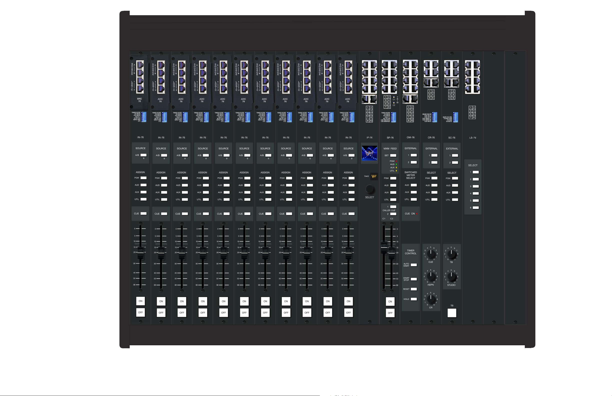
Module Overview...........................................................................3-2
Internal Programming Options.....................................................3-3
Mutes..........................................................................................................................3-3
Tallies..........................................................................................................................3-3
Timer Restart..............................................................................................................3-3
Talkback .....................................................................................................................3-3
Attenuation .................................................................................................................3-4
EFS - European Fader Start .......................................................................................3-4
UTIL Pre-Fade/Pre-On Defeat....................................................................................3-4
B Source Logic Options .............................................................................................3-5
External AES Sync Input ............................................................................................3-5
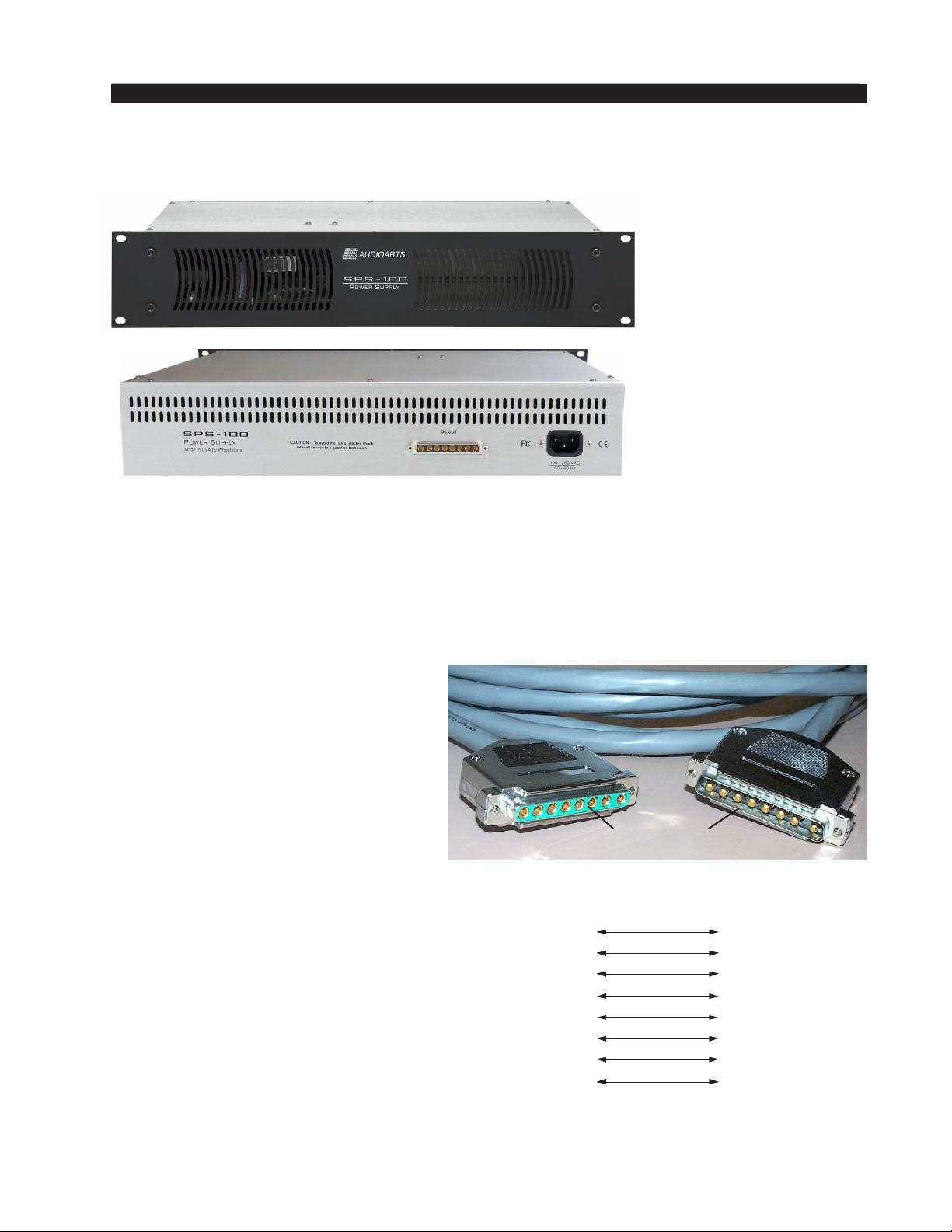
Hook-Ups........................................................................................3-7
Analog Audio Connections (ADC-76) .........................................................................3-7
Digital Audio Connections (SRC-76) ..........................................................................3-7
Logic Connections .....................................................................................................3-7
Remote ON/OFF.....................................................................................................3-7
Cough.....................................................................................................................3-8
External Start/Stop.................................................................................................3-8
Ready .....................................................................................................................3-8
Talkback to Control Room......................................................................................3-8
On Tally...................................................................................................................3-8
B Tally .....................................................................................................................3-9
RJ-45 Connector Pinout Drawing ...............................................3-10
IN-76 Stereo Line Input Module Signal Flow Diagram ..............3-11
Module Overview...........................................................................4-2
Internal Programming Options.....................................................4-3
Sampling Frequency for Console Outputs .................................4-3
Hook-Ups........................................................................................4-4
RJ-45 Connector Pinout Drawing ................................................4-5
Output Module Signal Flow Diagram...........................................4-6
Module Overview...........................................................................5-2
Internal Programming Options.....................................................5-3
Cue Interrupt ..............................................................................................................5-3
CR/Cue Mute..............................................................................................................5-3
On-Air Tally Follows Program.....................................................................................5-3
Hook-Ups........................................................................................5-4
RJ-45 Connector Pinout Drawing ................................................5-5
Control Room Module Signal Flow Diagram...............................5-6
Chapter 4 - Output Module (OM-76)
Chapter 5 - Control Room Module (CR-76)
Chapter 3 - Stereo Line Input (IN-76)

page Contents – 3
D-76 / Feb 2015
CONTENTS
Module Overview...........................................................................6-2
Internal Programming Options.....................................................6-3
External Talkback Mute/Dim ......................................................................................6-3
Studio Dim..................................................................................................................6-3
Studio Pre Mute .........................................................................................................6-3
Hook-Ups........................................................................................6-4
RJ-45 Connector Pinout Drawing ................................................6-5
Studio Control Module Signal Flow Diagram..............................6-6
Module Overview...........................................................................7-2
Caller Set-Ups............................................................................................................7-2
Automatic Features ....................................................................................................7-3
Inputs and Outputs.....................................................................................................7-3
Internal Programming Options.....................................................7-3
Cue Pre/Post ..............................................................................................................7-3
Mutes..........................................................................................................................7-3
Timer Restart..............................................................................................................7-4
Tallies..........................................................................................................................7-4
Cue Dropout...............................................................................................................7-4
External Input .............................................................................................................7-4
Gain Trimpots .............................................................................................................7-4
Hook-Ups........................................................................................7-5
External Start/Stop.....................................................................................................3-6
RJ-45 Connector Pinout Drawing ................................................7-6
Superphone Module Signal Flow Diagram..................................7-7
Module Overview...........................................................................8-2
Internal Programming Options.....................................................8-2
Hook-Ups .......................................................................................8-3
RJ-45 Connector Pinout Drawing ................................................8-4
Line Select Module Signal Flow Diagram....................................8-5
Module Overview...........................................................................9-2
Adding IP-76 to the Peripheral Devices Tab ...............................9-2
Chapter 6 - Studio Control Module (SC-76)
Chapter 7 - Superphone Module (SP-76) - optional
Chapter 8 - Line Select Module (LS-76) - optional
Chapter 9 - Network Module (IP-76) - optional
D-76 / May 2016

page Contents – 4
D-76 / Feb 2015
CONTENTS
Chapter 10 - Meterbridge
WheatNet-IP IP76 GUI....................................................................9-5
IP76 GUI Menu...........................................................................................................9-6
File..........................................................................................................................9-6
View........................................................................................................................9-6
WheatNet-IP System..............................................................................................9-6
Hardware ................................................................................................................9-8
Help ........................................................................................................................9-9
Device Properties ......................................................................................................9-10
Blades Tab.............................................................................................................9-10
Miscellaneous Tab.................................................................................................9-10
3rd Party Signal Name Prex ............................................................................9-10
Display Brightness.............................................................................................9-11
I/O Connections............................................................................9-12
Source Selection ..........................................................................9-12
OLED Display................................................................................9-12
IP-76 Menus...................................................................................9-13
Internal Programming Functions ................................................9-13
Hook-Ups.......................................................................................9-13
Audio Connection......................................................................................................9-13
Logic Connection ......................................................................................................9-14
Ethernet Interface......................................................................................................9-14
Typical Ethernet Cable ..........................................................................................9-14
RJ-45 Connector Pinout Drawing .............................................................................9-15
Overview........................................................................................10-2
Digital Timer..................................................................................10-2
Console Clock...............................................................................10-3
Setting The Time .......................................................................................................10-3
Capacitor Backup .....................................................................................................10-3
Operational Modes....................................................................................................10-3
24 Hour Mode .......................................................................................................10-3
External Sync ........................................................................................................10-3
Dim ........................................................................................................................10-4
Replacement Parts List.................................................................A-2
Appendix

page 1 – 1
D-76 / Feb 2015
INSTALLATION AND POWER
Installation and Power
Console Overview .........................................................................1-2
Unpacking The Console................................................................1-3
Countertop Mounting ....................................................................1-3
System Ground..............................................................................1-4
The First Step Is To Ground The Console ..................................................................1-4
Further Grounding Details ..........................................................................................1-5
Power Supply.................................................................................1-6
Energizing...................................................................................................................1-7
Audio and Control Wiring .............................................................1-7
Digital Audio Connections..........................................................................................1-7
Unbalanced Connections (analog audio) ...................................................................1-8
Modules Layout .............................................................................1-8
Input Daughter Cards Installation................................................1-9
D-76-12 Console Modules Layout Drawing................................1-10
D-76-20 Console Modules Layout Drawing................................1-11
Chapter Contents

page 1 – 2
D-76 / Feb 2015
INSTALLATION AND POWER
D-76 / Jan 2016
Installation and Power
Console Overview
The D-76 is a tabletop, modular console available in a 12-channel or 18-channel frame.
Sporting a sleek new prole, the new D-76 comes standard with sample rate conversion,
ample mic preamps, plenty of stereo busses, and a comprehensive monitor section that
provides separate feeds to control room/headphone and studio monitor outputs — plus
headphone jack and built-in cue speaker. Optional WheatNet-IP compatibility extends
its reach outside the studio and opens it to unlimited sources from virtually anywhere.
The D-76 has four stereo busses, dual-domain outputs, sample rate conversion on all
digital inputs, and interchangeable input module daughter cards for easy analog-to-digital
conversion in the eld. Its modern design features backlit controls and meterbridge with
full-scale, bargraph digital peak plus VU metering and automatic timer and clock.
Individual plug-in modules make D-76 installation and service a breeze. The D-76
can be ordered with an optional superphone module, which supports two callers. It can
also be ordered with an optional IP-76 plug-in module for interfacing to the WheatNet-IP
Intelligent Network.
This console has everything that the industry has come to expect of an Audioarts
console – like rock solid reliability and ease of use – but is laid out in a sleek new design
that is both affordable and practical for the modern radio station.

page 1 – 3
D-76 / Feb 2015
INSTALLATION AND POWER
D-76 / Jan 2016
NOTE: This console
contains static-sensitive
devices. Normal pre-
cautions against static
discharge should be ob-
served when handling
individual modules.
Unpacking The Console
The D‑76 console is shipped as two packages. One carton contains the console and
technical documentation; and the other contains the rackmount power supply, connecting
cable, and connector kit.
Countertop Mounting
The D‑76 audio console is designed for countertop mounting. Console
placement should avoid proximity to any electromagnetic elds, such as
large power transformers, motors, and uorescent lighting xtures. If you
will be securing the console to the counter top, you may want to pre‑drill
the mounting holes (see sketch below).
Set the console in place on the counter, and remove the screws that hold
down the rst and the last modules in place (two per module). Carefully
remove those modules from the frame.Attach the console mainframe to the
counter top, using the holes provided in the bottom of the chassis and screws
appropriate to the counter material, and reinstall the removed modules.
The console extends approximately 7‑3/16" above the countertop at
the meterbridge. The hinged meterbridge will require 12‑1/2" above the
countertop surface and 5" behind the rear meterbridge to open freely.
Do not connect the D‑76 console to its power supply (and do not
connect the power supply to theAC power line) until instructed to do so.
6-15/16"
7-3/16"
WITHOUT FEET
1-1/2"
37-3 /4" D-76-20 (25-3/ 4" D- 76-12)
40-3 /4" D-76-20 (28-3/ 4" D- 76-12)
42 -3/8" D-76-20 (30- 1/4" D-76-12)
4 HOLES, D= 3/ 16"
USE #8 SCREWS TO ATTACH TO COUNTER
17-3/16"
5/8"
19-7/16"
2-1/8"
23-5/16"

page 1 – 4
D-76 / Feb 2015
INSTALLATION AND POWER
Tie the console ground lug
terminal strip to the system
earth ground. Tie every piece
of equipment in the entire
audio system to the console
ground lug terminal strip.
System Ground
The First Step Is To Ground The Console
Note that as supplied from the factory, console rackmount power supply common,
audio ground, and the D-76 mainframe are connected together at the console, but are NOT
connected to electrical ground and the chassis of the power supply. Safety requirements
dictate that a positive connection from the console mainframe to electrical ground be
made in the completed installation. Use the grounding lug on the rear of the mainframe
to establish your system ground. The grounding lug may be found at the rear of the
console, on the rear frame panel, to the left if you are looking at the rear of the console.
The system ground serves two important purposes:
(1) It provides a zero signal reference point for the entire audio system;
(2) It assures safety from electrical shock.
There exist two terms that one encounters in a discussion of ground:
(A) EARTH GROUND, which is usually a heavy copper rod driven into the soil adjacent to the
building (around 6 feet down) or a connection to the copper water pipes leading into the building.
Either is acceptable (unless, of course, the water pipe is made of plastic).
(B) THE POWER COMPANY EARTH CONDUCTOR that enters the building at the power
line breaker box; this conductor should be (and is often by code) tied to the above-mentioned earth
ground at one point. This point is the SYSTEM EARTH GROUND.
CONSOLE
2-TRACK
MULTI-TRACK
AC BREAKER
BOX
DEVICE 1
DEVICE 2
DEVICE N
CONSOLE POWER SUPPLY
CONTROL ROOM POWER AMP
STUDIO POWER AMP
OTHER
POWER COMPANY
EARTH GROUND
HEAVY
(#4 or #6)
COPPER
WIRE
HIGH POWER
EQUIPMENT RACK
COPPER ROD
SOIL
3-wire ground or separate wire run from chassis
EFFECTS RACK
MIC PANEL
GND
TYPICAL SYSTEM
GROUNDING SCHEME
etc.
3–5 ft.

page 1 – 5
D-76 / Feb 2015
INSTALLATION AND POWER
TIE THE CONSOLE GROUND LUG TO THE SYSTEM EARTH GROUND.
TIE EVERY PIECE OF EQUIPMENT IN THE ENTIRE AUDIO SYSTEM TO THE
CONSOLE GROUND LUG. If the system earth ground point is inaccessible, tie the
console ground lug to the power company earth conductor at the main breaker box
(see drawing “Typical Grounding Scheme” on previous page).
Each piece of equipment should be connected by its own ground wire (usually
the round third pin on the AC cord). This means that every AC outlet must have a
separate conductor run to the console ground lug; the outlets cannot be daisy-chained
as is normally encountered in commercial and residential AC systems. Any equipment
not supplied with 3-wire AC cables must have individual ground wires (16 gauge
or larger) connected to their chassis grounds and then run to the console ground lug
terminal strip.
Further Grounding Details
Check all equipment to be absolutely certain that each unit is power transformer
isolated from the AC mains to prevent safety hazards.
It is assumed that in each piece of audio equipment the audio ground and the chassis
are tied together at some point. Any piece of equipment lacking a grounded chassis
is likely to be prone to interference problems.
Locate all unbalanced audio equipment in the same rack if possible, to minimize
chassis ground potential differences. It may also be helpful to insulate each piece of
unbalanced equipment from its mounting rails in the rack by means of nylon 10-32
screws and insulating washers between rails and faceplates.
Once the system is properly grounded, proceed with the console power supply
installation and connection (next section).

page 1 – 6
D-76 / Feb 2015
INSTALLATION AND POWER
Power Supply
Front view of the SPS-100
rackmount power supply
Rear view of the SPS-100
rackmount power supply
Console
End
Power Supply
End
1
2
3
4
Phantom
Digital
C
ommon
Digital
C
ommon
+ Digital
NIPNIP
8-pin Connector
Male
Power Supply End
8-pin Connector
Female
Console End
5
6
7
8
+ Digital
Audio
C
ommon
- V
+ V
VIO
GRN
BRN
WHT
ORG
BLK
BLU
RED
PS Cable Pinou
t
1
2
3
4
5
6
7
8
VIO
GRN
BRN
WHT
ORG
BLK
BLU
RED
Note the power supply should be
mounted in an equipment rack within
fteen feet of the console (but no closer
than 3 feet).Avoid locating any high gain
equipment (such as phono preamps, tape
recorders, etc.) too near the rackmount
supplies, to avoid magnetic interference
into that equipment.
Once the supply is rackmounted, it
should be connected to the console using
the factory supplied cable.The cable has
two different types of connectors on it:
an 8-pin female connector that connects
to the console’s power supply connector,
and an 8-pin male connector that plugs
into the rear of the rackmount SPS-100
power supply. The console’s power
supply connector is located at the rear
of the console, toward the left end of the
meterbridge bottom pan when viewed
from the rear of the console.
The D-76 console is powered by an Audioarts Model SPS-100 rackmount power
supply. This unit occupies two 19" wide rack spaces (total height 3-1/2"). Convection
cooled, it requires ample ventilation space above and below it. The SPS-100 generates
heat in the course of normal operation — do not mount heat sensitive devices in the
same rack cabinet.

page 1 – 7
D-76 / Feb 2015
INSTALLATION AND POWER
Note that the power supply is tted with a 3-wire grounded AC cord
that should be plugged into a “clean” AC power source, that is, an AC
source that feeds only the control room audio gear. This source should
be a separate feed from those powering lighting, air-conditioning, or any
other non-audio machinery. The third pin ground wire of the AC source
should be tied to the central system ground point.
The power feed recom-
mended in the text is often
installed and referred to in
studios as an “isolated AC
ground” outlet. It is usually
orange in color.
Energizing
Assuming the D-76 console mainframe is properly placed and grounded, and its
SPS-100 power supply correctly rackmounted and connected to the console, you may
now energize the power supply by plugging it into the AC mains.
Note: To de-energize the console, unplug the rackmount power supply’s AC cord
from the AC mains. Never de-energize the console by disconnecting the cable that
connects the console and power supply together.
Once you have veried proper power-up, unplug the rackmount power supply
to de-energize the console. You may now proceed to wire up audio and control
connections.
Audio and Control Wiring
Audio I/O and control connections to the D-76 console are made via RJ-45 connectors,
and 12-pin plug terminal.
Digital Audio Connections
CABLE – All AES/EBU input and output digital audio connections are balanced
and should be made using a high quality digital audio cable. Be sure to select a digital
audio cable with an integral drain wire of the same wire gauge (AWG) as the twisted
pair. Typical AES/EBU digital audio cable has a very low characteristic capacitance per
ft (pF/ft), and a nominal impedance of 110ohm. High quality digital audio cable offers
better signal transmission performance versus typical analog audio cable, especially
over long cable runs. Check the cable manufacturer’s data sheet to be sure the cable
you plan to use will work in your application.
CONNECTORS – All AES/EBU connections are made with RJ-45 connectors.
SPDIF INPUTS – The SPDIF (Sony/Phillips Digital Interface) or “consumer”
digital audio interface is a two wire unbalanced signal typically on a single RCA style
connector. We recommend using shielded twisted pair cables for these connections.
Wire the SPDIF center conductor (HOT) to the SRC-76 “HI” input pin using one wire
of the pair and wire the SPDIF shell (ground) to the SRC-76 “LO” input pin with the
other wire of the pair. Connect the cable’s shield to the SRC-76 “SH” pin, leaving the
shield oating (that is, not connected) at the SPDIF end.
The SRC-76 digital input audio card is provided with 110 ohm / 75 ohm switches
on the A and B inputs to allow impedance matching with 75 ohm sources.

page 1 – 8
D-76 / Feb 2015
INSTALLATION AND POWER
D-76 / Jan 2016
Unbalanced Connections (analog audio)
ANALOG INPUTS – Wire to the console with typical shielded two conductor cable
(like Belden 9451), just as if you were connecting a balanced source. At the unbalanced
source machine’s output, connect the black wire (LO) to the shield.
ANALOG OUTPUTS – All of the D‑76 console’s line level analog outputs are
electronically balanced, low impedance, outputs, expecting a minimum load of 600ohms.
The outputs are balanced but are not oating, and therefore should only be connected
to external equipment having balances inputs.
Modules Layout
The D‑76 console’s mainframe can accomodate up to 21 (for 27 pos. frame) or 13 (for
19 pos. frame) input modules along with an output module, a control room module,
and a studio control module. Each module type has its assigned slot (see drawings on
pages 1‑10 and 1‑11). To handle mic level inputs, a quad mic preamp is included. Also
there can be optional modules: a superphone, a second quad mic preamp, a line select,
and a network. Modules must be placed in the slots indicated on the module layout
drawings that follow.

page 1 – 9
D-76 / Feb 2015
INSTALLATION AND POWER
Input Daughter Cards Installation
The console’s two different types of input daughter
cards (Figure 1) are shipped in a separate package, as
specied in your order:
• ANALOG ADC-76 (W#011228) daughter card;
• DIGITAL SRC-76 (W#011229) daughter card.
These are used to congure the inputs of the console
to match the different types of signal sources (analog in,
or digital in).
To install console’s daughter cards you must follow
this procedure:
• Make sure the console is powered down.
• Open the meterbridge by simply swinging it up
and back until it rests in a fully opened position
(Figure 2).
• Plug in the daughter card’s edgecard ngers to
the appropriate IN-76 edge connector (Figure 3),
and tighten it down with the two supplied Phillips
serrated panhead screws (included in the console’s
connector kit).
Figure 1. Two types of input daughter cards.
Figure 3. Module edge connector.Figure 2. Open the meterbridge.
Note: To provide a better ground contact, tighten down the serrated screws, then unscrew
them a little bit and tighten again. This procedure will remove paint from the face of
the daughter card under the screw head and provide a better metal surface contact.
• Close the meterbridge.
NOTE regarding the SRC-76 digital input daughter card: The SRC-76 has two slide
switches that are used to toggle the digital input impedance between 110 ohms (for AES
inputs) and 75 ohms (for SPDIF inputs). SW1 affects the A input and SW2 affects the B
input. Flip the switch to the ON position for a SPDIF input or to the OFF position for an
AES input. In addition to using the switch, the input must be wired correctly – see Digital
Audio Connections on page 1-7 and 1-8.

NOTE: 1. CONsOlE CaN aCCOmmOdaTE up TO 13 iNpuT mOdulEs, Or 12 iNpuT mOdulEs plus ONE supErphONE mOdulE, Or 11 iNpuTs plus supErphONE aNd NETwOrk mOdulEs.
2. masTEr OuTpuT, CONTrOl rOOm, sTudiO CONTrOl aNd OpTiONal supErphONE aNd NETwOrk mOdulEs havE ThEir dEdiCaTEd slOTs (as shOwN).
3. lasT ThrEE slOTs aT ThE righT ENd Of ThE framE shOuld bE usEd fOr OpTiONal liNE sElECT mOdulE.
page 1 – 10
D-76-12 CONSOLE MODULES LAYOUT
D-76 / Jan 2016
Table of contents
Other AudioArts Engineering Recording Equipment manuals

AudioArts Engineering
AudioArts Engineering D-75 User manual

AudioArts Engineering
AudioArts Engineering R-55 User manual

AudioArts Engineering
AudioArts Engineering D-70 User manual

AudioArts Engineering
AudioArts Engineering R-60 User manual

AudioArts Engineering
AudioArts Engineering R-5 User manual

AudioArts Engineering
AudioArts Engineering D-16 User manual
Popular Recording Equipment manuals by other brands

Littlite
Littlite MIDAS Series Configuration manual

Extron electronics
Extron electronics VersaTools MTP DA4 Setup guide

Adeunis RF
Adeunis RF EU868 LoRaWAN Technical reference manual

Digigram
Digigram IQOYA X/LINK Series user manual

Pepperl+Fuchs
Pepperl+Fuchs IDENTControl IC-KP-B5-V23 manual

Roland
Roland RA-50 owner's manual