AudioArts Engineering D-16 User manual
D-16
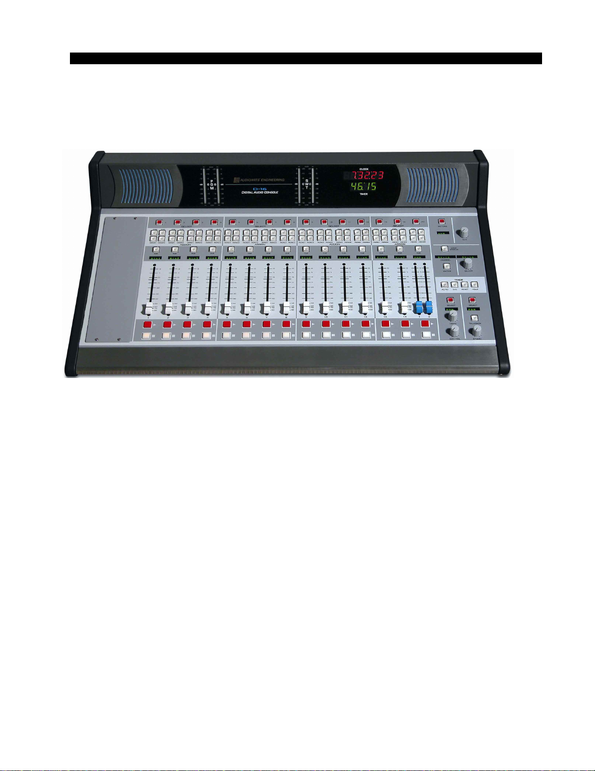
Digital Audio Console
TECHNICAL MANUAL
February 2003

D-16 Digital Audio Console Technical Manual - 1st EditionD-16 Digital Audio Console Technical Manual - 1st Edition
D-16 Digital Audio Console Technical Manual - 1st EditionD-16 Digital Audio Console Technical Manual - 1st Edition
D-16 Digital Audio Console Technical Manual - 1st Edition
©2003 Audioarts®Engineering*
AUDIOARTS ENGINEERING
600 Industrial Drive
New Bern, North Carolina 28562
252-638-7000
*a division of Wheatstone Corporation
D-16/ Feb 2003
AA
AA
ATTENTIONTTENTION
TTENTIONTTENTION
TTENTION
RR
RR
READEAD
EADEAD
EAD MM
MM
M
EE
EE
E!!
!!
!
D-16 / July 2003
Attention!
FF
FF
Federal Communications Commission (FCC)ederal Communications Commission (FCC)
ederal Communications Commission (FCC)ederal Communications Commission (FCC)
ederal Communications Commission (FCC)
Compliance Notice:Compliance Notice:
Compliance Notice:Compliance Notice:
Compliance Notice:
Radio FRadio F
Radio FRadio F
Radio Frequency Noticerequency Notice
requency Noticerequency Notice
requency Notice
NOTE:NOTE:
NOTE:NOTE:
NOTE: This equipment has been tested and found to comply with the
limits for a Class A digital device, pursuant to Part 15 of the FCC rules. These
limits are designed to provide reasonable protection against harmful
interference when the equipment is operated in a commercial environment.
This equipment, generates, uses and can radiate radio frequency energy
and, if not installed and used in accordance with the instruction manual,
may cause harmful interference to radio communications. Operation of this
equipment in a residential area is likely to cause harmful interference in
which case the user will be required to correct the interference at his own
expense.
!
This is Class A product. In a domestic environment,This is Class A product. In a domestic environment,
This is Class A product. In a domestic environment,This is Class A product. In a domestic environment,
This is Class A product. In a domestic environment,
this product may cause radio interference, in which case,this product may cause radio interference, in which case,
this product may cause radio interference, in which case,this product may cause radio interference, in which case,
this product may cause radio interference, in which case,
the user may be required to take appropriate measures.the user may be required to take appropriate measures.
the user may be required to take appropriate measures.the user may be required to take appropriate measures.
the user may be required to take appropriate measures.
This equipment must be installed and wired properly in order to assure
compliance with FCC regulations.
Caution!Caution!
Caution!Caution!
Caution!
Any modifications not expressly approved in writing byAny modifications not expressly approved in writing by
Any modifications not expressly approved in writing byAny modifications not expressly approved in writing by
Any modifications not expressly approved in writing by
Audioarts could void the user's authority to operate this equipment.Audioarts could void the user's authority to operate this equipment.
Audioarts could void the user's authority to operate this equipment.Audioarts could void the user's authority to operate this equipment.
Audioarts could void the user's authority to operate this equipment.

page Contents – 1
D-16 / Feb 2003
CONTENTS
D-16 Technical Manual
Table of Contents
Chapter 1 – Installation and Power
Unpacking the Console ................................................................1-2
CountertopMounting....................................................................1-2
System Ground .............................................................................1-3
Power Supply ................................................................................1-5
Failsafe Dual Redundant Supply.............................................................................. 1-6
Energizing ................................................................................................................. 1-6
Audio and Control Wiring.............................................................1-7
ConnectionProcedures ............................................................................................ 1-7
Digital Audio Connections ........................................................................................ 1-7
Unbalanced Connections (analog audio) ................................................................. 1-8
Installation Tip........................................................................................................... 1-8
Hand Crimp Tool Wiring Insrtuctions .........................................1-9
Chapter 2 – Console Features
Overview ........................................................................................2-2
Inputs .............................................................................................2-3
Analog Mono Mic Level Inputs ................................................................................. 2-3
Analog Stereo Line Level Inputs .............................................................................. 2-3
Digital Stereo Line Level Inputs................................................................................ 2-3
Producer Talkback Input........................................................................................... 2-3
Sources ..........................................................................................2-3
Faders ............................................................................................2-4
Outputs ..........................................................................................2-4
Mutes and Tallies ..........................................................................2-4
Other Features...............................................................................2-5
Console Layout Drawing ..............................................................2-6
D-16 / Jul 2003

page Contents – 2
D-16 / Feb 2003
CONTENTS
Chapter 3 – Fader Section
Overview ........................................................................................3-2
Hook-ups........................................................................................3-3
Microphone Inputs ......................................................................3-3
Stereo Line Analog Inputs..........................................................3-3
DB-25 “Line In 1-4” Connector ............................................................................. 3-3
DB-25 “Line In 5-8” Connector ............................................................................. 3-4
DB-25 “Line In 9-10, TB IN” Connector................................................................ 3-5
Stereo Line Digital Inputs...........................................................3-5
Logic Control Ports.....................................................................3-6
Mic Port Functions ................................................................................................ 3-6
Line Port Functions............................................................................................... 3-7
Logic Port Wiring Considerations......................................................................... 3-7
DB Connector Pinout Drawings
Mono Mic Inputs ....................................................................................................... 3-9
Stereo Line Analog Inputs ....................................................................................... 3-10
Stereo Line Digital Inputs ........................................................................................ 3-11
Logic Control Ports .................................................................................................. 3-12
Chapter 4 – Phone Section
Overview ........................................................................................4-2
Hook-ups........................................................................................4-4
DB Connector Pinout Drawing.....................................................4-5
Chapter 5 – Monitor Section
Control Room Monitor
Overview ................................................................................................................... 5-2
Studio Monitor
Overview ................................................................................................................... 5-3
Meter Section
Overview ................................................................................................................... 5-4
Tallys ..............................................................................................5-5
On-Air Tally Circuit.................................................................................................... 5-6
Hook-Ups .......................................................................................5-7
Monitor Outputs ........................................................................................................ 5-7
Tallys......................................................................................................................... 5-7
DB Connector Pinout Drawings
Monitor Outputs ........................................................................................................ 5-8
Tallys......................................................................................................................... 5-9

page Contents – 3
D-16 / Feb 2003
CONTENTS
Chapter 6 – Control Section
Overview ........................................................................................6-2
Chapter 7 – Clock/Timer Section
Overview ........................................................................................7-2
Digital Timer ..................................................................................7-2
Console Clock ...............................................................................7-3
Clock/Timer(CLK-55)
Schematic ................................................................................................................. 7-4
Load Sheet................................................................................................................ 7-6
Chapter 8 – Master Outputs
Overview ........................................................................................8-2
Setting Output Sample Rate.........................................................8-2
Hook-Ups .......................................................................................8-3
Analog outputs.......................................................................................................... 8-3
Digital Outputs .......................................................................................................... 8-3
DB Connector Pinout Drawing.....................................................8-4
Chapter 9 – Console Operation
Introduction ...................................................................................9-3
Console Overview .........................................................................9-3
The Basics..........................................................................................9-3
Inputs ..................................................................................................9-3
Analog Mono Mic Level Inputs ......................................................................... 9-3
Analog Stereo Line Level Inputs ...................................................................... 9-3
Digital Stereo Line Level Inputs ....................................................................... 9-4
Producer Talkback Inputs................................................................................. 9-4
Sources...............................................................................................9-4
Faders - Using the Inputs..................................................................9-4
Phone Faders ................................................................................................... 9-4
Outputs ...............................................................................................9-4
Other Features ...................................................................................9-5
Fader Section ................................................................................9-5
Select Button......................................................................................9-5
Bus Assign Buttons ..........................................................................9-6
Cue Button .........................................................................................9-6
D-16 / Aug 2006

page Contents – 4
D-16 / Feb 2003
CONTENTS
Display ................................................................................................9-7
Fader ...................................................................................................9-7
ON and OFF Buttons .........................................................................9-7
Phone Section ...............................................................................9-8
The Phone Section Is Different Than a Normal Fader ...................9-8
Select Button......................................................................................9-8
On Air Caller Feed Selection............................................................................ 9-8
Auto Selection of On Air Caller Feed ............................................................... 9-9
Off Air Caller Feed Selection............................................................................ 9-9
Selection Timeout............................................................................................. 9-9
Bus Assign Buttons ..........................................................................9-9
Cue Button ........................................................................................9-10
Display ...............................................................................................9-10
Faders ................................................................................................9-10
ON and OFF Buttons ........................................................................9-10
Monitor Section ............................................................................9-11
Control Room Monitor......................................................................9-11
Control Select Button....................................................................................... 9-11
Control Display ................................................................................................ 9-12
Control Level Control....................................................................................... 9-12
CUE Level Control........................................................................................... 9-12
Headphone Level Control................................................................................ 9-12
CUE Interrupt................................................................................................... 9-12
Studio Monitor ..................................................................................9-13
Studio Select Button ........................................................................................ 9-13
Studio Display.................................................................................................. 9-14
Studio Level Control ........................................................................................ 9-14
Talkback Button ............................................................................................... 9-14
Meter Section ....................................................................................9-14
VU Meter Pairs ................................................................................................ 9-14
Meter Select Button ......................................................................................... 9-15
Meter Display................................................................................................... 9-15
Control Section ............................................................................9-15
Channel Display .............................................................................................. 9-15
Source Display ................................................................................................ 9-15
Select Knob ..................................................................................................... 9-16
Enter Button..................................................................................................... 9-16
MXM Status Button.......................................................................................... 9-16
Checking Mix-Minus Status............................................................................. 9-16
Clock/TimerSection.....................................................................9-17
Digital Timer ......................................................................................9-17
Console Clock...................................................................................9-17
Controls ........................................................................................................... 9-17

page Contents – 5
D-16 / Feb 2003
CONTENTS
Setting the Time .............................................................................................. 9-18
Capacitor Backup ............................................................................................ 9-18
Operational Modes .......................................................................................... 9-18
Logic Ports ...................................................................................9-19
Mic Port Functions ...........................................................................9-19
ON Logic Input................................................................................................. 9-19
OFF Logic Input ............................................................................................... 9-19
Cough Logic Input ........................................................................................... 9-19
Talkback to CUE Logic Input........................................................................... 9-19
ON Tally Logic Output ..................................................................................... 9-19
Line Port Function ............................................................................9-20
Start Logic Output............................................................................................ 9-20
Stop Logic Output............................................................................................ 9-20
ON Logic Input................................................................................................. 9-20
OFF Logic Input ............................................................................................... 9-20
Ready Logic Input............................................................................................ 9-20
Chapter 10 – Flow Diagrams, I/O Schematics & Load Sheets
D-16 Flow Diagrams
Inputs, Caller Feeds, and Channel Logic ........................................................... 10-2
Monitors, Logic Ports.......................................................................................... 10-3
Master Outputs ................................................................................................... 10-4
Processor Board Schematic (PR-16) ...................................................................... 10-5
Processor Board Load Sheet (PR-16).................................................................... 10-10
Switch Control Schematic (SW-16) ........................................................................ 10-11
Switch Control Load Sheet (SW-16) ...................................................................... 10-16
Monitor Card Schematic (MN-16)........................................................................... 10-17
Monitor Card Load Sheet (MN-16) ......................................................................... 10-19
Monitor Switch Card Schematic (MSW-16)............................................................ 10-20
Monitor Switch Card Load Sheet (MSW-16) .......................................................... 10-21
Logic Port Board Schematic (LP-16)...................................................................... 10-22
Logic Port Board Load Sheet (LP-16) .................................................................... 10-24
Power Supply Schematic (PSR-100) ..................................................................... 10-25
Power Supply Load Sheet (PSR-100).................................................................... 10-26
Appendix
Replacement Parts List ............................................................... A-2
D-16 / June 2006

INSTALLATION and POWER
page 1 – 1
D-16 / Feb 2003
Installation and Power
Chapter Contents
Unpacking the Console ............................................................. 1-2
CountertopMounting................................................................. 1-2
System Ground .......................................................................... 1-3
Power Supply ............................................................................. 1-5
Failsafe Dual Redundant Supply........................................................................ 1-6
Energizing........................................................................................................... 1-6
Audio and Control Wiring.......................................................... 1-7
ConnectionProcedures ...................................................................................... 1-7
Digital Audio Connections .................................................................................. 1-7
Unbalanced Connections (analog audio) ........................................................... 1-8
Installation Tip..................................................................................................... 1-8
Hand Crimp Tool Wiring Insrtuctions ...................................... 1-9
D-16 / Jul 2003
INSTALLATION and POWER
page 1 – 2
D-16 / Feb 2003
Installation and Power
Unpacking the Console
TheD-16consoleisshippedastwopackages.Onecartoncontainsthe
console and documentation and the second carton contains the Power
Supply and connecting cable.
CountertopInstallation
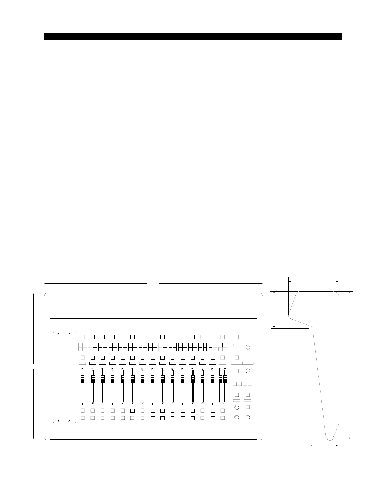
The D-16 digital audio console is designed for countertop mounting.
Consoleplacementshouldavoidproximitytoanyelectromagneticfields,
such as large power transformers, motors, and fluorescent lighting
fixtures.
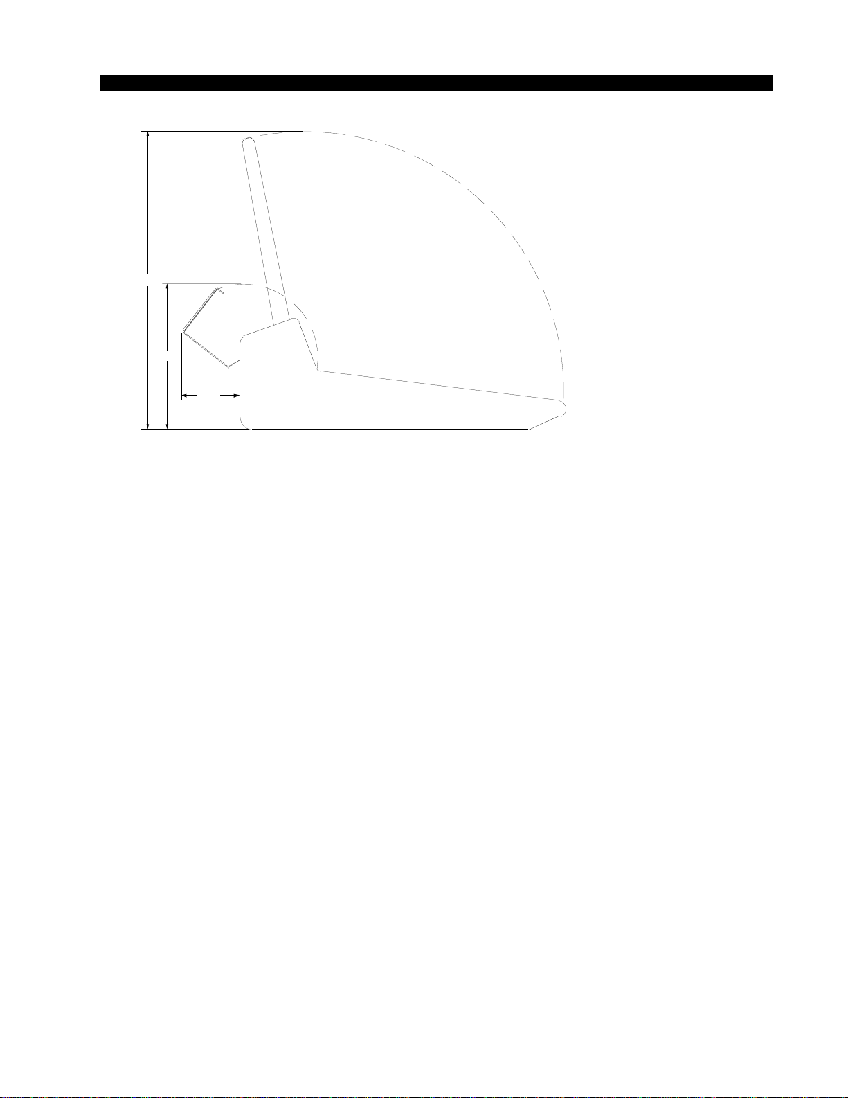
The console extends approximately 6” above the countertop at the
meterbridge.
Do not connect the D-16 console to its power supply (and do not
connectthepowersupplytotheACpowerline)untilinstructedtodo
so.
NOTE: This console
contains static-sensi-
tive devices. Normal
precautions against
staticdischargeshould
be observed.
29.500
19.837
6.755
19.837
3.900
5.000
INSTALLATION and POWER
page 1 – 3
D-16 / Feb 2003
NOTE: The console’s
face panel does not
needtobeopeneddur-
ing operation. It is only
for service access.
System Ground
The first step is to ground the console.
Note that as supplied from the factory, console rackmount power
supply common, audio ground, and the D-16 mainframe are connected
togetherattheconsole,butareNOTconnectedtoelectricalgroundandthe
chassis of the power supply. Safety requirements dictate that a positive
connectionfromtheconsolemainframetoelectricalgroundbemadeinthe
completedinstallation.Usethegroundinglugontherearofthemainframe
to establish your system ground. The grounding lug may be found at the
rear of the console, on the rear frame panel, to the left if you are looking
at the rear of the console.
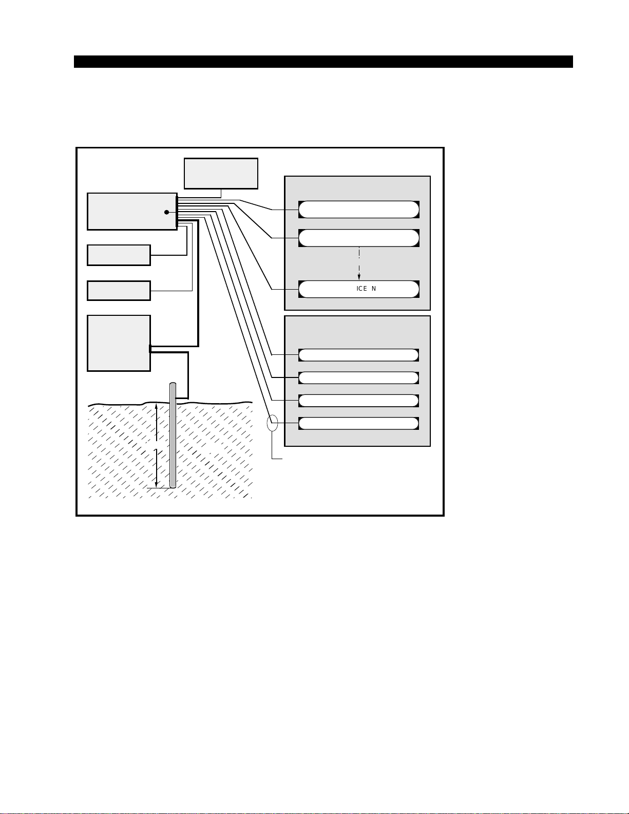
The system ground serves two important purposes:
(1) It provides a zero signal reference point for the entire audio system;
(2) It assures safety from electrical shock.
There exist two terms that one encounters in a discussion of ground:
(A)EARTHGROUND,whichisusuallyaheavycopperroddrivenintothesoil
adjacent to the building (around 6 feet down) or a connection to the copper water
pipes leading into the building. Either is acceptable (unless, of course, the water
pipe is made of plastic).
(B) THE POWER COMPANY EARTH CONDUCTOR that enters the build-
ing at the power line breaker box; this conductor should be (and is often by code)
tiedto theabove-mentioned earth ground at one point. This point is the SYSTEM
EARTH GROUND.
TIE THE CONSOLE GROUND LUG TO THE SYSTEM EARTH
GROUND. TIE EVERY PIECE OF EQUIPMENT IN THE ENTIRE
AUDIO SYSTEM TO THE CONSOLE GROUND LUG. If the system
18.150
3.500
8.900
INSTALLATION and POWER
page 1 – 4
D-16 / Feb 2003
CONSOLE
2-TRACK
MULTI-TRACK
AC BREAKER
BOX
DEVICE 1
DEVICE 2
DEVICE N
CONSOLE POWER SUPPLY
CONTROL ROOM POWER AMP
STUDIO POWER AMP
OTHER
POWER COMPANY
EARTH GROUND
HEAVY
(#4 or #6)
COPPER
WIRE
HIGH POWER
EQUIPMENT RACK
COPPER ROD
SOIL
3-wire ground or separate wire run from chassis
EFFECTS RACK
MIC PANEL
GND
TYPICAL SYSTEM
GROUNDING SCHEME
etc.
3–5 ft.
Tie the console ground lug
terminal strip to the system
earthground. Tieeverypiece
of equipment in the entire
audio system to the console
ground lug terminal strip.
earth ground point is inaccessible, tie the console ground lug to the
power company earth conductor at the main breaker box (see drawing
"Typical Grounding Scheme" below).
Each piece of equipment should be connected by its own ground
wire(usuallytheroundthirdpinontheACcord).Thismeansthatevery
AC outlet must have a separate conductor run to the console ground
lug; the outlets cannot be daisy-chained as is normally encountered in
commercial and residential AC systems. Any equipment not supplied
with3-wireACcablesmusthaveindividualgroundwires(16gaugeor
larger) connected to their chassis grounds and then run to the console
ground lug terminal strip.
Further Grounding Details
Checkallequipmenttobeabsolutelycertainthateachunitispower
transformer isolated from the AC mains to prevent safety hazards.
Itisassumedthatineachpieceofaudioequipmenttheaudioground
andthechassisaretiedtogetheratsomepoint.Anypieceofequipment
lacking a grounded chassis is likely to be prone to interference
problems.

I N S T A L L A T I O N a nd P OWER
page 1 – 5
D-16 / Feb 2003
Locate all unbalanced audio equipment in the same rack if possible, to
minimize chassis ground potential differences. It may also be helpful to
insulate each piece of unbalanced equipment from its mounting rails in the
rack by means of nylon 10-32 screws and insulating washers between rails
and faceplates.
Once the system is properly grounded, proceed with the console
power supply installation and connection (next section).
Power Supplies
The D-16 console is powered by an Audioarts Model PSR-100 rackmount
power supply. This unit occupies two 19” wide rack spaces (total height
3-1/2”). Convection cooled, it requires ample ventilation space above and
below it.
Note that the power supply should be mounted in an equipment rack
within fifteen feet of the console (but no closer than 3 feet). Avoid locating
any high gain equipment (such as phono preamps, tape recorders, etc.) too
near the rackmount supplies, to avoid magnetic interference into that
equipment.
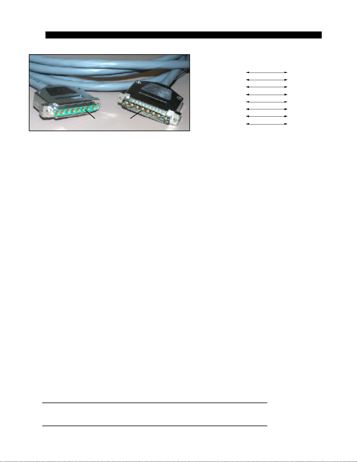
Once the supply is rackmounted, it should be connected to the console
using the factory supplied cable. The cable has two different types of
connectors on it: an 8-pin female connector that connects to the console’s
power supply connector, and an 8-pin male connector that plugs into the rear
of the rackmount PSR-100 power supply. The console’s power supply
connector is located at the rear of the console, at the right end of the
meterbridge bottom pan. If you are using one supply, connect it to the
console connector. If you are using two supplies (failsafe option), connect
D-16 / June 2006
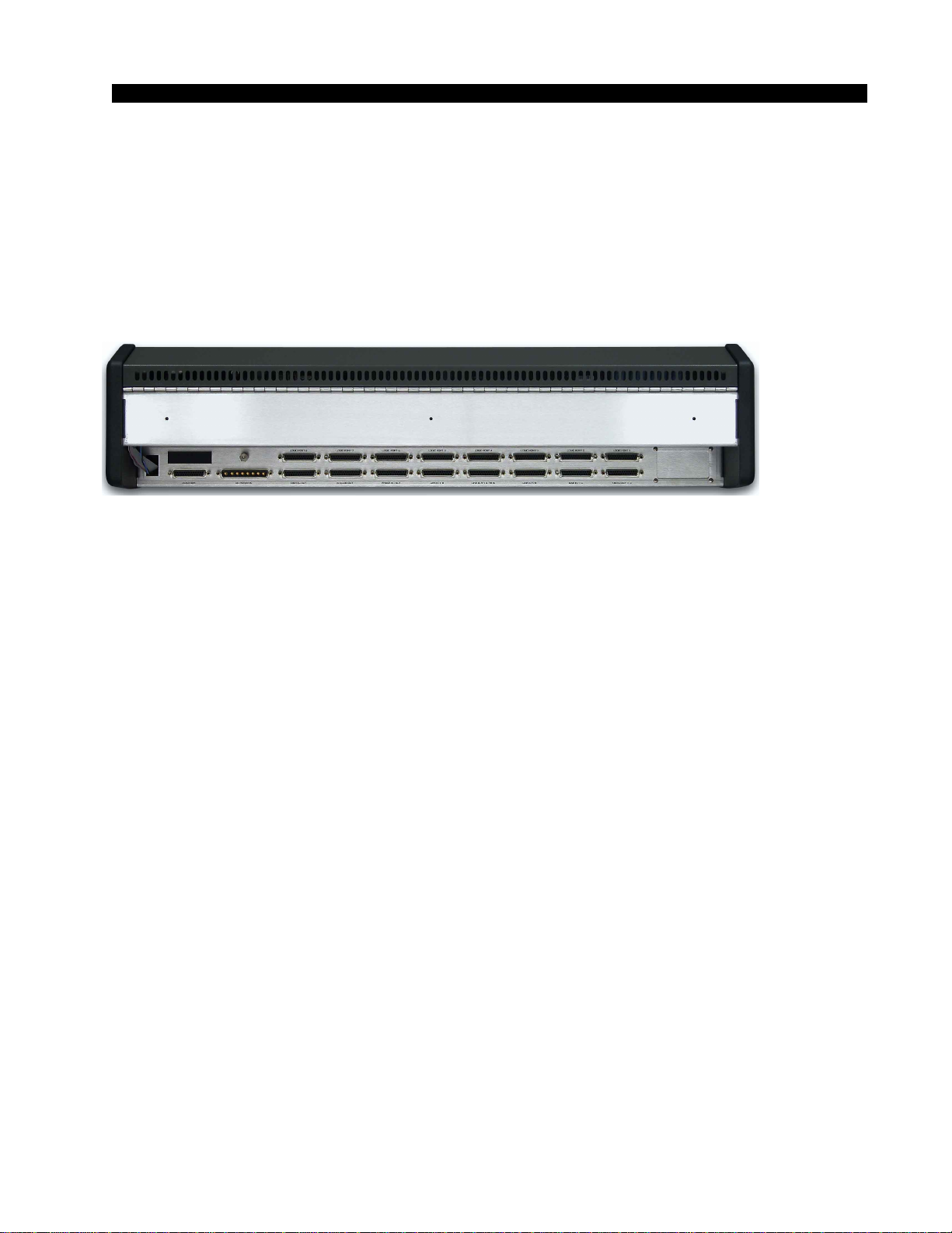
Front view of the PSR-100
rackmount power supply
Rear view of the PSR-100
rackmount power supply
If failsafe redundant sup-
plies have been ordered,
you will be installing two
units and an additional
rackmount panel.
I N S T A L L A T I O N a nd P OWER
page 1 – 6
D-16 / Feb 2003
the long power supply cable to the center connector of the rackmount failsafe
panel. Then connect one supply with a short cable to either of the two
remaining connectors on the failsafe panel and connect the second supply
with a short cable to the last connector.
Note that each power supply is fitted with a 3-wire grounded AC cord
that should be plugged into a "clean" AC power source, that is, an AC source
that feeds only the control room audio gear. This source should be a separate
feed from those powering lighting, air-conditioning, or any other non-audio
machinery. The third pin ground wire of the AC source should be tied to the
central system ground point.
Failsafe Dual Redundant Supply
Wheatstone failsafe power supply systems use two separate rackmount
power supplies for each piece of powered equipment. Though either is
capable of running a full load on its own, in failsafe operation both units run
in tandem: if one fails, the other takes over, assuring uninterrupted opera-
tion.
In order for failsafe systems to perform as designed, always have BOTH
rackmount supplies powered up and connected to their associated equip-
ment.
Energizing
Assuming the D-16 console mainframe is properly placed and grounded,
and its PSR-100 power supply correctly rackmounted and connected to the
console, you may now energize the power supply by plugging it into the AC
mains. The green “+PH” (phantom) LED and all of the “GOOD” LEDs on
the power supply front panel should light up to indicate the presence of their
respective voltages. The console's VU meters will illuminate and individual
module switches will assume factory default settings.
Note: To de-energize the console, unplug the rackmount power supply’s
AC cord from the AC mains. Never de-energize the console by disconnect-
ing the cable that connects the console and power supply together.
Onceyouhaveverified properpower-up,unplugtherackmountpowersupply
to de-energize the console. You may now proceed to wire up audio and
control connections.
D-16 / June 2006
The power feed recom-
mended in the text is of-
ten installed and referred
to in studios as an “iso-
lated AC ground” outlet.
It is usually orange in
color.
1
2
3
4
Phantom
Digital Common
Digital Common
+ Digital
PIN PIN
8-pin Connector
Male
Power Supply End
8-pin Connector
Female
Console End
5
6
7
8
+ Digital
Audio Common
- V
+ V
VIO
GRN
BRN
WHT
ORG
BLK
BLU
RED
PS Cable Pinout
1
2
3
4
5
6
7
8
VIO
GRN
BRN
WHT
ORG
BLK
BLU
RED
Console
End Power Supply
End
INSTALLATION and POWER
page 1 – 7
D-16 / Feb 2003
Audio and Control Wiring
All audio and control I/O connections to the D-16 console are made
through multipin DB-25 connectors located on the rear panel of the
console.
The factory supplied hand crimping tool is used for all I/O wiring
connections to and from the console (see instruction on the page 1-9).
ConnectionProcedures
Assuppliedfromthefactory,theconsolerequiresnologicconnections
tofunction.Thereforeanorderlyinstallationbeginswiththeaudiowiring.
Proceed through the manual, chapter by chapter, until all slots have been
wiredto suit your particular installation requirements. Once properaudio
operationisverified,gobacktoChapter3andproceedwithcontrolwiring.
Digital Audio Connections
CABLE-AllAES/EBUinputandoutputdigitalaudioconnectionsare
balanced and should be made using a high quality digital audio cable. Be
sure to select a digital audio cable with an integral drain wire of the same
wire gauge (AWG) as the twisted pair. Typical AES/EBU digital audio
cablehasaverylowcharacteristiccapacitanceperft(pF/ft),andanominal
impedance of 110Ω. High quality digital audio cable offers better signal
transmission performance versus typical analog audio cable, especially
overlongcableruns.Checkthecablemanufacturer’sdatasheettobesure
the cable you plan to use will work in your application.
CONNECTORS - All AES/EBU connections are made with the
suppliedDB-25connectors.Thesecrimpstyleconnectorswillacceptwire
gauge 22 - 28AWG.
SPDIF INPUTS - The SPDIF (Sony/Phillips Digital Interface) or
“consumer” digital audio interface is a two wire unbalanced signal,
typically on a single RCA style connector. To connect SPDIF devices to
the D-16 console simply wire the SPDIF center conductor (HOT) to the
digital input HI pin and SPDIF shell (ground) to the LO pin. Connect the
digital input SH at the console end only.

INSTALLATION and POWER
page 1 – 8
D-16 / Feb 2003
Unbalanced Connections (analog audio)
ANALOG INPUTS — Wire to the console with typical shielded two
conductor cable (like Belden 9451), just as if you were connecting a
balancedsource. At the unbalancedsource machine’s output, connectthe
black wire (LO) to the shield.
ANALOGOUTPUTS — D-16 consoles use abalanced output circuit
which behaves exactly like the secondary of a high-quality transformer,
withnocentertap—thisoutputisbothbalancedandfloating.EithertheHI
orLOsideoftheoutputshouldbestrappedtoground,withtheoutputtaken
from the other side. (Normally you’d strap LO to ground, and take HIGH
to feed your unbalanced equipment.)
Installation Tip
In an effort to pack the D-16 rear panel with the maximum signal
capability, we have employed multipin DB-25 connectors. It is certainly
possibletowireupdirectlyfromtheDB-25matingplugstotheperipheral
circuitry, such as microphones, CD players, control room and studio
speakers, and STL. However, if you anticipate making frequent wiring
changesafterinstallationyoushouldconsiderusingpunchblocks,orsome
otherinterconnectsystemthatwillallowyoutochangeasinglesignalline
without interfering with seven other signals. And contact the factory or
your dealer to find out about available prewire options.
D-16 / Jul 2003
INSTALLATION and POWER
page 1 – 9
D-16 / Feb 2003
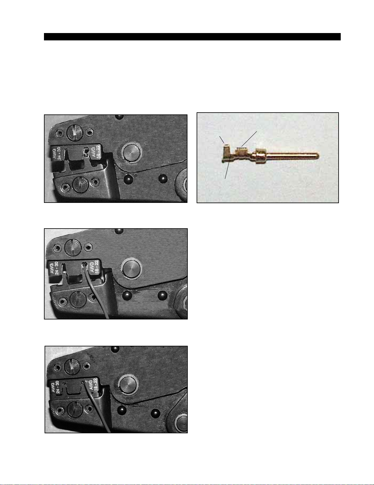
HAND CRIMP TOOL WIRING INSTRUCTIONS
The supplied hand crimping tool (W/S#850067) is used for all I/O wiring con-
nections to and from the console. It is to be used with the supplied pin (figure 1)
intended for 22"-28" gauge wire.
1) Strip wire approximately 3/16" (insert in
proper wire stripper, rotate one half turn, and
pull insulation off wire).
2) Leaving wire aside for the moment, with
crimping tool fully open (engraved side toward
you) bring a terminal into position from the
unmarked side of the tool. Place the conductor
tabs (inner set as shown in figure 1) on the
"18-22" or "24-30" (depending on the wire) an-
vil (slightly curved surface) so that the circular
portion of the tabs rests in the curved surface
of the anvil and the two tabs face up into the
walls of the female jaw. The insulation tabs will
be flush with the top of the tool (figure 2).
3) Close tool very slightly, only to the point
of holding the terminal in position (figure 2).
4) Insert wire into terminal until wire insu-
lation is stopped by conductor tabs (figure 3).
CRIMP by squeezing handles until jaws are fully
closed (figure 4).
5) If there is an insertion error or if a circuit
change is needed, you'll need to use an extrac-
tor tool to remove terminals (see next page).
Note that metallized plastic hoods for each
connector are also supplied with the console.
(1) Pin crimp terminal
CONDUCTOR
TABS
INSULATION
TABS
INSULATION
STOPS HERE
(2) The terminal conductor tabs (pointing UP) are
placed in anvil 18-22; the terminal's insulation tabs
extend in front towards the camera.
(3) The stripped wire is placed into the terminal and
crimped. Note the wire's insulation must stop just
short of the conductor tabs (detail)
(4) Final step: jaws fully closed; the insulation tabs
have been crimped.
Insulation
stops here
D-16 / Jun 2004

INSTALLATION and POWER
page 1 – 10
D-16 / Feb 2003
(5) Place extractor tip over pin terminal to be
removed.
If you accidentally insert a crimp terminal
pin into the wrong socket, you'll need to use
the supplied pin extractor tool (W/S#850069)
to remove terminal pin, and correct your mis-
take without having to sacrifice a connector.
Place extractor tip (red side) over terminal pin
to be removed (figure 5), and press it down-
wards motion until tip rests upon Housing.
Then pull out the terminal pin from Housing.
It should never be necessary to discard a con-
nector due to a wiring error.
EXTRACTOR PIN INSTRUCTIONS
D-16 / Jun 2004

page 2 – 1
D-16 / Feb 2003
CONSOLE FEATURES
Console Features
Chapter Contents
Overview ..................................................................................... 2-2
Inputs .......................................................................................... 2-3
Analog Mono Mic Level Inputs ............................................................................... 2-3
Analog Stereo Line Level Inputs ............................................................................ 2-3
Digital Stereo Line Level Inputs.............................................................................. 2-3
Producer Talkback Input......................................................................................... 2-3
Sources ....................................................................................... 2-3
Faders ......................................................................................... 2-4
Outputs ....................................................................................... 2-4
Mutes and Tallies ....................................................................... 2-4
Other Features............................................................................ 2-5
Console Layout Drawing ........................................................... 2-6
page 2 – 2
D-16 / Feb 2003
CONSOLE FEATURES
Console Features
Overview
The D-16 console consists of fourteen faders with associated switches, a dual
fader PHONE section, also with associated switches, a MONITOR SECTION, a
CONTROL SECTION, and a TIMER SECTION. Each section is described
below.
Thebasicpurpose ofthe consoleis totakesomeofthe manyaudio signalsthat
are wired to the console inputs, and generate several outputs that combine these
inputsinvariousgroupsandatvariousdegreesofloudness,orsignalstrength.The
typicalapplicationisinaradiostationwhereitisdesiredtodevelopthesignalsthat
the station will broadcast (the on air signal), as well as several additional signals
for recording and monitoring.
Table of contents
Other AudioArts Engineering Recording Equipment manuals

AudioArts Engineering
AudioArts Engineering R-55 User manual

AudioArts Engineering
AudioArts Engineering R-60 User manual

AudioArts Engineering
AudioArts Engineering D-75 User manual

AudioArts Engineering
AudioArts Engineering D-76 User manual

AudioArts Engineering
AudioArts Engineering D-70 User manual

AudioArts Engineering
AudioArts Engineering R-5 User manual


