Mediant 2000/SIP User’s Manual Contents
Mediant 2000/SIP 8 Document #: LTRT-00688
List of Figures
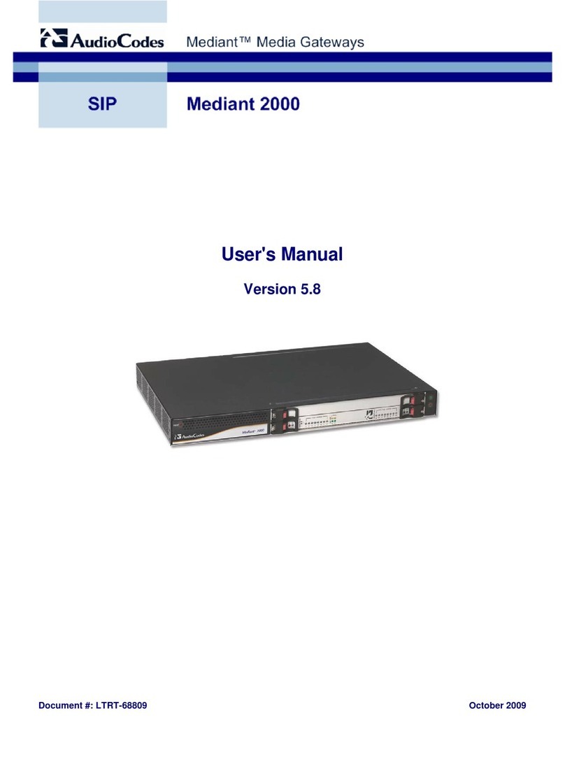
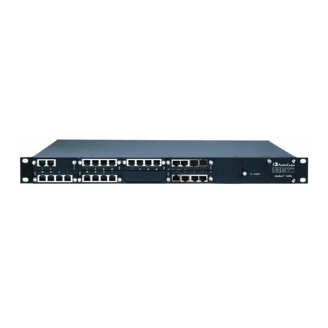
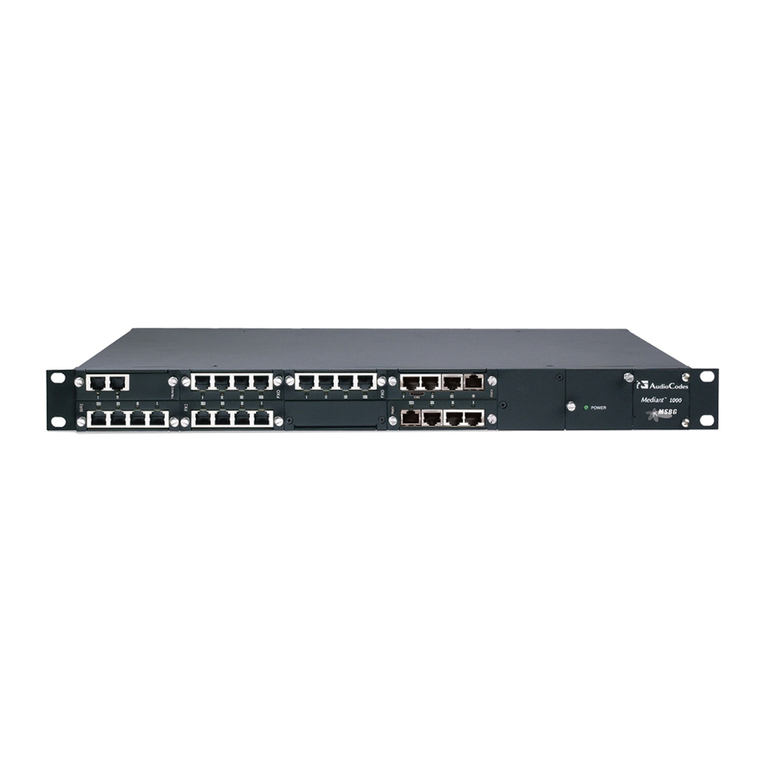
Figure 1-1: Mediant 2000/SIP Front View ........................................................................................................11
Figure 1-2: Mediant 2000/SIP Rear View.........................................................................................................12
Figure 1-3: Typical Mediant 2000/SIP Gateway Application............................................................................12
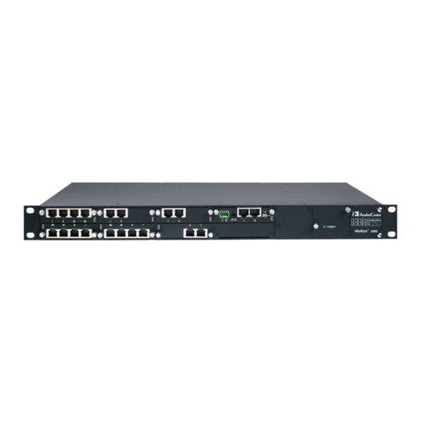
Figure 2-1: Mediant 2000/SIP Gateway Front View.........................................................................................15
Figure 2-2: Front and Upper View of TP-1610 cPCI Board..............................................................................16
Figure 2-3: View of Rear TP-1610 cPCI Board ................................................................................................16
Figure 2-4: 50-pin Female Telco Board-mounted Connector...........................................................................18
Figure 2-5: Pinouts of RJ-45 LAN and RJ-48c Trunk Connectors ...................................................................18
Figure 2-6: Mediant 2000/SIP Front Panel Supporting up to 16 Trunks..........................................................20
Figure 2-7: Mediant 2000/SIP Front Panel Supporting up to 8 Trunks............................................................21
Figure 2-8: Mediant 2000/SIP Rear Panel with two 50-pin Connectors for 16 Trunks ....................................22
Figure 2-9: Mediant 2000/SIP Rear Panel with 8 RJ-48c Connectors for 8 Trunks.........................................23
Figure 2-10: Mediant 2000/SIP Rear Panel with 4 RJ-48c Connectors for 4 Trunks.......................................24
Figure 2-11: Mediant 2000/SIP Rear Panel with 2 RJ-48c Connectors for 2 Trunks.......................................25
Figure 2-12: Mediant 2000/SIP Rear Panel with 1 RJ-48c Connector for 1 Trunk ..........................................26
Figure 3-1: Enter Network Password Screen...................................................................................................30
Figure 3-2: SIP Quick Setup Screen ................................................................................................................31
Figure 3-3: AudioCodes Configuration Utility Main Screen..............................................................................36
Figure 3-4: Preferences Screen .......................................................................................................................36
Figure 3-5: Client Configuration........................................................................................................................37
Figure 3-6: AudioCodes Configuration Utility - Client Found............................................................................38
Figure 4-1: SIP Call Flow Example...................................................................................................................44
Figure 5-1: ini File Structure .............................................................................................................................64
Figure 5-2: SIP ini File Example.......................................................................................................................65
Figure 5-3: General Data Sheet .......................................................................................................................66
Figure 5-4: SIP Parameters Sheet ...................................................................................................................67
Figure 5-5: End Points Data Sheet...................................................................................................................67
Figure 5-6: Routing Table Data Sheet..............................................................................................................68
Figure 5-7: E1/T1 Parameter Sheet .................................................................................................................68
Figure 5-8: Download Selection Screen...........................................................................................................73
Figure 5-9: File Selection Screen.....................................................................................................................74
Figure 6-1: Enter Network Password Screen...................................................................................................80
Figure 6-2: Web Server – SIP Quick Setup......................................................................................................80
Figure 6-3: Protocol Management Menu..........................................................................................................81
Figure 6-4: General, Proxy Server and Authentication Parameters.................................................................82
Figure 6-5: VoIP Coders...................................................................................................................................82
Figure 6-6: Early Media Parameters.................................................................................................................82
Figure 6-7: of Manipulation and Routing Modes ..............................................................................................83
Figure 6-8: Supplementary Services................................................................................................................83
Figure 6-9: ISDN and CAS Parameters............................................................................................................83
Figure 6-10: Miscellaneous Parameters...........................................................................................................83
Figure 6-11: Trunk Group Table.......................................................................................................................84
Figure 6-12: Phone Number Manipulation Table for IP !Tel calls.................................................................85
Figure 6-13: Tel to IP Routing Table ................................................................................................................85
Figure 6-14: IP to Trunk Routing Table............................................................................................................86
Figure 6-15: Advanced Configuration...............................................................................................................87
Figure 6-16: Network Settings Screen..............................................................................................................88
Figure 6-17: Channel Settings..........................................................................................................................89
Figure 6-18: E1/T1 Trunk Settings ...................................................................................................................90
Figure 6-19: TDM Bus Settings Screen............................................................................................................91
Figure 6-20: Configuration File Screen.............................................................................................................92
Figure 6-21: Regional Settings Screen.............................................................................................................93
Figure 6-22: Change Password Screen ...........................................................................................................94
Figure 6-23: Status and Diagnostics Menu ......................................................................................................94
Figure 6-24: Trunk& Channel Status................................................................................................................95
Figure 6-25: Trunk and Channel Status Color Indicator Key ...........................................................................95
Figure 6-26: Channel Status.............................................................................................................................96
Figure 6-27: Message Log Screen...................................................................................................................96
Figure 6-28: Versions Screen...........................................................................................................................97
Figure 6-29: Software Update Menu ................................................................................................................97


