Audiolab M-DAC User manual

M-DAC

M-DAC
VERSION HISTORY
Rev
V01
Date Update Content
July 10, 2012 First Version

CONTENT
M-DAC
Introduction
ia
screen of Bottom
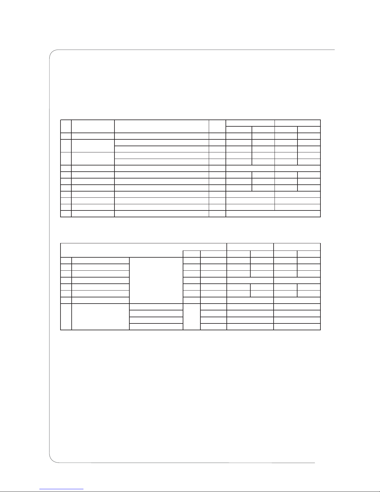
Assembly Parts List
Electronic Parts List
Product Version Deviation
/
Specification
Assembly Sketch
Schematic Diagram
Wir ng Di gram
Silk Top
Maintenance Alignment Procedure
1.
2.
3.
4.
5.
6.
7.
8.
9.
1
2-3
4-5
6-8
9
10-15
16-17
18-19
20-23
24-25
10.

INTRODUCTION
M-DAC
No part of this document may be reproduced or transmitted in any form or by any means,electronic or
mechanical, for any purpose, without the express written permission of International Audio Group
Limited (IAG)
This manual is for the exclusive use of IAG, its approved distributors and approved UK service agents.
No part of this manual shall be transferred to any other party without the express written permission of
IAG.
It is the responsibility of the user to ensure that all the information contained in this manual is current.
Notification for new issues of this manual and minor updates will be given via the IAG web-site or on
request.
This manual has been prepared with the greatest care, it is intended for information only and no liability
shall be accepted for errors or changes to specification.
For further service information, parts lists and updates, please contact our web-site at
www.international audio group.com .
2012 International Audio Group Limited. All rights reserved.
C
1
SPECIFICATION
M-DAC
M-DAC-Specification and Features-P1/2
2
.
.
.
.
.
.
.
32Bit 84.000MHz 512 Element MultiBit Array DAC
Asynchronous USB supporting 24 Bits / 96kHz with Remote Control of PC / MAC
MediaPlayer via HID support
x2 192KHz 24Bits Coax SPDIF Digital Inputs
x2 96KHz Optical Digital Inputs
High Current, High Linearity RCA Single Ended & XLR True Balanced with fully discrete
JFET CROSS* Class A Output stage's
High Current, High Linearity CROSS* JFET Class A Headphone Amplifier
Triple cascaded Jitter attenuation stages, with triple cascaded Asynchronies Clock
domain isolation all but eliminating the First order effects of Jitter from the external input
Test condition: AC~253V, COAX: 997Hz Digital Signal,SR: 48kHz
Load: 10 kohms impedance, with Filter NAL setting
Z-out: 20ohms
M-DAC Performance Test
LR LR
1 Output Level 997Hz,Digital COAX Input Vrms 2.21 2.22 4.23 4.22
stereo 997Hz output 2V % 0.001 0.001 0.001 0.001
stereo 20kHz output 2V % 0.0005 0.0005 0.0002 0.0002
Line output, dB 108 108 116 116
Line output, with 22-22kHz BW and A-wtd dB 112 112 120 120
4 Gain 0dBFS Input (0dBV) dB
5 Noise Level no signal,pre-amp out dBV -100.8 -101.4 102.5 102.7
6 DC Offset To measure the output DC Voltage mV 0.8 0.5
7 Crosstalk L/R Cross talk,refer to 997Hz dB 108 108 116 116
8 L/R different L/R different,un-balance dB
9 Phase no reverse deg
10 Freq Respond Refer to 997Hz input as 0dBr,+/-0.5dB Hz
12 Idle Current Idle Current,230VAC mA
Condition Units XLR
13.2
0.01
7.1
20-20k
0
18mA
0
20-20k
0.05
2THD
RCA
S/N3
No. Test Items
Digital OUT Test
Units Limit L R LR
1Output Level dBFS 0±0.05 0 0 00
2Harmonic Distortion % <0.005 0.00001 0.00001 0.00001 0.00001
3L/R phase deg ±1 0 0 00
4 Digital Output Intensity Vpp >500
5 Level Linearity dBFS -143 -143 -143 -143
6 Frequency response dB 0.5dB 0.01 0.01 0.01 0.01
7 Output impedance ohm 75±1
32KHz
44.1KHz 44.1±0.01
48KHz 48±0.01
96KHz 96±0.01
No. Test item Track
44.1KHz
48KHz
96KHz
48KHz
8 Sampling Rate kHz
96KHz
44.1KHz
COAX
32, 44.1,48,96KHz
(16,24bit) 580
OPT
/
75

sources on the Digital to Audio Conversion process
Selectable DAC Mode or Digital Pre-Amplifier Mode, allowing direct connection to Power
Amplifiers and Active speakers in Digital only systems
2.7” High contrast OLED display
“Bit Perfect” Digital Data source analyzer
Intelligent real-time Bit Depth analysis engine Displays the “True” Bit depth of the Digital
input source
Digital Data Decorrelation Engine Decorrelates the fixed “LSB's” data pattern within the
Audio data stream when less then 24Bits. Data decorrelation at the DAC substrate level
reduces both Digital and Analogue Second order effects within the DAC at the silicon Die
level
MS Windows LSB Data restoration for “Bit Perfect” reply corrects Windows' LSB rounding
errors. Allows Bit Perfect “Plug and Play” with Windows Media Player
ASYNC USB Buffer level display to insure correct functionality and diagnostics of the USB
HOST device in ASYNC Audio streaming mode
“Actual” or “Nominal” Sampling Frequency display displays the TRUE input sampling
frequency with 1Hz resolution
Digital level meters in dB with Peak hold
CD / DVD SPDIF subcode embedded Track and Time Display
Advanced De-Jittered Optical and Coax SPDIF Output, with USB to SPDIF output.
Selectable Optical or Coax Clock-Lock interface allowing “Jitter Free” Clock-Locked
connection with compatible CD transports etc.
Full Remote Control + External Remote / BUS I/O loop
26 Internal regulated supply rails
10 Ultra Low Noise, Low Impedance Discrete Regulators
7 User Selectable Digital Filters Fully Software upgradeable via the USB Port
Master Clock Jitter less then 3pS Short Term - Measured directly at DAC “XOut”
Organic Ultra Low ESR capacitors, High Tolerance Polypropylene film / Foil capacitors,
Ultra Stable Very Low VCR 0.1% MELF SMD resistors, 4 Layer PCB
External upgradeable Power supply interface for a future upgrade path
CROSS Current Regulated Output Stage Solution
.
.
.
.
.
.
.
.
.
.
.
.
.
.
.
.
.
.
.
*
SPECIFICATION
M-DAC
M-DAC-Specification and Features-P2/2
3

ASSEMBLY SKETCH
M-DAC
4
M-DAC-Product Exploded Drawing- 1/1P
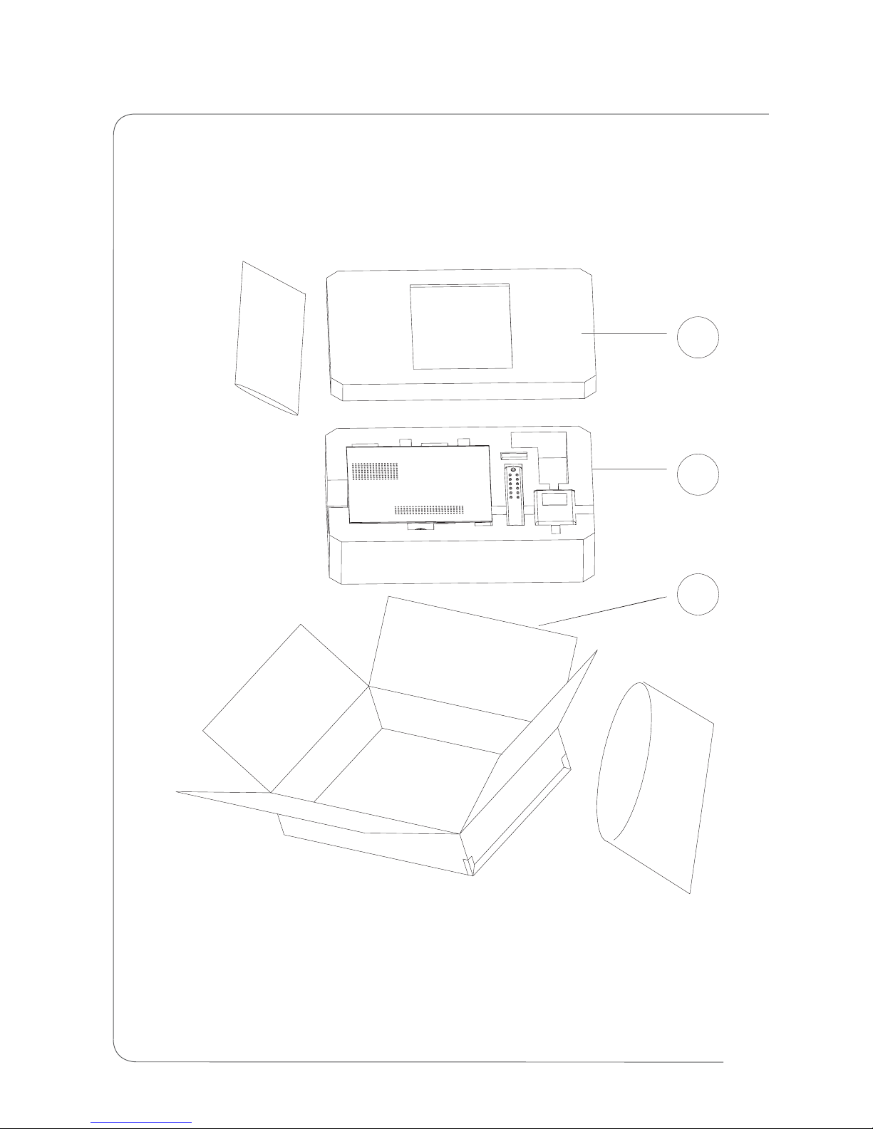
ASSEMBLY SKETCH
M-DAC
5
3
2
1
M-DAC-Packing Exploded Drawing- 1/1P

SCHEMATIC DIAGRAM
M-DAC
M-DAC-Mainboard-P1/1
6

SCHEMATIC DIAGRAM
M-DAC
M-DAC-Frontboard-P2/2
7

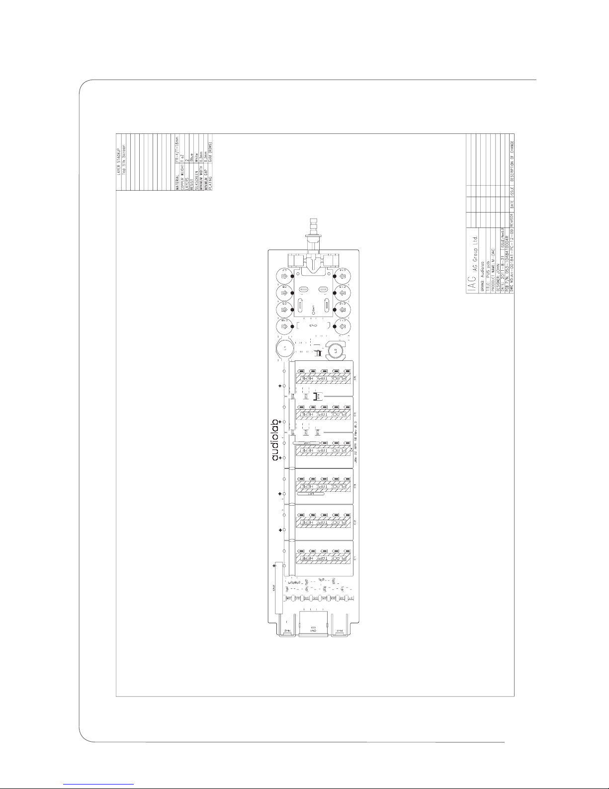
SCHEMATIC DIAGRAM
M-DAC
M-DAC-PSU Board-P1/1
8
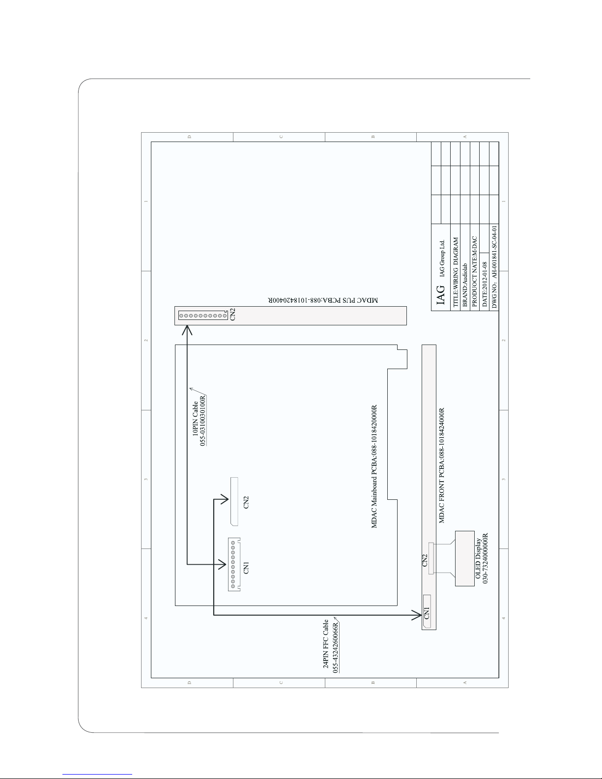
WIRING DIAGRAM
M-DAC
M-DAC-Wiring Diagram-P1/1
9

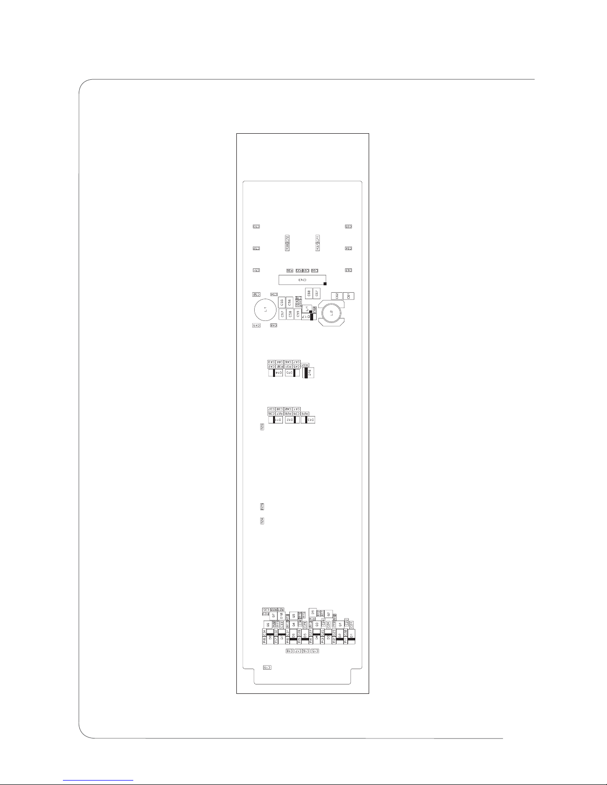
SILK TOPSCREEN OF BOTTOM
/
M-DAC-Mainboard-Top-Silkscreeen-P1/1
M-DAC
10

M-DAC
SILK TOPSCREEN OF BOTTOM
/
M-DAC-Mainboard-SMD-Silkscreeen-P1/1
11

SILK TOPSCREEN OF BOTTOM
/
M-DAC-Front Board-Top-Silkscreeen-P1/1
M-DAC
12

SILK TOPSCREEN OF BOTTOM
/
M-DAC-Front Board-SMD-Silkscreeen-P1/1
M-DAC
13
SILK TOPSCREEN OF BOTTOM
/
M-DAC-PSU Board-Top-Silkscreeen-P1/1
M-DAC
14
SILK TOPSCREEN OF BOTTOM
/
M-DAC-Front Board-SMD-Silkscreeen-P1/1
M-DAC
15

MAINTENANCE ALIGNMENT PROCEDURE
M-DAC
M-DAC-Ageing Test Step-P1/2
16
MDAC Soak Test procedure Rev 0.1
Post Soak test performance verification
1. Insure that Mains input voltage is set to +/- 5% of rated input voltage.
2. Lock to an External SPDIF source Play Music file / source.
3. Insure Display, Knob and Buttons function correctly.
4. Confirm R/C function.
5. Insure audio is replayed correctly (Headphones can be used).
6. Soak test for > 8Hours.
7. Insure Display and Buttons function correctly.
8. Insure audio is replayed correctly (Headphones can be used).
9. Inspect internals of Unit for Blown Electrolytic capacitors Blown SMD Components etc.
1. Set to COAX1, (Set Digital Generator on AP to 44.1KHz, 24 Bit, Dither, 997Hz, 0dB).
2. Check Unit is “Locked” and indicates 44.1kHz Freq. (As indicated on Display).
3. Check L & R SE Audio Outputs, Level 2.1V RMS (+/- 0.1dB).
4. Check L & R SE Audio THD, 0.0025% Max (Norm 0.001%).
5. Set AP to 997Hz -60dB, check L&R SE, SNR >54dB (=>114dB).
6. Set AP to -120dB 997Hz, Check L&R SE outputs, DC Level <= +/-5mV.
7. Set Digital Generator on AP to 44.1KHz, 24 Bit, Dither, 997Hz, 0dB.
8. Check L & R Balanced Audio Outputs, Level 4.2V RMS (+/- 0.1dB).
9. Check L & R Balanced Audio Outputs THD, 0.001% Max (Norm 0.0006%).
10. Set AP to 997Hz -60dB, check L&R Balanced, SNR >58dB (=>118dB).
11. Set AP to 44.1KHz, 24 Bit, Dither, 997Hz, 0dB.
12. Confirm COAX2, Optical 1&2 function (Locked indicated on display & Audio Signal
output).
13. Confirm USB function, replay Stereo 997Hz 0dB on PC media player, confirm SE Level
2.1V RMS (+/- 0.1dB), Audio THD, 0.0025% Max (Norm 0.001%).
14. Confirm R/C function.

15. Test Optical and BNC Digital CD Output function (with AP or external DAC), Digital
Output greater then =>500mV Pk-Pk into 75 Ohms.
16. Completion of Post Soak Test performance verification.
1. Connect to audio System (via RCA's), Lock to external SPDIF or USB Source,
confirm no undue noise function OK.
2. Test all Digital inputs (Coax1, 2, Optical1&2)andUSB(WithPC) repeat listening
test.
3. Confirm Remote function.
4. Completion of Listening tests.
1. Restore unit to Factory defaults.
2. End of Shipping settings.
Listening Test
Shipping Settings
MAINTENANCE ALIGNMENT PROCEDURE
M-DAC
M-DAC-Ageing Test Step-P2/2
17
Other manuals for M-DAC
2
Table of contents
Other Audiolab Media Converter manuals


