AudioScience COBRANET ASI2416 User manual
18 November 2008
www.audioscience.com 1 18 November 2008
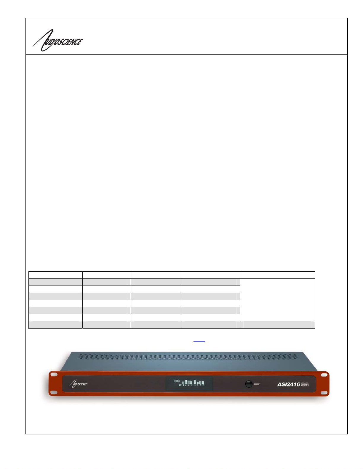
ASI2416
MODULAR COBRANET™ 1RU INTERFACE
1 DESCRIPTION
The ASI2416 is a CobraNet™audio interface in a 1RU
rack mount format providing 16 channels of CobraNet
receive and transmit.
The unit can be populated with up to four function specific
modules, allowing up to 16 channels of analog or
AES/EBU I/O. Each module has an interchangeable
connector that may be configured with either a pluggable
terminal block, StudioHub+® RJ-45, or a 50pin Centronics
connector with XLR breakout cables.
The ASI2416 features a powerful Texas Instruments 32bit
floating point DSP that allows sophisticated
switching/mixing. A graphics display on the unit’s front
panel shows peak meters and CobraNet status.
AudioScience provides application software that may be
used to set up the ASI2416. ASIControl sets up all
internal features of the unit. ASIControl or CobraNet
Discovery allows CobraNet routing connections to be set
up between the ASI2416 and any other CobraNet device
on the network.
2 FEATURES
• 16 CobraNet™input channels and 16 CobraNet output
channels on 100Mbit Ethernet with redundant RJ-45
connectors
• 4 CobraNet Transmitters and 8 CobraNet Receivers.
• 1RU rack-mount unit
• Modular architecture allows up to 4 I/O modules to be
inserted into the back of the unit
• Module connector options include Terminal Block
(Phoenix style), StudioHub+®RJ-45, or 50pin
Centronics connector with XLR breakout cables
• Available modules include eight-channel analog I/O and
eight channel AES/EBU I/O.
• Powerful floating point DSP provides metering, level
control and up to 20 dB gain on all signal paths.
• Interoperable with ASI6416 CobraNet Sound Card and
other third party CobraNet equipment
• Built-in 90-260VAC power supply
3 MODULE INFORMATION
Model Inputs Outputs Input/Output Type Connector Type
ASI1431 8 8 Balanced analog
ASI1432 8 0 Balanced analog
ASI1433 0 8 Balanced analog
ASI1441 8 8 AES/EBU
ASI1442 8 0 AES/EBU
ASI1443 0 8 AES/EBU
ASI1491 (50 pin Centronics)
ASI1492 (StudioHub+ RJ-45)
ASI1493 (Terminal block)
ASI1445 16 16 GPIO Optos/Relays ASI1493 (Terminal block)
Configure the ASI2416 as needed - use the order form found here to customize yours.
CobraNet is a registered trademark of Cirrus Logic and StudioHub+ is a registered trademark of Radio Systems, Inc.

ASI2416
www.audioscience.com 2 18 November 2008
4 SPECIFICATIONS
COBRANET INPUT/OUTPUT
Type CS181022 silicon from Cirrus Logic
Network 10/100BaseT Ethernet with dual redundant RJ-45 connectors
Connector Dual RJ-45
Sample Resolution 16, 20 or 24bit PCM
Sample Rate CobraNet standard 48 kHz
Connections 8 CobraNet receivers and 4 CobraNet transmitters
Latency 1.33, 2.66 or 5.33ms
Control Protocol SNMP using standard CobraNet MIBs.
SIGNAL PROCESSING
DSP Texas Instruments TMS320C6713 @ 225MHz
Control Protocol AudioScience HPI using UDP
ANALOG INPUT/OUTPUT
Type Balanced
Input Level -10 to +24dBu in 1dBu steps
Input Impedance 10K ohms
A/D converter 24bit over sampling
Output Level -10 to +24dBu in 1dBu steps
D/A converter 24bit over sampling
Load Impedance 600ohms or greater
Dynamic Range[1] >105dB (input or output)
THD+N[2] <0.0015% (input or output)
Sample Rates 48 kHz from CobraNet
Frequency Response 20Hz to 20kHz +/-0.25dB, 20Hz to 50kHz +0.25/-3dB
Connectors 3.81mm Terminal Block, 50pin Centronics type with XLR breakout cables or StudioHub+ compatible RJ45.
AES/EBU INPUT/OUTPUT
Type AES/EBU (EIAJ CP-340 Type I / IEC-958 Professional)
Sample Rates Input: 32, 44.1, 48 and 96kHz - uses sample rate converter to convert to CobraNet sample rate.
Output: 32, 44.1, 48 and 96kHz selectable from any input, CobraNet, or dedicated sync input.
Dynamic Range[1] 140dB, any input to any output
THD+N[2] 135dB, any input to any output
Connectors 3.81mm Terminal Block, 50pin Centronics type with XLR breakout cables or StudioHub+ compatible RJ45.
SAMPLE RATE CLOCK
Internal 48kHz from CobraNet
LATENCY (48kHz CobraNet) 5.33ms CobraNet latency 2.67ms CobraNet latency 1.33ms CobraNet latency
Analog input across network to
analog out 8.60ms 5.94ms 4.60ms
CobraNet input to analog Out 6.93ms 4.33ms 2.99ms
Analog input to CobraNet output 6.97ms 4.29ms 2.95ms
Analog input to analog output 1.90ms
REGULATORY
FCC Class A (US)
CE Mark (EN 55022 Class A, EN55024 )
GENERAL
Dimensions 1 RU, 19”(482mm) W x 8”(203mm) L x 1.75”(44mm) H
Weight 7 lb (3.2kg) max, with 16 analog inputs/outputs and terminal block connectors
Operating Temperature 0C to 60C
Power Requirements 100-240VAC, 47-63Hz, 25W max.
NOTES
[1] – Dynamic Range measured using a –60dB 1kHz sine wave and A weighting
[2] - THD+N measured using a +20dBu 1kHz sine wave sampled at 48kHz, 20-20kHz b/w and A weighting filter

ASI2416
www.audioscience.com 3 18 November 2008
5 CONTENTS
1DESCRIPTION..........................................................................................................................................................1
2FEATURES...............................................................................................................................................................1
3MODULE INFORMATION ........................................................................................................................................1
4SPECIFICATIONS ....................................................................................................................................................2
5CONTENTS...............................................................................................................................................................3
5.1 TABLE OF FIGURES...............................................................................................................................................................5
6REVISIONS...............................................................................................................................................................6
7IMPORTANT SAFETY INSTRUCTIONS..................................................................................................................7
8NOTICES...................................................................................................................................................................9
9ARCHITECTS & ENGINEERS SPECIFICATION ..................................................................................................10
10 INTRODUCTION .................................................................................................................................................11
10.1 COBRANET™....................................................................................................................................................................11
10.2 COBRANET ROUTING ........................................................................................................................................................12
10.2.1 Audio Routing Channels ...........................................................................................................................................12
10.2.2 CobraNet Transmitters .............................................................................................................................................13
10.2.3 CobraNet Receivers..................................................................................................................................................14
10.2.4 CobraNet Sample Rate and Latency.........................................................................................................................14
10.2.5 CobraNet References................................................................................................................................................14
11 HARDWARE INSTALLATION............................................................................................................................15
11.1 RACK MOUNTING ..............................................................................................................................................................15
11.2 ETHERNET CONNECTION ...................................................................................................................................................15
11.3 AC POWER ........................................................................................................................................................................15
11.4 MODULES AND AUDIO CONNECTIONS ...............................................................................................................................16
11.4.1 Modules.....................................................................................................................................................................16
11.4.2 Connectors................................................................................................................................................................16
12 OPERATION........................................................................................................................................................17
12.1 POWER UP SEQUENCE ........................................................................................................................................................17
12.1.1 AC Power..................................................................................................................................................................17
12.1.2 Firmware images......................................................................................................................................................17
12.1.3 Firmware loading sequence......................................................................................................................................17
12.1.4 Loading the factory firmware image.........................................................................................................................17
12.2 FRONT PANEL DISPLAY .....................................................................................................................................................17
12.2.1 CobraNet Transmit and Receive Peak Meters Display.............................................................................................18
12.2.2 CobraNet Bundle Number and Channel Settings Display ........................................................................................19
12.2.3 MAC and IP Address Display...................................................................................................................................19
12.2.4 Product Information Display....................................................................................................................................20
12.2.5 Module Input/output Meters – Analog Display.........................................................................................................20
12.2.6 Module Input/Output Meters – AES/EBU Display....................................................................................................21
12.3 RESETTING ALL CONTROLS TO DEFAULT SETTINGS............................................................................................................22
12.4 RESETTING COBRANET PERSISTENCE................................................................................................................................22
12.5 NETWORK INTERFACE........................................................................................................................................................22
12.5.1 ASI2416 Network Mask Assignment.........................................................................................................................22
13 CONFIGURATION ..............................................................................................................................................23
13.1 INSTALLING AND RUNNING ASICONTROL.........................................................................................................................23

ASI2416
www.audioscience.com 4 18 November 2008
13.2 ASICONTROL LAYOUT ......................................................................................................................................................23
13.2.1 Adapter_Info.............................................................................................................................................................24
13.2.2 Level..........................................................................................................................................................................24
13.3 METER...............................................................................................................................................................................25
13.3.1 Interface....................................................................................................................................................................25
13.3.2 Developer..................................................................................................................................................................26
13.4 SETTING AES/EBU CLOCKING .........................................................................................................................................27
13.4.1 AES/EBU Inputs........................................................................................................................................................28
13.4.2 AES/EBU Outputs.....................................................................................................................................................29
13.4.3 Setting the AES/EBU Tx clock source.......................................................................................................................29
13.4.4 Common AES/EBU clocking configurations.............................................................................................................30
13.5 INPUT AND OUTPUT VOLUME ADJUSTMENT........................................................................................................................31
13.6 ROUTING AUDIO USING COBRANET..................................................................................................................................31
13.6.1 Default settings .........................................................................................................................................................31
13.6.2 Persistence................................................................................................................................................................32
13.6.3 Simple crossover example.........................................................................................................................................32
13.7 COBRANET CONFIGURATION.............................................................................................................................................33
13.7.1 CobraNet Configuration Interface............................................................................................................................34
13.7.2 How To Configure and Transmit a Bundle...............................................................................................................36
13.7.3 Change IP Address ...................................................................................................................................................36
13.8 UPDATE FIRMWARE...........................................................................................................................................................37
13.9 SAVE/RESTORE CONFIGURATION ......................................................................................................................................38
13.9.1 Interface....................................................................................................................................................................39
13.10 REFERENCES..................................................................................................................................................................39

ASI2416
www.audioscience.com 5 18 November 2008
5.1 Table of figures
Figure 1. ASI2416 block diagram.............................................................................................................................11
Figure 2. Illustration of a CobraNet bundle going between 2 CobraNet devices.....................................................12
Figure 3. Audio routing channel details....................................................................................................................13
Figure 4. ASI2416 display of CobraNet peak meters and bar height mapping to dBFS range..............................18
Figure 5. ASI2416 bundle display for CobraNet receivers 1 and 2..........................................................................19
Figure 6. ASI2416 MAC and IP address display......................................................................................................19
Figure 7. ASI2416 product information display........................................................................................................20
Figure 8. ASI2416 analog module display...............................................................................................................20
Figure 9. ASI24216 AES/EBU module display. .......................................................................................................21
Figure 10. ASIControl layout......................................................................................................................................23
Figure 11. Adapter information seen in right side of ASIControl.................................................................................24
Figure 12. Using ASIControl to select Line_Out 1.......................................................................................................24
Figure 13. Level displayed by ASIControl for Line_Out 1 ...........................................................................................25
Figure 14. 1A stereo peak meter display. The RMS is the green bar and the peak is the yellow bar...........................25
Figure 15. ASI2416 AES/EBU clocking for Module 1....................................................................................................27
Figure 16. ASI2416 AES/EBU clocking for Module 2....................................................................................................28
Figure 17. Selecting Line_Out 1 in ASIControl prior to setting Tx clock source. ...........................................................29
Figure 18. ASIControl display of AES/EBU Line_Out 1 node controls..........................................................................29
Figure 19. ASIControl selection of AES/EBU output clock source................................................................................30
Figure 20. ASIControl node displays with volumes.......................................................................................................31
Figure 21. Laptop to ASI2416 connection.....................................................................................................................32
Figure 21. Network Driver support selected when installing an AudioScience driver....................................................33
Figure 22. Selecting a CobraNet device to configure....................................................................................................33
Figure 23. CobraNet Configuration dialog box accessed via ASIControl.......................................................................33
Figure 24. Dialog box that opens when “Change IP Address...” is selected.................................................................37
Figure 25. The ASI2416's Firmware Update dialog box.................................................................................................37
Figure 26. Right-clicking on a CobraNet device............................................................................................................38
Figure 27. The Save Configuration dialog box..............................................................................................................39
ASI2416
www.audioscience.com 6 18 November 2008
6 REVISIONS
Date Changes
21 October 2007 Updated format.
07 November 2008 Fix audio channel maps.
18 November 2008 Updated number of modules supported.

ASI2416
www.audioscience.com 7 18 November 2008
7 IMPORTANT SAFETY INSTRUCTIONS
1. Read these instructions.
2. Keep these instructions.
3. Head all warnings.
4. Follow all instructions.
5. Do not use this apparatus near water.
6. Clean only with a dry cloth.
7. Do not block any ventilation openings. Install in accordance with the manufacturer’s instructions.
8. Do not install near any heat sources such as radiators, heat registers, stoves, or other apparatus (including
amplifiers) that produce heat.
9. Do not defeat the safety purpose of the polarized or grounding-type plug. A polarized plug has two blades
with one wider than the other. A grounding type plug has two blades and a third grounding prong. The wide
blade or the third prong is provided for your safety. If the provided plug does not fit into your outlet, consult an
electrician for replacement of the obsolete outlet.
10. Protect the power cord from being walked on or pinched, particularly at plug ends, convenience receptacles,
and the point where they exit from the apparatus.
11. Only use attachments/accessories specified by the manufacturer.
12. Use only with the cart, stand, tripod, bracket, or table specified by the manufacturer, or sold with the
apparatus. When a cart is used, use caution when moving the cart/apparatus combination to avoid injury
from tip-over.
13. Unplug this apparatus during lightning storms or when unused for long periods of time.
14. Refer all servicing to qualified service personal. Servicing is required when the apparatus has been damaged
in any way, such as power-supply cord or plug is damaged, liquid has been spilled or objects have fallen into
the apparatus, the apparatus has been exposed to rain or moisture, does not operate normally, or has been
dropped.
This symbol is intended to alert the user to the presence of uninsulated dangerous voltage within
the product’s enclosure that may be of sufficient magnitude to constitute a risk of electric shock to
humans
This symbol is intended to alert the users to the presence of important operating and maintenance
(servicing) instructions in the literature accompanying the product
ASI2416
www.audioscience.com 8 18 November 2008
CAUTION: To reduce the risk of electric shock, do not remove the cover. No user-serviceable parts inside.
WARNING:
1. To prevent fire or electric shock, do not expose this apparatus to rain or moisture.
2. This apparatus shall not be exposed to dripping or splashing and no objects filled with liquids, such as a
vase, shall be placed on the apparatus.
3. This is a Class 1 apparatus, and as such must be connected to a mains socket outlet with a protective
earthing connection.
4. The mains plug is used as the disconnect device and shall remain readily operable.
CAUTION
RISK OF ELECTRICAL SHOCK
DO NOT OPEN

ASI2416
www.audioscience.com 9 18 November 2008
8 NOTICES
FEDERAL COMMUNICATIONS COMMISSION (FCC) INFORMATION
NOTE: This equipment has been tested and found to comply with the limits for a Class A digital device,
pursuant to Part 15 of the FCC Rules. These limits are designed to provide reasonable protection against
harmful interference in a commercial installation. This equipment generates, uses, and can radiate radio
frequency energy and, if not installed and used in accordance with the instructions, may cause harmful
interference to radio communications. Operation of this equipment in a residential area is likely to cause
harmful interference, in which case the user will be required to correct the interference at his or her own
expense.

ASI2416
www.audioscience.com 10 18 November 2008
9 ARCHITECTS & ENGINEERS SPECIFICATION
The CobraNet Audio Interface (interface) shall be available in various I/O configurations. Inputs/outputs shall be
specified in channels in multiples of 8, up to a total of 32. Plug-in module options shall include analog input/output
(ASI1431), analog input (ASI1432), analog output (ASI1433), AES/EBU input/output (ASI1441), AES/EBU input
(ASI1442), AES/EBU output (ASI1443) and GPIO (ASI1445). The system shall support up to 4 plug-in modules.
Analog inputs and outputs shall use 24-bit A/D and D/A and have adjustable level control. AES/EBU inputs and
outputs shall have hardware sample rate converters. AES/EBU outputs shall support clocking from CobraNet, any
AES/EBU input or from an internal sample clock running at any of the following rates 32, 44.1, 48, 64, 88.2, 96 kHz.
Module connection options shall include XLR and Phoenix style terminal blocks.
CobraNet technology shall transport digital audio over Ethernet, allowing multiple units to share digital audio. The
CS181022 CobraNet chip shall be used, supporting integration with any third party CobraNet system or device.
Multiple unit installations shall require an external Ethernet switch. All Ethernet connections shall be via CAT5 cable or
fiber-optic.
Each interface configuration shall include a 300MHz 32-bit floating point DSP and all internal audio processing shall
be performed digitally in floating point format. The front panel of the system shall support displaying level meters for
all audio inputs and outputs (including CobraNet channels), CobraNet bundle information, IP address, MAC address
and module information.
Software shall be provided for configuring each system remotely across the network. Software shall operate on a PC
computer, with network card installed, running Windows® 2000/XP Professional. Source code and programming
information for controlling the system remotely shall be available to integrators upon request.
The CobraNet Digital Audio Interface shall be CE, FCC and UL / C-UL marked, and shall incorporate AES48-2005
Grounding and EMC best practices. The CobraNet Digital Audio Interface shall be compliant with EU Directive
2002/95/EC, the RoHS directive. Warranty shall be 3 years.
The CobraNet Audio Interface shall be ASI2416.
ASI2416
www.audioscience.com 11 18 November 2008
10 INTRODUCTION
The ASI2416 is a CobraNet™audio interface in a 1RU rack mount format providing 16 channels of CobraNet receive
and transmit.
The unit can be populated with up to four function specific modules, allowing up to 16 channels of analog or AES/EBU
I/O. Each module has an interchangeable connector that may be configured with either a pluggable terminal block, a
StudioHub+®RJ-45, or a 50pin Centronics connector with XLR breakout cables
The ASI2416 features a powerful Texas Instruments 32bit floating point DSP that allows sophisticated switching and
mixing. A graphics display on the unit’s front panel shows peak meters and CobraNet status.
AudioScience provides application software that may be used to set up the ASI2416. ASIControl sets up all internal
features of the unit such as levels also allows CobraNet routing connections to be set up between the ASI2416 and
any other compliant CobraNet device on the network.
There are many combinations ASI2416 plus modules available. The most common subset is listed below:
ASI2416-1000-1000 8 channels of balanced analog in/out. Terminal block connectors
ASI2416-1100-1100 16 channels of balanced analog in/out. Terminal block connectors
ASI2416-4000-2000 4 AES/EBU in/out (8 channels in/out). XLR connectors on breakout cable.
ASI2416-4400-2200 8 AES/EBU in/out (16 channels in/out). XLR connectors on breakout cable.
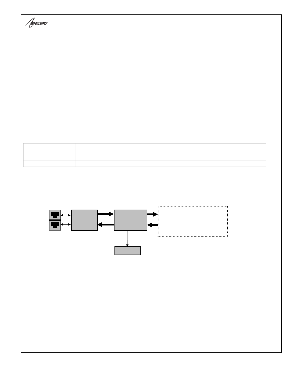
The following is a block diagram of the ASI2416. Different models will have different configurations of the audio I/O,
per the above table.
Figure 1. ASI2416 block diagram.
10.1 CobraNet™
CobraNet™ is a combination of software, hardware and network protocol that allows distribution of many channels of
real-time, high quality, digital audio over an Ethernet network. It was developed by Peak Audio in the 1990s and is
now owned by Cirrus Logic. Interoperability between CobraNet devices from different manufacturers is supported
through a standard communications protocol. CobraNet compliant devices are based on a common silicon or
hardware reference design from Cirrus Logic.
The Cirrus Logic website, www.cobranet.info, is dedicated to CobraNet.
100Mbps
Ethernet
Primary
RJ-45
Texas Instruments
TMS320C6713
DSP
100Mbps
Ethernet
Secondary
Display
CobraNet Audio
Routing Channels
33-48
CobraNet Audio
Routing Channels
1-16
A
udio I/O
(depends on model)
CS181022
CobraNet
interface

ASI2416
www.audioscience.com 12 18 November 2008
CobraNet delivers audio in standard Ethernet packets over 100Mbit Fast Ethernet. Switches, hubs, media converters,
and other gear that operate in compliance with the IEEE 802.3u specification for Fast Ethernet, will work with
CobraNet. CobraNet does not support 10Mbit Ethernet varieties (10BASE-T, Coaxial) due to their limited bandwidth.
CobraNet operates at the Data Link Layer (also referred to as OSI Layer 2 or MAC layer). Because it does not use the
higher IP layer for audio data transport, CobraNet does not suffer from IP latency limitations. In most cases data
communications and CobraNet data can coexist on the same network without QOS issues. All audio is sent inside a
custom Ethernet packet whose header tells network devices that the packet contains CobraNet audio, rather than
plain data. The CobraNet term for an audio packet is "bundle". A bundle may contain from one to eight audio
channels, each channel being composed of PCM samples of 16, 20 or 24 bits in length.
10.2 CobraNet Routing
The whole point of network audio is to route digital audio from point A to point B. CobraNet introduces a concept
called a “bundle” to define virtual audio routes from one CobraNet device to another one. A bundle is a logical
collection of up to 8 channels that can be sent from on device to another. Each bundle is assigned a unique number
between 1 and 65535. Bundles form the heart of the CobraNet routing capability.
CobraNet
Device 2
The bundle number 300 is used to describe this collection of channels
coming from Device 1. s1 to s8 represent audio samples. The bundle
shown above consists of 1 to 8 samples of audio each taken from
different channels of Device 1.
CobraNet
Device 1
Bundle #300
s1,s2,s3,s4,s5,s6,s7,s8
Figure 2. Illustration of a CobraNet bundle going between 2 CobraNet devices.
The above figure illustrates a bundle of audio being sent from one CobraNet device to another. Device 1 is
transmitting the CobraNet bundle, while Device 2 is receiving it. In this case, both devices need to be set to bundle
300 for the audio link to be made. The CobraNet mechanism for transmitting bundles is “transmitters.” Similarly, the
mechanism for receiving bundles is “receivers.” Each CobraNet device has several transmitters and receivers and so
can simultaneously send and receive audio channels using several different bundle numbers. This capability supports
audio links between many different CobraNet devices.
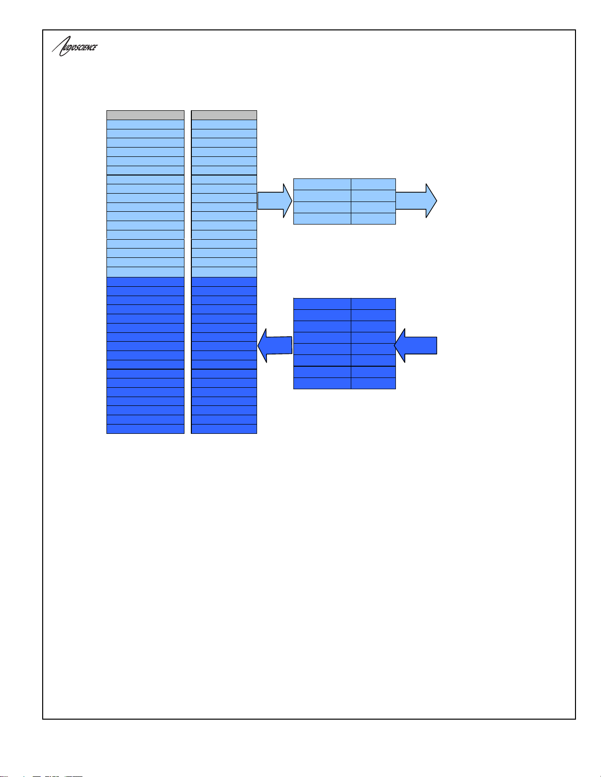
10.2.1 Audio Routing Channels
Before further discussion of CobraNet transmitters and receivers, terminology useful for specifying audio channels
within a bundle needs to be introduced. Somewhat obviously, these channels are called the Audio Routing Channels.
On an ASI2416 audio routing channels 1 – 16 map to input channels 1 – 16. Similarly, on the output side audio
routing channels 33-48 map to output channels 1 –16.
ASI2416
www.audioscience.com 13 18 November 2008
CobaraNet_Ch 1
CobaraNet_Ch 2
CobaraNet_Ch 3
CobaraNet_Ch 4
CobaraNet_Ch 5
CobaraNet_Ch 6
CobaraNet_Ch 7
CobaraNet_Ch 8
CobaraNet_Ch 9
CobaraNet_Ch 10
CobaraNet_Ch 11
CobaraNet_Ch 12
CobaraNet_Ch 13
CobaraNet_Ch 14
CobaraNet_Ch 15
CobaraNet_Ch 16
CobaraNet_Ch 33
CobaraNet_Ch 34
CobaraNet_Ch 35
CobaraNet_Ch 36
CobaraNet_Ch 37
CobaraNet_Ch 38
CobaraNet_Ch 39
CobaraNet_Ch 40
CobaraNet_Ch 41
CobaraNet_Ch 42
CobaraNet_Ch 43
CobaraNet_Ch 44
CobaraNet_Ch 45
CobaraNet_Ch 46
CobaraNet_Ch 47
CobaraNet_Ch 48
0 (silence)
1
2
3
4
5
6
7
8
9
10
11
12
13
14
15
16
17-32 unused
33
34
35
36
37
38
39
40
41
42
43
44
45
46
47
48
49-64 unused
Audio Routing Channels
txSubMap Tx1
txSubMap Tx2
txSubMap Tx3
txSubMap Tx4
rxSubMap Rx1
rxSubMap Rx2
rxSubMap Rx3
rxSubMap Rx4
rxSubMap Rx5
rxSubMap Rx6
rxSubMap Rx7
rxSubMap Rx8
Transmit bundles are
sent out on Ethernet
Receive bundles are
received from Ethernet
CobraNet audio channel used in
transmitters and receivers.
ASI2416
labels
Figure 3. Audio routing channel details.
10.2.2 CobraNet Transmitters
A CobraNet transmitter is a logical entity in the CobraNet interface that has the ability to send a bundle of audio
samples on the CobraNet network. CobraNet devices typically have multiple transmitters. The ASI2416, for example,
has 4 transmitters. An incomplete list of transmitter routing variables follows:
• txBundle – this variable specifies the bundle number to transmit. A value of 0 indicates that the transmitter is
disabled.
• txSubMap – a sequence of up to 8 audio routing channel numbers that specify which audio samples should
be placed in the bundle. A value of 0 indicates an unused slot in the bundle.
• txSubFomat – a sequence of format specifiers that define how many bits per sample are placed in the bundle.
• txSubCount – the number of channels in this bundle.

ASI2416
www.audioscience.com 14 18 November 2008
10.2.3 CobraNet Receivers
A CobraNet receiver is a logical entity in the CobraNet interface that has the ability to receiver a bundle of audio
samples from the CobraNet network. CobraNet devices typically have multiple receivers. The ASI2416, for example,
has 4 receivers. An incomplete list of receiver routing variables follows:
• rxBundle – the number of the bundle to receive. This should be the same bundle number being transmitted
somewhere else on the network. A value of 0 indicates that the receiver is disabled.
• rxSubMap – a sequence of up to 8 audio routing channel numbers that specify where incoming bundle
samples should be routed.
10.2.4 CobraNet Sample Rate and Latency
The CobraNet sample rate supported by the ASI2416 is fixed at 48kHz with three latency modes of 5.33ms (default),
2.67ms, or 1.33ms.
10.2.5 CobraNet References
This document is not intended to be an expansive guide to CobraNet networking and routing. The ASI2416 adheres
to the CobraNet standard through the use of off-the-shelf CobraNet silicon from Cirrus Logic. More detailed CobraNet
information is available from Cirrus Logic’s website.
The following links may be helpful:
CobraNet Info:
http://www.cobranet.info/en/support/cobranet/
CobraNet CobraCAD and CobraNet Discovery:
http://www.cobranet.info/dispatch/forms/sup/boardreg/breg/BregController.jpf
CobraNet Audio Routing Primer:
http://cirrus.com/en/pubs/appNote/CobraNet_AudioRoutingPrimer.pdf
Hardware Manual and Programmer’s Reference:
http://www.cobranet.info/en/support/cobranet/developer/tech_data_sheet.html
ASI2416
www.audioscience.com 15 18 November 2008
11 HARDWARE INSTALLATION
11.1 Rack Mounting
The ASI2416 is 1 RU (1 rack unit/space) high and mounts in a standard 19-inch equipment rack.
• Use four mounting screws to fasten the front panel of the ASI2416 to the 19-inch rack rails.
• Support any cables that are attached to the back of the ASI2416 so that their weight does not put undue
stress on the ASI2416’s connectors.
• The ASI2416 has cooling vents on the side of the unit. Be careful not to obstruct these.
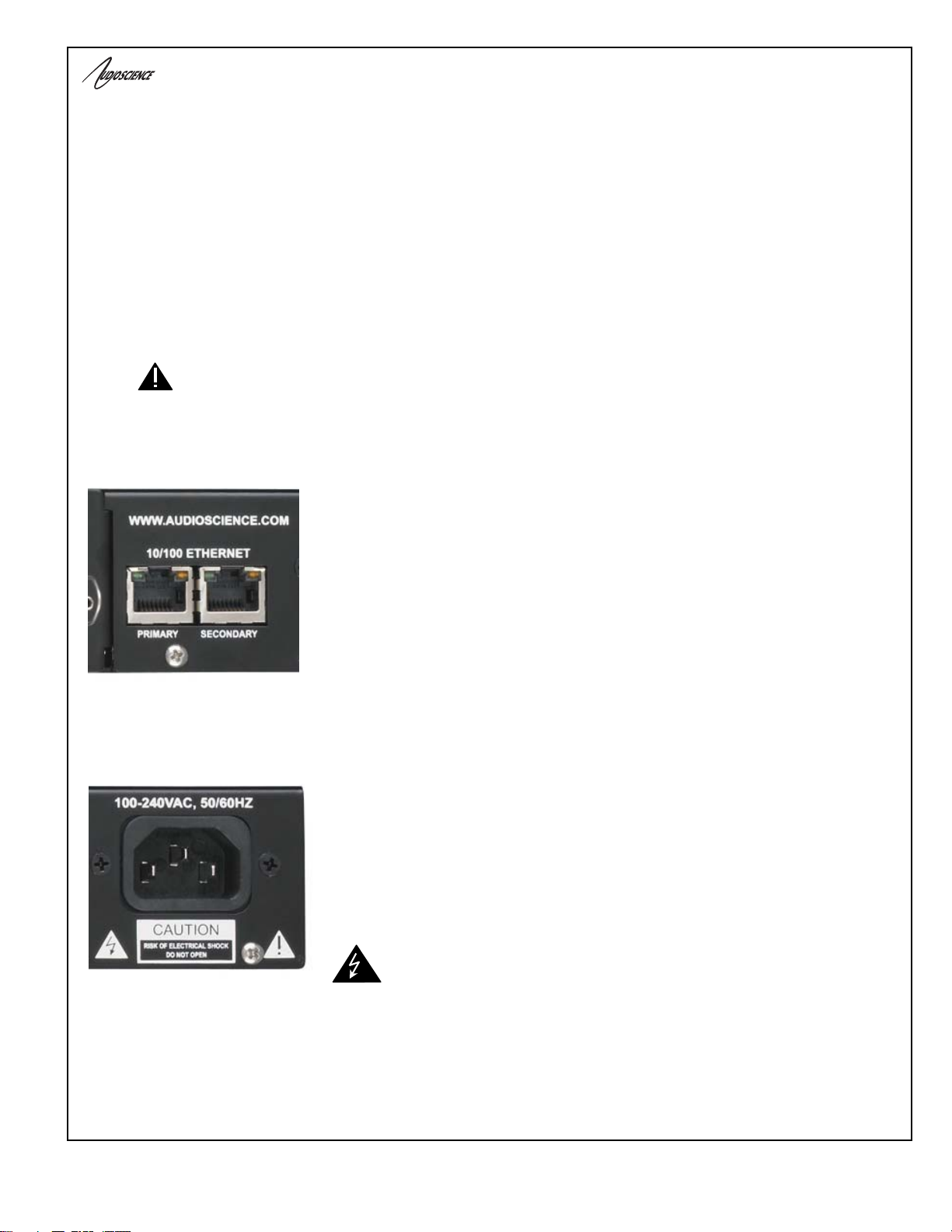
11.2 Ethernet Connection
There are two RJ-45 Ethernet jacks on the rear of the ASI2416. If a redundant
CobraNet network is not being used then plug a network cable into the PRIMARY
jack. If a redundant network is being used then plug a second network cable into
the SECONDARY jack.
A CAT-5 or better (CAT-5e, CAT-6 etc) network cable is required for 100baseT
Ethernet operation. The cable length between the ASI2416 and a network switch
should not exceed 100 meters (328 feet)
11.3 AC Power
The detachable AC power cord that comes with the ASI2416 plugs into the IEC
connector on the chassis.
The ASI2416 operates with AC voltages from 90 to 260VAC, 47 to 63Hz. No
selection of voltage or frequency is required, the ASI2416’s power supply will
automatically adjust.
Use only an AC power source with a protective earth ground.
The ASI2416 has no power switch. Detach the AC power cord to
remove power to the ASI2416.

ASI2416
www.audioscience.com 16 18 November 2008
11.4 Modules and Audio Connections
11.4.1 Modules
The ASI2416 will ship with ordered modules and connectors already installed. Should a module need to be changed
in the field, it is easily done. Use an anti-static strap when handling the modules. Power down the ASI2416 and
remove the three, small screws that attach the module to the ASI2416 (two on the bottom, one on top). Slide the
module(s) out. Slide the module(s) in the desired slot(s), replace the three screws, and power up the ASI2416. The
connector is removed from the module in the same way; slide the two components apart.
Note that when installing modules, always populate the back of the ASI2416 from left to right, and do not leave any
gaps.
For Example, looking at the back of an ASI2416:
Correct:
ASI1443 ASI1443 ASI1431 <empty>
Incorrect:
ASI1443 <empty> ASI1431 <empty>
There are seven different modules for the ASI2416:
ASI1431 – Analog, 8 channels in/out
ASI1432 – Analog, 8 channels in
ASI1433 – Analog, 8 channels out
ASI1441 – AES/EBU, 4 in/out (8 channels in/out)
ASI1442 – AES/EBU, 4 in (8 channels in)
ASI1443 – AES/EBU, 4 out (8 channels out)
ASI1451 – GPIO, 16 Optos/16 Relays
For further information on the modules, datasheets for each one can be found here under Resources.
11.4.2 Connectors
The ASI2416 modules support a range of interchangeable I/O connectors. A choice of 50pin Centronics (ASI1491),
StudioHub+TM (ASI1492), or Phoenix (ASI1493) allows the module to adapt to a wide variety of interconnection
schemes with minimal custom wiring.
The ASI2416 will ship with the ordered connectors installed on the ordered modules. Should a connector need to be
replaced in the field, remove the module as stated in the section above then grasp the module in one hand and the
connector in the other and carefully slide the two pieces apart. Replace connectors as needed, and then slide the
module/connector unit back in the ASI2416, as stated above.
Refer to the rear label of the connector, or the module’s datasheet listed here under Resources, for pinout information.
ASI1491
50
p
in Centronics ASI1492
StudioHub+ ASI1493
Terminal Block

ASI2416
www.audioscience.com 17 18 November 2008
12 OPERATION
12.1 Power up sequence
This section describes the ASI2416 power up sequence.
12.1.1 AC Power
Connect AC power to the unit by attaching the power cord to the IEC connector on the rear of the ASI2416, as
explained in section 12.4
12.1.2 Firmware images
The ASI2416 boots from a firmware image stored in flash memory. There are two independent firmware images
stored in every ASI2416. The two images are named “factory” and “update”. The “factory” image is a reference image
that is in place should a “bad” image be downloaded to the device. The “update” image is the image that can be
updated in the field if required.
12.1.3 Firmware loading sequence
When first powered up, the ASI2416 performs the following sequence:
1. Checks for a valid “update” firmware image.
2. Loads the update image and starts running it.
3. Loads any control settings that may have been stored to flash.
In the case where the “update” image is determined to be corrupt, the factory image is loaded.
12.1.4 Loading the factory firmware image
The ASI2416 can be forced to load the factory firmware image by depressing the SELECT button on front panel as
power is applied to the device. Keep button depressed while power is applied.
12.2 Front Panel Display
The ASI2416 display shows status readings from the ASI2416. The select button should be pressed to move to the
next display. In order the displays are:
ASI2416
www.audioscience.com 18 18 November 2008
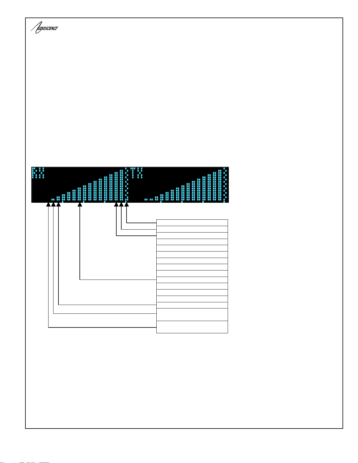
12.2.1 CobraNet Transmit and Receive Peak Meters Display
The first display shows peak meters for all 16 CobraNet receive and transmit routing channels
Peak Meter features:
• Ticks extending from the baseline to the bottom of the display mark every 4th peak meter, i.e. channels 4,8,12, and 16 are
marked.
• A "checkered" bar indicates a peak level of -2dBFS or greater.
• Meter bars are 2 pixels wide.
• A missing bar on a receive channel indicates no CobraNet audio connect.
• A 1 pixel high bar indicates CobraNet audio connect, but audio level is below -40 dBFS.
• A 2 pixel high bar indicates CobraNet audio connect and an audio level greater that -40 dBFS but less than –35 dBFS.
• Audio peak levels in the range of -40 dBFS to -20 dBFS are displayed using 5 dB per pixel.
• Audio peak levels in the range of -20 dFS to 0 dBFS are displayed starting at 6 pixels high and use addition pixels at a
rate of 1 pixel very 2 dB.
Figure 4. ASI2416 display of CobraNet peak meters and bar height mapping to dBFS range.
-2 dBFS <= X <=0 dBFS
-4 dBFS <= X <-2 dBFS
-6 dBFS <= X <-4 dBFS
-8 dBFS <= X <-6 dBFS
-10 dBFS <= X <-8 dBFS
-12 dBFS <= X <-10 dBFS
-14 dBFS <= X <-12 dBFS
-16 dBFS <= X <-14 dBFS
-18 dBFS <= X <-16 dBFS
-20 dBFS <= X <-18 dBFS
-25 dBFS <= X <-20 dBFS
-30 dBFS <= X <-25 dBFS
-35 dBFS <= X <-30 dBFS
-40 dBFS <= X <-35 dBFS
X < -40dBFS, CobraNet Rx
audio connect
X < -40 dBFS, CobraNet Rx
no connect
In the above table X is a
peak meter reading in
dBFS.

ASI2416
www.audioscience.com 19 18 November 2008
12.2.2 CobraNet Bundle Number and Channel Settings Display
The bundle panels support displaying bundle and submap information for the device’s active CobraNet transmitters
and receivers. By default receivers 1 & 2 are displayed and transmitters 1 & 2 are displayed. Additional transmitters
and receivers are displayed if they have been assigned a non-zero bundle number indicating that they are active.
Figure 5. ASI2416 bundle display for CobraNet receivers 1 and 2.
In Fig. 7, the first receiver’s submap is specifying the first sub-channel get output on audio routing channel 33. On an
ASI2416-1100 (analog, 16 I/O), this corresponds to Line Out 1. The second sub-channel is output on Line Out 2 and
so on. In this instance receiver 1 is taking in all 8 channels of bundle 400 and outputting them to Line Outs 1..8.
12.2.3 MAC and IP Address Display
This display shows the ASI2416s network MAC address and IP address. If the IP address has been assigned
dynamically then DYNAM is displayed. If has been assigned statically then STATIC is shown.
Figure 6. ASI2416 MAC and IP address display.
Rx indicates
a CobraNet
receiver.
This column
shows the
receiver
in
de
x.
The bundle
number
assigned the
r
ece
iv
e
r.
Each bundle can specify up to
8 audio routing channels. In
this case 33…40 for bundle
4
00
a
n
d
41…4
8
f
o
r
bu
n
d
l
e
4
0
1
ASI2416
www.audioscience.com 20 18 November 2008
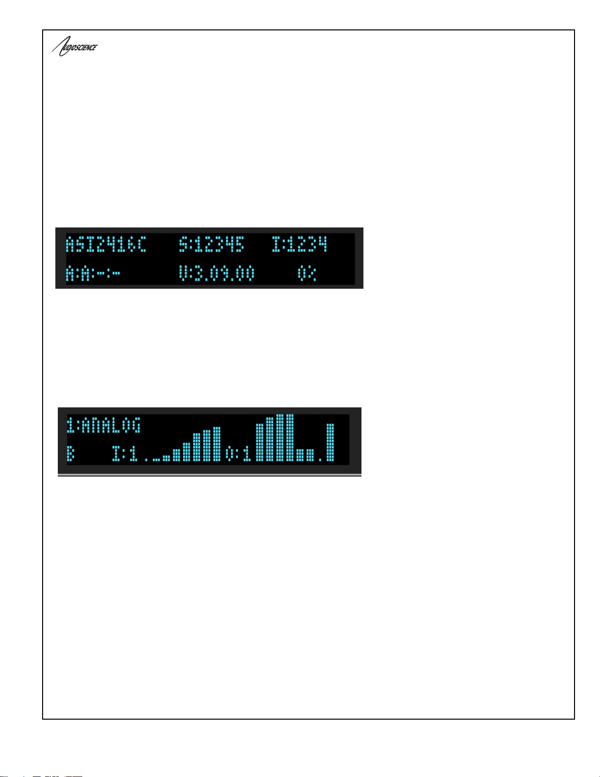
12.2.4 Product Information Display
This display shows, top line, from left to right:
• Part number and revision (ASI2416C)
• Serial number (S:12345)
• Adapter index (I:1234)
•
This display shows, bottom line, from left to right:
• Installed modules: A=Analog, D=AES/EBU Digital (A:A:-:-).
• DSP firmware version (V:3.09.00)
• DSP utilization in %
Figure 7. ASI2416 product information display.
12.2.5 Module Input/output Meters – Analog Display
This display shows information and peak meters for an analog module's 8 input and outputs. The meters have the
same scale as the CobraNet Transmit and Receive peak meters
Figure 8. ASI2416 analog module display.
Peal Meter Features:
• A "checkered" bar indicates a peak level of -2dBFS or greater.
• Meter bars are 2 pixels wide.
• A missing bar on a receive channel indicates no CobraNet audio connect.
• A 1 pixel high bar indicates the audio level is below -40 dBFS.
• A 2 pixel high bar indicates an audio level greater that -40 dBFS but less than –35 dBFS.
• Audio peak levels in the range of -40 dBFS to -20 dBFS are displayed using 5 dB per pixel.
• Audio peak levels in the range of -20 dFS to 0 dBFS are displayed starting at 6 pixels high and use addition pixels at a
rate of 1 pixel very 2 dB.
Table of contents
Other AudioScience Recording Equipment manuals


