AudioScience Hono AVB 4.4M User manual
April 14, 2015
www.audioscience.com Jan 16 2015
AVB 4.4M/4.4D/2.2M/2.2D
FOUR OR TWO CHANNEL MIC/LINE/AES AVB INTERFACES
1 DESCRIPTION
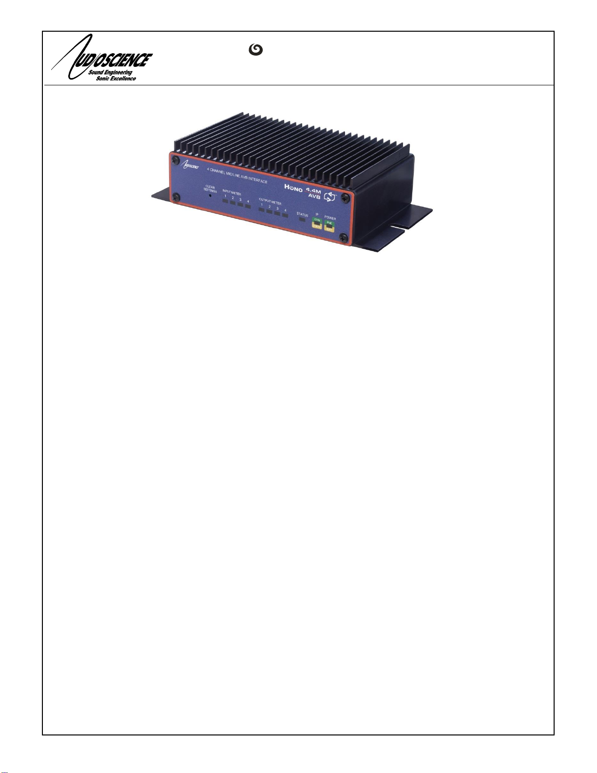
The Hono AVB 4.4M, 4.4D, 2.2M and 2.2D are AVB interface in the Hono Mini series designed for use in the professional
installed sound market. The Hono AVB 4.4M and 2.2M receive 4 channels of AVB and sends them to 4 balanced analog audio
outputs (2 on the 2.2M), while simultaneously inputting 4 channels (2 on the 2.2M) of mic/line level balanced audio and
transmitting them as 4 channels of AVB. The Hono AVB 4.4D and 2.2D receive 4 channels of AVB and sends them to 4
AES/EBU audio outputs (2 on the 2.2D), while simultaneously inputting 4 channels (2 on the 2.2D) of AES/EBU audio and
transmitting them as 4 channels of AVB. The Hono AVB Minis are perfect for applications requiring additional inputs or outputs
in an existing AVB system.
2 FEATURES
Inputs
4 (4.4M) or 2 (2.2M) balanced analog mic/line inputs
4 (4.4D) or 2 (2.2D) AES/EBU inputs
Software adjustable, non-volatile, input levels from –60 to
+24dBu
100dB DNR, -90dB THD+N, -110dBu EIN
Software selectable 48V phantom power individually
available on all inputs
3.81mm pluggable terminal block connectors
Outputs
4 (4.4M) or 2 (2.2M) balanced analog line outputs
4 (4.4D) or 2 (2.2D) AES/EBU outputs
Software adjustable, non-volatile output levels from -10
to +24dBu
GPIO
Four opto-isolated inputs
Four normally open relay isolated outputs
DSP
Peak and RMS meters on all audio inputs and outputs
Mixing of any input to any output
AVB
Protocols: IEEE1722, IEEE1722.1, IEEE802.1AS,
IEEE802.1Q FQTSS, IEEE802.1Q MSRP, IEEE802.1Q
MVRP
Four channels of AVB in and out
Media clock input and output streams
AVnu Alliance certified
Power
Power over Ethernet (PoE) 802.3af compliant
External +5V power supply if POE not being used
Chassis
Rack mountable using optional 1U front panel
Wings allow easy mounting
5.25 inches W x 3.125 inches L x 1.37 inches H
Control
All settings adjustable from ASIControl software
3 ARCHITECTS AND ENGINEERS SPECIFICATION
The AVB interface shall provide microphone/line balanced analog audio inputs and line level analog audio outputs or
AES/EBU inputs and outputs on plug in terminal block connectors. 48V DC Phantom power shall be provided on each mic/line
input. Analog-to-digital and digital-to-analog conversion shall be 24bit at a 48kHz sample rate. The AVB interface shall provide
front panel meters to monitor the analog input and output signals. Four channels of input and output shall be provided on an
RJ-45 connector. The AVB interface shall be compatible with the AudioScience ASIControl software and 3rd party IEEE1722.1
controller software for configuration and monitoring. The AVB interface shall be powered by IEEE 802.3af Power-over-
Ethernet or from an external +5VDC @ 10W power supply. The AVB interface shall be compliant with CE, FCC part 48 and
the RoHS directive. Warranty shall be 3 years.
NOH ™

Hono AVB 4.4M/4.4D/2.2M/2.2D
www.audioscience.com
2
14-Apr-15
4 SPECIFICATIONS
AVB INPUT/OUTPUT
Type
100BaseT Ethernet
Connector
RJ-45
Streams
Four input and four output, Media clock stream input and output
Stream formats
IEEE 1722-2011/IEC 61883-6/AM824/MBLA mono channel
Sample Rate
48kHz (96kHz to be added in future, software updatable)
Latency
TBD
Control Protocol
IEEE1722.1 -2013 and AudioScience HPI
MICROPHONE/LINE INPUT
Type
Balanced
Connector
Terminal block
Input Level
-60 to +24dBu in 1dB increments
Input Impedance
5Kbalanced
Phantom Power
48V @ 5mA max per input, software selectable on each input; on and off
Dynamic Range [1]
>100dB
THD+N [2]
< -90dB
EIN [3]
–100dBu
A/D converter
24bit Over sampling
Frequency Response
20Hz to 20kHz +/-3dB
ANALOG OUTPUT
Type
Balanced
Connector
Terminal block
Output Level
-10 to +24dBu in 1dBu steps
Load Impedance
-10 to +14dBu:600 ohms or greater
15dBu to +24dBu: 2K ohms or greater
Dynamic Range[1]
>100dB
THD+N[2]
<-90dB
Frequency Response
20Hz to 20kHz +/-3dB
LATENCY (48kHz AVB)
Analog input across network to Analog out
TBD
AVB input to Analog Out
TBD
Analog input to AVB output
TBD
Analog input to Analog output
TBD
GP OPTO-ISOLATED INPUTS
Isolation
2000VRMS
Input Drive
4mA typical with internal 5V supply and internal 1K current limiting resistor
Network protocol
AudioScience HPIUDP
GP RELAY OUTPUTS
Isolation
1500VRMS between relay contacts and coil
Contact Rating
Up to 220VDC/250VAC and 2A, 60W maximum
Network protocol
AudioScience HPIUDP
SYSTEM REQUIREMENTS
Network switch
AVnu certified network switch with AVB support. Compatible switches are: Extreme X430, X440
and x460 switches with AVB license installed and firmware v15.5.3.4 or greater.
GENERAL
Dimensions
6.50"W x 3.125”D x 1.90"H (165mm x 80mm x 48mm)
Weight
24oz, 710g
Operating Temperature
0C to 45C ambient, assuming still air.
Power Requirements
IEEE 802.3af Power-over-Ethernet Class 0 or External +5VDC @ 2A power supply (supplied)
Certifications
CE: EN55103 FCC: Part 15 Subpart B Class A
[1] –Dynamic range measured with a –60dBFs sine wave and A weighting filter and 20-20kHz b/w
[2] - THD+N measured using a +20dBu 1kHz sine wave sampled at 48kHz, 20-20kHz b/w and A weighting filter
[3] - With Zs = 150ohms and Input level set to –10dBu
Hono AVB 4.4M/4.4D/2.2M/2.2D
www.audioscience.com
3
14-Apr-15
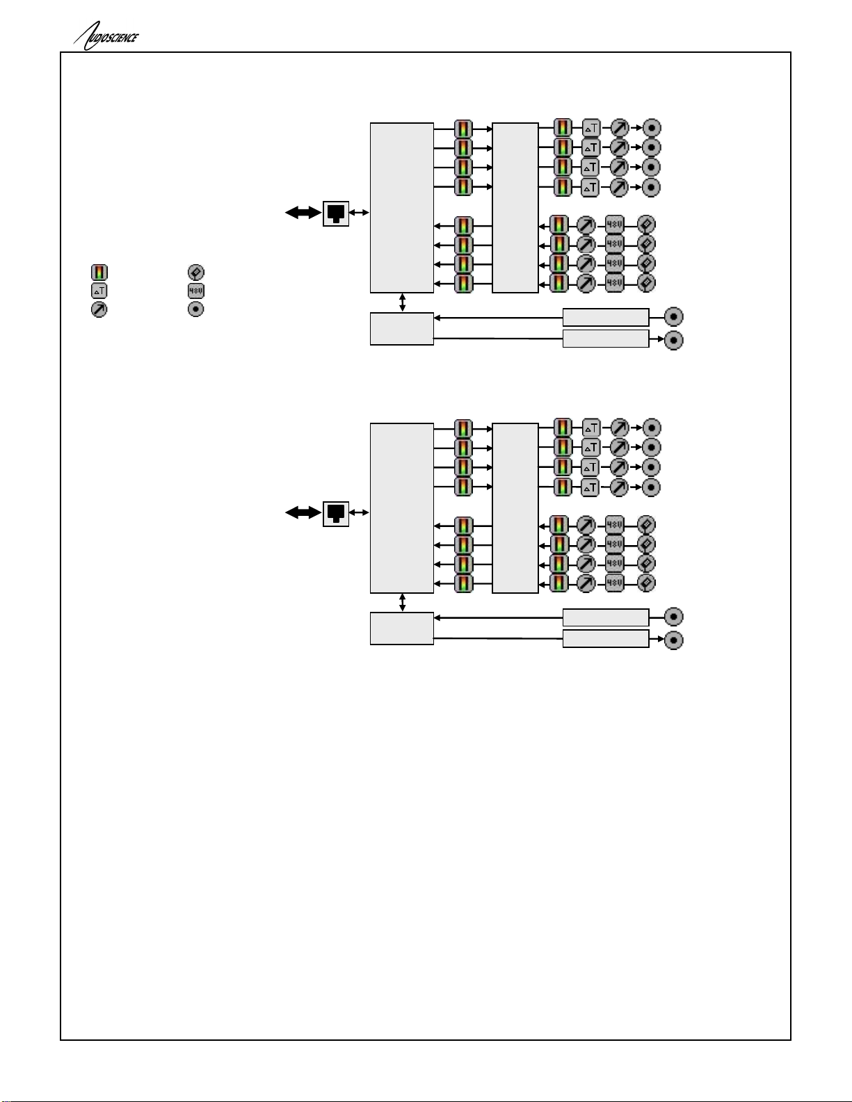
100Mbps
Ethernet
RJ-45
4x4
AVB
Interface
Mixing
Matrix
GPIO Relays (x4)
GPIO Optos (x4)
HPIUDP
Interface
Relays
Opto-isolators
Line Out 3*
Line Out 2
Line Out 1
Line Out 4*
Mic/Line In 2
Mic/Line In 3*
Mic/Line In 4*
Mic/Line In 1
*4.4M only
100Mbps
Ethernet
RJ-45
4x4
AVB
Interface
Mixing
Matrix
GPIO Relays (x4)
GPIO Optos (x4)
HPIUDP
Interface
Relays
Opto-isolators
AES/EBU In 2
AES/EBU In 3*
AES/EBU In 4*
AES/EBU In 1
AES/EBU Out 1
AES/EBU Out 2
AES/EBU Out 3*
AES/EBU Out 4*
*4.4D only
5 BLOCK DIAGRAM
5.1 Hono AVB 4.4M and 2.2M
5.2 Hono AVB 4.4D and 2.2D
Key:
Input/Output
Level
Meter
Time Delay
Mic Input
Phantom Power

Hono AVB 4.4M/4.4D/2.2M/2.2D
www.audioscience.com
4
14-Apr-15
6 REVISIONS
Date
Description
November 22 2013
Preliminary
November 26 2013
Update
December 17 2013
Created 2.2M doc
February 7 2014
Added AVB gPTP section
July 15 2014
Updated gPTP section
January 15 2015
Added “System Requirements” section to specs page
January 15 2015
Expanded to include all AVB Mini models
January 16 2015
New picture on page 1
April 14 2015
Added description for AVB_In controls

Hono AVB 4.4M/4.4D/2.2M/2.2D
www.audioscience.com
5
14-Apr-15
7 CONTENTS
1DESCRIPTION....................................................................................................................................................1
2FEATURES .........................................................................................................................................................1
3ARCHITECTS AND ENGINEERS SPECIFICATION .........................................................................................1
4SPECIFICATIONS ..............................................................................................................................................2
5BLOCK DIAGRAM .............................................................................................................................................3
5.1 HONO AVB 4.4M AND 2.2M........................................................................................................................................3
5.2 HONO AVB 4.4D AND 2.2D .........................................................................................................................................3
6REVISIONS.........................................................................................................................................................4
7CONTENTS.........................................................................................................................................................5
8TABLE OF FIGURES .........................................................................................................................................6
9IMPORTANT SAFETY INSTRUCTIONS............................................................................................................7
10 NOTICES.............................................................................................................................................................8
INTRODUCTION........................................................................................................................................................9
11 FRONT AND BACK PANELS ............................................................................................................................9
11.1 FRONT PANEL...............................................................................................................................................................9
11.1.1 POWER LED .......................................................................................................................................................9
11.1.2 IP LED.................................................................................................................................................................9
11.1.3 STATUS LED.....................................................................................................................................................10
11.1.4 METER LEDS....................................................................................................................................................10
11.2 BACK PANELS.............................................................................................................................................................10
11.2.1 OUT 1..4 ............................................................................................................................................................11
11.2.2 IN 1..4 ................................................................................................................................................................11
11.2.3 GPIO –RELAYS ................................................................................................................................................11
11.2.4 GPIO-OPTOS ....................................................................................................................................................11
11.2.5 RJ45 –PRIMARY+PoE.....................................................................................................................................11
11.2.6 5V DC Jack........................................................................................................................................................11
12 HARDWARE INSTALLATION......................................................................................................................... 11
12.1 MOUNTING .................................................................................................................................................................11
12.1.1 Flange Mounting................................................................................................................................................11
12.1.2 Rack Mounting...................................................................................................................................................11
12.2 ETHERNET CONNECTION ............................................................................................................................................11
12.2.1 PoE Power.........................................................................................................................................................12
12.2.2 External +5V Power ..........................................................................................................................................12
13 OPERATION .................................................................................................................................................... 12
13.1 POWER UP SEQUENCE .................................................................................................................................................12
13.1.1 Power.................................................................................................................................................................12
13.1.2 Firmware images...............................................................................................................................................12
13.1.3 Firmware loading sequence...............................................................................................................................12
13.1.4 Loading the factory firmware image..................................................................................................................12
14 CONFIGURATION........................................................................................................................................... 12
14.1 ASICONTROL CONFIGURATION..................................................................................................................................12
14.1.1 ASIControl Layout .............................................................................................................................................13
14.1.2 About..................................................................................................................................................................13
14.1.3 AVB....................................................................................................................................................................14
14.1.4 Status..................................................................................................................................................................16
14.1.5 Level...................................................................................................................................................................16
14.1.6 Meter..................................................................................................................................................................17
14.1.7 AES/EBU I/O .....................................................................................................................................................17

Hono AVB 4.4M/4.4D/2.2M/2.2D
www.audioscience.com
6
14-Apr-15
14.1.8 Input and Output Volume Adjustment................................................................................................................18
14.1.9 Audio Delay –Future feature ............................................................................................................................18
14.1.10 Signal Generator............................................................................................................................................18
14.2 MIC/LINE INPUT CONFIGURATION...............................................................................................................................19
14.2.1 Phantom Power..................................................................................................................................................20
14.2.2 Input Level .........................................................................................................................................................20
14.3 ACCESS CONTROL USING PASSWORDS –FUTURE FEATURE .........................................................................................20
14.4 GPIO..........................................................................................................................................................................22
14.4.1 Outputs...............................................................................................................................................................22
14.4.2 Inputs .................................................................................................................................................................23
8 Table of Figures
Figure 1. ASIControl layout .................................................................................................................................... 13
Figure 2. Adapter About information seen in right side of ASIControl.................................................................... 13
Figure 3. The Status user interface ........................................................................................................................ 16
Figure 4. Using ASIControl to select Analog_Out 1 ............................................................................................... 16
Figure 5. Level displayed by ASIControl for Line_Out 1 ........................................................................................ 16
Figure 6. A stereo peak meter display; RMS is green and peak is yellow ............................................................. 17
Figure 7. ASIControl node displays with volumes.................................................................................................. 18
Figure 8 Using ASIControl to select Analog_Out 1 ................................................................................................ 18
Figure 9 Audio Delay displayed in right pane of ASIControl for Line_Out 1 .......................................................... 18
Figure 10. Internal nodes as seen in ASIControl.................................................................................................... 19
Figure 11. Signal Generator User Interface as seen in ASIControl ....................................................................... 19

Hono AVB 4.4M/4.4D/2.2M/2.2D
www.audioscience.com
7
14-Apr-15
9 IMPORTANT SAFETY INSTRUCTIONS
1. Read these instructions.
2. Keep these instructions.
3. Head all warnings.
4. Follow all instructions.
5. Do not use this apparatus near water.
6. Clean only with a dry cloth.
7. Do not block any ventilation openings. Install in accordance with these instructions.
8. Do not install near any heat sources such as radiators, heat registers, stoves, or other apparatus
(including amplifiers) that produce heat.
9. Protect the power supply cord from being walked on or pinched, particularly at plug ends, convenience
receptacles, and the point where they exit from the apparatus.
10. Only use attachments/accessories specified by the manufacturer.
11. Unplug this apparatus during lightning storms or when unused for long periods of time.
12. Refer all servicing to AudioScience. Servicing is required when the apparatus has been damaged in any
way, such as power-supply cord or plug is damaged, liquid has been spilled or objects have fallen into the
apparatus, the apparatus has been exposed to rain or moisture, does not operate normally, or has been
dropped.

Hono AVB 4.4M/4.4D/2.2M/2.2D
www.audioscience.com
8
14-Apr-15
10 NOTICES
FEDERAL COMMUNICATIONS COMMISSION (FCC) INFORMATION
NOTE: This equipment has been tested and found to comply with the limits for a Class A digital device, pursuant to Part
15 of the FCC Rules. These limits are designed to provide reasonable protection against
harmful interference in a commercial installation. This equipment generates, uses, and can radiate radio frequency
energy and, if not installed and used in accordance with the instructions, may cause harmful interference to radio
communications. Operation of this equipment in a residential area is likely to cause harmful interference, in which case
the user will be required to correct the interference at his or her own
expense.
Hono AVB 4.4M/4.4D/2.2M/2.2D
www.audioscience.com
9
14-Apr-15
INTRODUCTION
The Hono Mini AVB Mini series of products are AVB™audio interfaces providing 4 channels of AVB receive and
transmit.
Various models provide up to 4 channels of microphone/line in and line out or up to 4 channels of AES/EBU I/O.
Each input and output is configured with a pluggable terminal block (Phoenix type) connector).
Additionally each model contains GPIO. The GPIO inputs are opto-isolated and the GPIO outputs are relay
based.
The Hono Mini AVB Mini interfaces features a powerful Texas Instruments 32bit floating point DSP that allows
sophisticated switching and mixing. LED displays on the unit’s front panel show peak meters and AVB status.
The units maybe powered using Power-over-Ethernet (PoE) from the Ethernet port or from an external +5V power
supply.
AudioScience provides application software that may be used to set up the Hono Mini AVB Mini interfaces.
ASIControl can be used to set all internal features of the unit (such as levels).
The following table lists the Hono Mini AVB Series and a description of each unit.
Model
Network
Protocol
Description
Hono Mini AVB 2.2M
AVB
2 channels of balanced analog mic/line inputs, line outputs
Hono Mini AVB 4.4M
AVB
4 channels of balanced analog mic/line inputs, line outputs
Hono Mini AVB 2.2D
AVB
2 channels of AES/EBU inputs/outputs
Hono Mini AVB 4.4D
AVB
4 channels of AES/EBU inputs/outputs
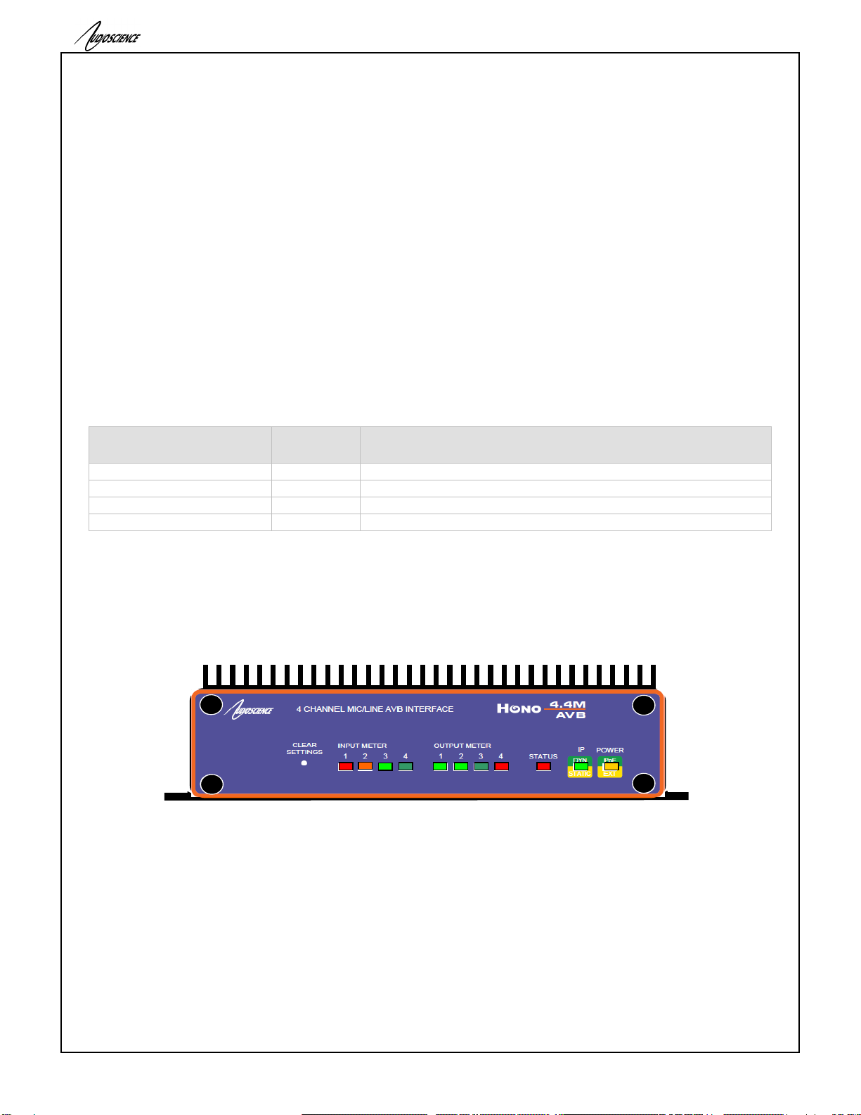
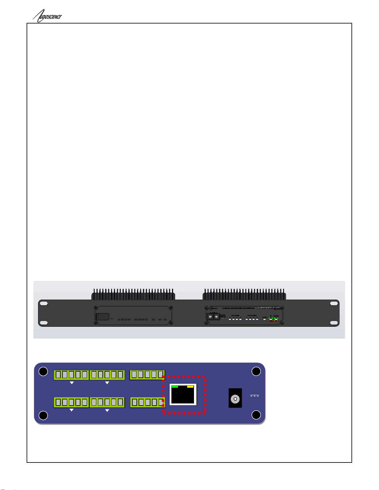
11 FRONT AND BACK PANELS
11.1 Front Panel
The following diagram shows the front panel of the 4.4M. The 2.2M, 2.2D and 4.4D are similar, except that the
2.2M & 2.2D only have two input and two output meters.
11.1.1 POWER LED
Green when running from Power over Ethernet (PoE). Note, PoEis only available from the primary RJ45.
Orange when running from the external +5V DC source.
Orange + Green when both present.
11.1.2 IP LED
Green when an IP address has been obtained from a DHCP server or from autoip.
Orange when a static IP address is configured.
Orange Blinking when the unit does not have an IP address.
ASI2314, Hono AVB 4.4M
RS-232
INPUT METER
1 2 3 4
CLEAR
SETTINGS
4 . 4 M
CO B R A NET
ADAPTER ID
OUTPUT METER
1 2 3 4
STATIC
DYN
4 CHANNEL MIC/LINE COBRANET INTERFACE
EXT
PoE
IP
POWER
STATUS
HONO
Hono AVB 4.4M/4.4D/2.2M/2.2D
www.audioscience.com
10
14-Apr-15
11.1.3 STATUS LED
Green when everything is OK.
Orange when the unit is running from its factory (backup) firmware.
Red Blinking when there is an error.
11.1.4 METER LEDS
Normally represent the audio level at the Analog or AES/EBU inputs and outputs. Dim green represents a
peak level of around -40 dBFs, while red represents -1dBFs. Bright red indicates 0dBFs or overload
condition. When an overload condition occurs, the meter will remain bright red for 1 sec before resuming
normal metering.
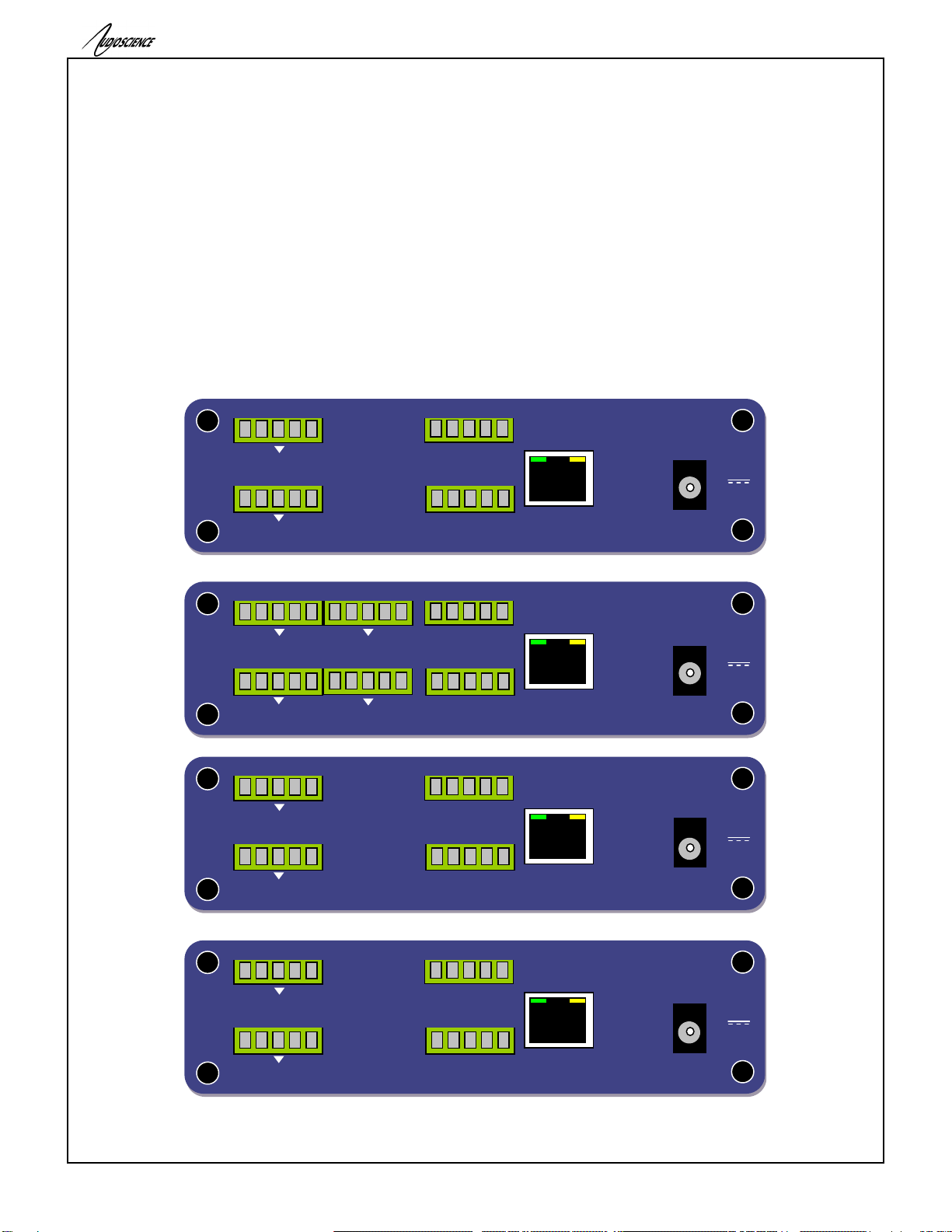
11.2 Back Panels
The following diagram shows the back panel of the 2.2M, 4.4M, 2.2D, 4.4D.
2.2M
4.4M
2.2D
4.4D
OUT 1 OUT 2
OUT 3 OUT 4
GPIO - RELAYS
5V DC
2A
AUDIOSCIENCE INC. , DELAWARE, USA - MADE IN USA - WWW.AUDIOSCIENCE.COM
PRIMARY
+ - + -
+ - + -
1 2 3 4 C
IN 1 IN 2
IN 3 IN 4
GPIO –OPTOS
+ - + -
+ - + -
1 2 3 4 V/G
10/100 ETHERNET
+ - + -
10/100 ETHERNET
1 2 3 4 V/G
1 2 3 4 C
+ - + -
PRIMARY
AUDIOSCIENCE INC. , DELAWARE, USA - MADE IN USA - WWW.AUDIOSCIENCE.COM
5V DC
2A
OUT 1 OUT 2
GPIO - RELAYS
GPIO –OPTOS
IN 1 IN 2
+ -
10/100 ETHERNET
1 2 3 4 V/G
1 2 3 4 C
+ -
PRIMARY
AUDIOSCIENCE INC. , DELAWARE, USA - MADE IN USA - WWW.AUDIOSCIENCE.COM
5V DC
2A
OUT 1
GPIO - RELAYS
GPIO –OPTOS
IN 1
AES/EBU
+ - + -
10/100 ETHERNET
1 2 3 4 V/G
1 2 3 4 C
+ - + -
PRIMARY
AUDIOSCIENCE INC. , DELAWARE, USA - MADE IN USA - WWW.AUDIOSCIENCE.COM
5V DC
2A
OUT 1 OUT 2
GPIO - RELAYS
GPIO –OPTOS
IN 1 IN 2
AES/EBU
Hono AVB 4.4M/4.4D/2.2M/2.2D
www.audioscience.com
11
14-Apr-15
11.2.1 OUT 1..4
2.2M & 4.4M:These are the balanced analog outputs. The middle pin of the 5pin terminal block is Ground
2.2D & 4.4D:These are the AES/EBU outputs. The middle pin of the 5pin terminal block is Ground
11.2.2 IN 1..4
2.2M & 4.4M:These are the balanced analog inputs. The middle pin of the 5pin terminal block is Ground.
2.2D & 4.4D:These are the AES/EBU inputs. The middle pin of the 5pin terminal block is Ground.
11.2.3 GPIO –RELAYS
These are the four GPIO Output relays
11.2.4 GPIO-OPTOS
These are four GPIO opto-isolated inputs. V/G is used to power the optos from either internal or external power.
11.2.5 RJ45 –PRIMARY+PoE
The primary network connection. Also provides PoE power input.
11.2.6 5V DC Jack
Provides input for an external +5V @ 2A power supply (supplied with the unit)
12 HARDWARE INSTALLATION
12.1 Mounting
12.1.1 Flange Mounting
The Hono Mini AVB interface mounts using the flanges on the side of the unit
12.1.2 Rack Mounting
The Hono Mini AVB interface can be rack mounted using the optional rackmount bracket (p/n ENC2305). This
bracket can mount up to two Hono Minis.
12.2 Ethernet Connection
A CAT-5 or better (CAT-5e, CAT-6 etc) network cable is required for 100baseT Ethernet operation. The cable
length between the Hono Mini interface and a network switch should not exceed 100 meters (328 feet)
OUT 1 OUT 2
OUT 3 OUT 4
GPIO - RELAYS
5V DC
2A
AUDIOSCIENCE INC. , DELAWARE, USA - MADE IN USA - WWW.AUDIOSCIENCE.COM
PRIMARY
+ - + -
+ - + -
1 2 3 4 C
IN 1 IN 2
IN 3 IN 4
GPIO –OPTOS
+ - + -
+ - + -
1 2 3 4 V/G
10/100 ETHERNET

Hono AVB 4.4M/4.4D/2.2M/2.2D
www.audioscience.com
12
14-Apr-15
12.2.1 PoE Power
If your network provides power-over-ethernet (PoE) capability, then you can use it to power the Hono Mini.
12.2.2 External +5V Power
The Hono Mini AVB interface can use external +5V power, supplied using a 2.5mm DC plug. This power takes
priority over the PoE power if both are supplied at the same time
13 OPERATION
13.1 Power up sequence
This section describes the power up sequence.
13.1.1 Power
Apply power to the unit by either using a PoE enabled network on the primary RJ45 jack or by plugging in the
external +5V power supply. You may apply both at the same time, but the external power supply will take priority.
13.1.2 Firmware images
The Hono Mini AVB interface boots from a firmware image stored in flash memory. There are two independent
firmware images stored in every unit. The two images are named “Factory” and “Update”. The “Factory” image is
a reference image that is in place should a “bad” image be downloaded to the device. The “Update” image is the
image that can be updated in the field if required.
13.1.3 Firmware loading sequence
When first powered up, each Hono Mini AVB interface performs the following sequence:
1. Checks for a valid “Update” firmware image.
2. Loads the Update image and starts running it.
3. Loads any control settings that may have been stored to flash.
In the case where the “Update” image is determined to be corrupt, the Factory image is loaded. This situation is
noted by the STATUS LED being lit as orange.
13.1.4 Loading the factory firmware image
The Hono Mini AVB interface can be forced to load the factory firmware image by depressing the CLEAR
SETTINGS button on front panel as power is applied to the device. Keep the button depressed while power is
applied. The STATUS LED will be lit as orange
14 CONFIGURATION
14.1 ASIControl Configuration
ASIControl is a Windows application that is installed along with the AudioScience drivers. If you are using an
AudioScience AVB adapter or an AudioScience non-AVB audio adapter in the PC, download and install the
combo driver, taking care to correctly select the 32bit or 64-bit version based on your operating system.
Run the driver .exe to install the driver components and be sure to select the second install option: “Standard PCI
+ Network Driver’.
After driver installation, ASIControl can be run from either the desktop icon or from Start All Programs
AudioScience ASIControl.
If there is more than one NIC in the PC, upon startup, ASIControl will first prompt the user for which network
interface to use to communicate with AVB devices.
To preserve control changes made to the Hono Mini AVB interface, ASIControl must be shut down. This will save
control settings to the unit’s flash memory, allowing the settings to be restored after a power cycle.
Hono AVB 4.4M/4.4D/2.2M/2.2D
www.audioscience.com
13
14-Apr-15
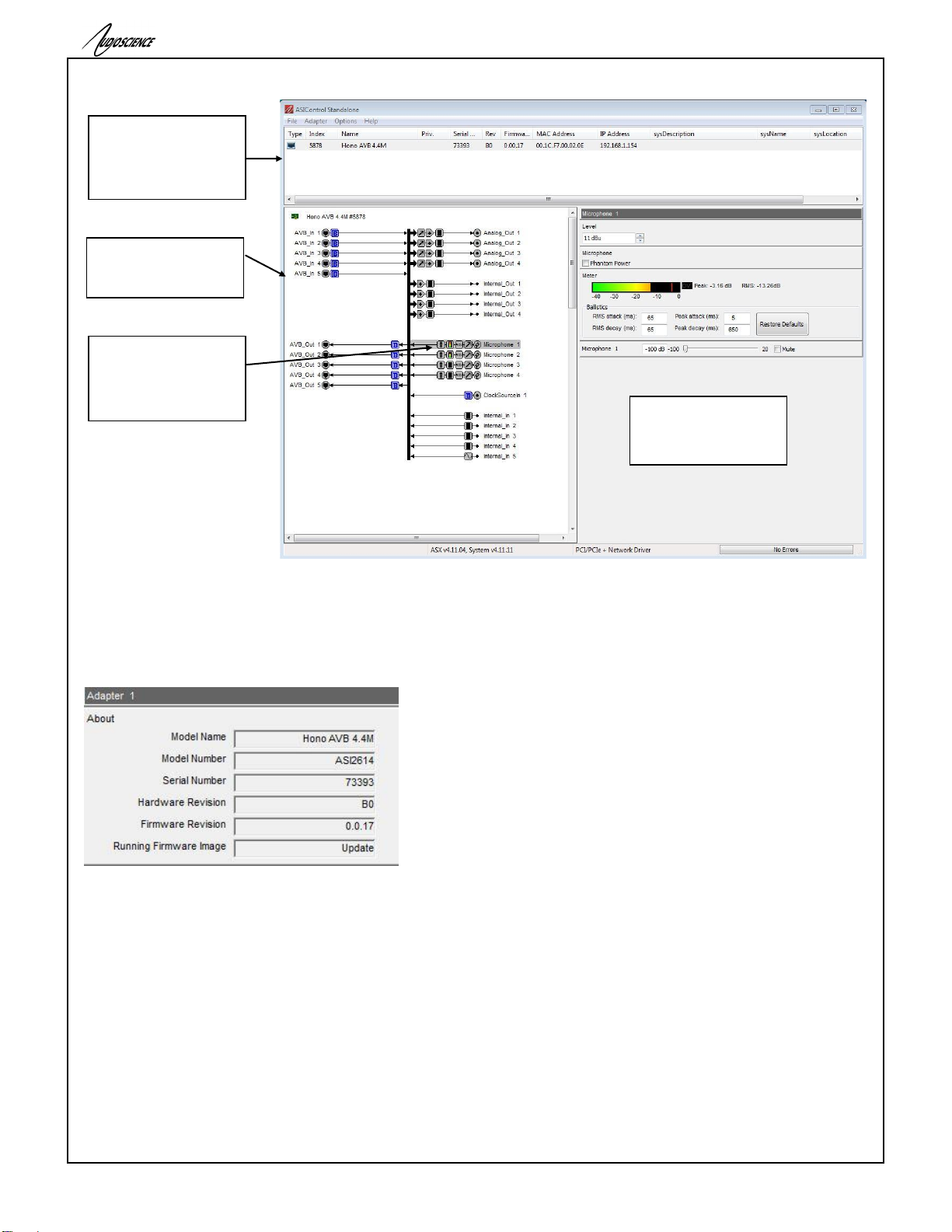
14.1.1 ASIControl Layout
Figure 1. ASIControl layout
14.1.2 About
This control displays information about the installed Hono AVB.
14.1.2.1 Interface
Figure 2. Adapter About information seen in right side of ASIControl.
Model Name:
The model name is displayed here.
Model Number:
The model number is displayed here.
Serial Number:
The serial number is displayed here.
Hardware Revision:
This lists the hardware revision.
Firmware Revision:
The firmware version is displayed; usually the same as the driver version installed.
List of AudioScience
AVB devices on the
network. Highlighted
device is shown in the
topology pane.
Topology pane showing
the inputs and outputs
of the selected adapter.
Node pane shows the
controls on the selected
node; in this case 1
Microphone 1.
The node 1 Microphone
1 has been selected by
left clicking with the
mouse. Its controls
show up in the node
pane.
Hono AVB 4.4M/4.4D/2.2M/2.2D
www.audioscience.com
14
14-Apr-15
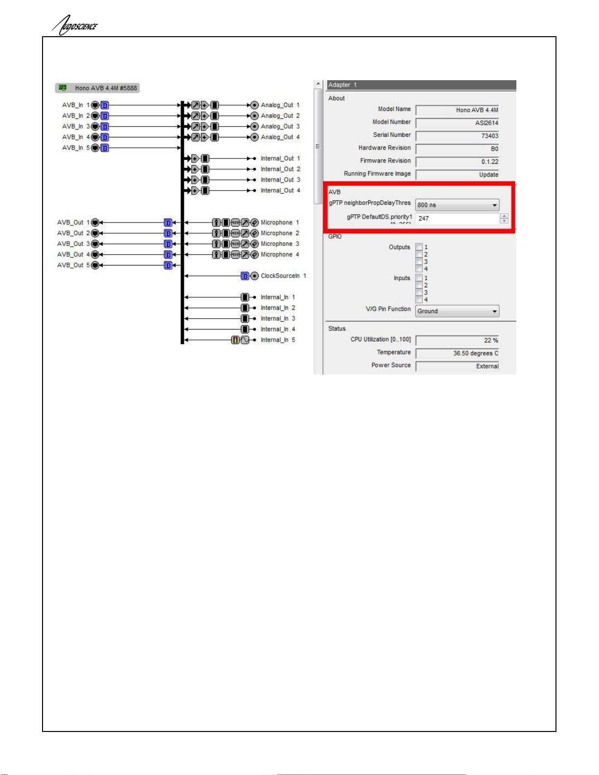
14.1.3 AVB
14.1.3.1 gPTP Configuration settings
neighborPropDelayThres:
The Hono AVB’s port’s AScapable flag is set to false when the measured pDelay to its neighbor exceeds a
specified threshold. The can be set to either 800ns (default) or 4 s. After changing the value the “Status” LED on
the front of the unit will flash while changes are saved. Do not reset the device while the “Status” LED is flashing
or your changes will not be stored.
DefaultDS.priority1:
You can also set the DefaultDS.priority1 in this section (value range 0-255), changes to this value will also cause
the “Status” LED to flash while changes are saved. Do not reset the device while the “Status” LED is flashing or
your changes will not be stored.

Hono AVB 4.4M/4.4D/2.2M/2.2D
www.audioscience.com
15
14-Apr-15
14.1.3.2 AVB_In
Clicking on any available “AVB_In”option will provide the following information as seen in the picture above.
*TS is an abbreviation for timestamp.
Packet Count
The number of 1722 packets received for this stream.
TS Uncertain Transition
The timestamp uncertain transition counter is incremented whenever timestamp uncertain field in the 1722 header
transitions from false to true. Typically this indicates that the talker loses its PTP timebase for some reason.
TS Valid Count
This counts the number of 1722 packets received with the timestamp valid bit set. Under normal operation every 3
in 4 1722 packets will have the timestamp valid bit set.
TS Invalid Count
This counts the number of 1722 packets received with the timestamp valid bit not set. Under normal operation
every 1 in 4 1722 packets will not have the timestamp valid bit set.
Seq Error Count
Every AVTP 1722 audio packet has a sequence number that increments every packet. The sequence error
records any instances where examination of the sequence number indicates that it did not increment by one.
Sample Error Count
The sample error count increment for every 1722 IEC 61883 sample decoded that does not have 0x40 in the
most significant byte.
Realign Count
When unpacking 1722 audio, the expectation is that the audio from every packet butts up exactly against the
audio of the previous sample. This means that there are no overlaps or holes in the audio sample sequence.
The realign count records the number of times that there was an overlap or gap during the packet unpack
process. In normal operation this counter should remain zero.

Hono AVB 4.4M/4.4D/2.2M/2.2D
www.audioscience.com
16
14-Apr-15
Max/Mean/StdDev TS to LR Edge Rounding
These fields measure the delta between the embedded 802.1AS presentation timestamp and the L/R edge of the
Hono Mini’s media clock. When the Hono is listening to an AVTP 1722 audio stream, every packet with a valid
timestamp is positioned in an output buffer according to its presentation time. The Hono “knows” the timestamps
of its own media clock in relation to its audio output buffer. The rounding field is a measure of how much rounding
occurs when determining which output “bin” to unpack the AVTP audio in to.
Under normal operation the StdDev should be less than 10ns. The expected mean depends on the
implementation of the talker. Some talkers deliberately make their PTP timestamp in the middle of the sample
time so that jitter is less likely to cause alignment to transition over a mediaclock edge. The most important thing
is to look for the mean offset to remain stable. If is it incrementing or decrementing it indicates that the talker and
listener mediaclocks are not locked.
14.1.4 Status
This control displays information on various dynamic parameters.
14.1.4.1 Interface
Figure 3. The Status user interface
CPU Utilization:
This shows the loading of the adapter’s CPU load in percent.
Temperature:
The internal temperature in degrees C is shown here.
Power Source:
PoE indicates the unit is running off Power-over-Ethernet. External indicates it is using the external +5V adapter.
14.1.5 Level
The levels in dBu for the adapter’s line_outs and line_ins can be adjusted here.
In the example below, the Line_Out 1 node in the topology view of ASIControl has been selected. Its Level will
show up on the right side of ASIControl. The same is done for a Line_In to see its Level.
Figure 4. Using ASIControl to select Analog_Out 1
14.1.5.1 Interface
Figure 5. Level displayed by ASIControl for Line_Out 1
Level:
The line out level can be adjusted by clicking the arrows or by typing values in to set the appropriate level.
Consult the specification section of this datasheet for the range of supported levels.
14.1.5.2 Developer
14.1.5.2.1 Windows APIs

Hono AVB 4.4M/4.4D/2.2M/2.2D
www.audioscience.com
17
14-Apr-15
Wave/Mixer –Analog levels are controlled using mixerSetControlDetails() on a control of type signed and with
the name Level/Trim.
HPI –Analog levels are controlled using the HPI_LevelSet() API.
ASX –Analog level are controlled using the ASX_Level_Set() API.
DirectSound –TBD.
14.1.5.2.2 Linux APIs
HPI –Analog levels are controlled using the HPI_LevelSet() API.
ASX –Analog level are controlled using the ASX_Level_Set() API.
ALSA –TBD.
14.1.6 Meter
Meters in ASIControl are located on audio nodes and display the audio level as the audio signal passes through
the node. Most AudioScience devices return both RMS and peak level readings and ASIControl displays both
simultaneously.
14.1.6.1 Interface
Figure 6. A stereo peak meter display; RMS is green and peak is yellow
To the right of the peak meter is the absolute readings in dBFS. These can be useful when testing input tones of a
specific known level.
14.1.6.2 Developer
14.1.6.2.1 Windows APIs
Wave/Mixer –Meters are read using mixerGetControlDetails() on a control of type signed and with type “Peak”
the name “Peak Meter”. A minimum value is 0 and maximum is 32767. The interface returns the peak readings
only, not the RSM level. It confirms to expected Windows functionality.
HPI –Meters are read using the HPI_Meterxxx() API.
ASX –Meters are read using the ASX_Meter_xxx() API.
DirectSound –TBD.
14.1.6.2.2 Linux APIs
HPI –Meters are read using the HPI_Meterxxx() API.
ASX –Meters are read using the ASX_Meter_xxx() API.
ALSA –TBD.
14.1.7 AES/EBU I/O
The Hono AVB 2.2D and 4.4D have AES/EBU I/O.
Hono AVB 2.2D –1 AES/EBU output and 1 AES/EBU input (2 channel I/O)
Hono AVB 4.4D –2 AES/EBU outputs and 2 AES/EBU inputs (4 channel I/O)
14.1.7.1 AES/EBU Inputs
Each AES/EBU input has a sample rate converter (SRC) on it and so may have a sample rate that is
asynchronous to the rest of the system. Valid sample rates are 32, 44.1, 48, 64, 88.2 and 96kHz.
14.1.7.2 AES/EBU Outputs
The AES/EBU outputs are clocked at 48kHz, the same rate as the AVB interface and cannot be changed.

Hono AVB 4.4M/4.4D/2.2M/2.2D
www.audioscience.com
18
14-Apr-15
14.1.8 Input and Output Volume Adjustment
All outputs from the Hono Mini AVB interface have volume adjustments in their path that support a range of –100
to + 20 dB. The nodes that support this are Analog_Out 1-4, Internal_out 1-4 and AES/EBU_Out 1-2.
Clicking on Analog_Out 1 in the topology pane of ASIControl will show a list of volumes in the node view pane. At
left is an image of the Level section, the first volume control and the Meter control shown in the node pane. The
meter is found after the full list of volumes (the Hono Mini AVB interface incorporates AudioScience’s anything to
anywhere’ mixing).
Figure 7. ASIControl node displays with volumes
The volumes are self-explanatory. Just drag the sliders. All lineouts also have an audio path (with volume) from
the corresponding line in. This can be use useful in verifying the correct operation of the audio modules without
having to send the audio across an AVB network.
14.1.9 Audio Delay –Future feature
The audio delay block supports user programmable delay per audio output. By default, each output has a
maximum of approximately 80 milliseconds of delay assigned to it. If a larger delay is required, more delay
storage can be assigned from the global unallocated pool of storage. The maximum delay is 10 seconds.
Figure 8 Using ASIControl to select Analog_Out 1
14.1.9.1 Interface
Figure 9 Audio Delay displayed in right pane
of ASIControl for Line_Out 1
Delay:
The audio delay is specified in MS (milliseconds), metres, and feet in the user interface. It can be adjusted by
typing in new values.
14.1.9.2 Developer
14.1.9.2.1 Windows APIs
HPI –The Audio Delay is a block control. See functions then Mixer, Blocks, Audio Delay.
ASX –TBD.
14.1.9.2.2 Linux APIs
HPI –The Audio Delay is a block control. See functions then Mixer, Blocks, Audio Delay.
ASX –TDB
ALSA –TBD.
14.1.10 Signal Generator
In the topology pane of ASIControl, click on Internal_In 5

Hono AVB 4.4M/4.4D/2.2M/2.2D
www.audioscience.com
19
14-Apr-15
Figure 10. Internal nodes as seen in ASIControl
to see the Signal Generator information in the node pane.
14.1.10.1Interface
Figure 11. Signal Generator User Interface as seen in ASIControl
Waveform:
The signal generator waveform type is fixed as a Sinewave.
Frequency:
The frequency is fixed at 750Hz.
Amplitude:
The amplitude is fixed at 0dBFS.
14.2 Mic/Line input configuration
For each mic/line input, the following can be configured
Phantom power
Input Level (Sensitivity)
Parametric Equalizer (future)
Compressor/Limiter (future)
Here are the controls as viewed in ASIControl’s node pane (its right pane):
Further information on each control follows.

Hono AVB 4.4M/4.4D/2.2M/2.2D
www.audioscience.com
20
14-Apr-15
14.2.1 Phantom Power
Phantom power (48v) can be set on/ off independently for each channel by checking/unchecking the checkbox.
Note: Phantom power cannot be turned on and will be disabled if the Level is higher than -9dBu.
14.2.2 Input Level
The input level can be set between –60 and +26dBu in 1dB increments by either using the up/down arrows to the
right of the Level textbox or by clicking in the Level textbox, typing in a particular number, and then hitting the
<Tab> key on the keyboard.
14.3 Access control using passwords –Future feature
Beginning with driver 4.10.00, some AudioScience adapters support password protected access to adapter
controls. In ASIControl, an adapter that supports passwords shows a padlock in its adapter information line of the
adapter list window. For example see
By default, if a password has not been set, the adapter operates as if there is no active password. Any user has
complete access to all the device functionality.
The access control system supports 3 different “user” login levels. They levels their associated privileges are
outlined in the following table.
Username
Controls
Scripting
Configuration
Save/restore
Passwords
Admin
Read/write
Read/write
Read/write
Write
User
Read
No access
No access
No access
Guest
Read
No access
No access
No access
Password information is stored on the adapter itself, not the host computer, so if a different computer is used to
control the adapter, the same passwords should be used.
14.3.1.1 Login in states
14.3.1.1.1 Admin
This is the default state if no passwords have been set on the device. Or, the user has logged in using the
Administrator password. This is indicated in the ASIControl as:
This manual suits for next models
3
Table of contents
Other AudioScience Recording Equipment manuals


