AudioScience lyo Dante 8.8M User manual

July 1, 2019
www.audioscience.com
1
July 1, 2019
DANTE®MICROPHONE/LINE INTERFACES
1 DESCRIPTION
The Iyo Dante® is a cost-effective family of microphone/line
Dante audio-over-IP (AoIP) interfaces in a 1U rack mount
format.
Several models provide various configurations of balanced
analog audio inputs and outputs. Each input accommodates
microphone through line level signals with a range of -60 to
+24dBu. +48V phantom power is individually switchable on
each input. Output levels are configurable up to +24dBu.
RGB LEDs on the Iyo’s front panel show per channel audio
levels and streaming status.
The Iyo family feature an embedded web server, allowing
configuration and monitoring of input and output levels.
Routing is achieved using the Dante Controller.
Power is provided from a built-in universal AC power supply.
Redundant power is available using an external 12VDC
supply via a locking 2.1mm jack.
All units can also be operated in AES67 interoperability mode.
2 FEATURES
From 8x8 to 32x32 channels of Dante® audio-over-IP
with AES67 interoperability
48 or 96kHz sample rates with 32bit A/D and D/A
conversion
Balanced microphone/line level inputs with level range of
-60 to +24dBu
Switchable +48V phantom power on each input
Balanced line level outputs with level range of 0 to
+24dBu.
3.81mm Terminal Block terminations, DB-25 or RJ-
45/StudioHub+GPIO.
RGB front panel LEDs provide per channel metering and
stream status
Built-in web server provides audio level configuration and
monitoring
Dual RJ-45 network jacks can be operated in redundant
or switched mode.
Built-in universal 90-260VAC 50/60Hz power supply.
Auxiliary +12VDC input provides power supply
redundancy.
3 MODEL INFORMATION
The following Iyo Dante models are available
Terminal block
DB-25
RJ-45 + GPIO
Model Name
Mic/Line
Inputs
Line
Outputs
Model Name
Mic/Line
Inputs
Line
Outputs
Model Name
Mic/Line
Inputs
Line
Outputs
Iyo Dante 8.8M
8
8
Iyo Dante 8.8MD
8
8
Iyo Dante 8.8MR
8
8
Iyo Dante 16.16M
16
16
Iyo Dante 16.16MD
16
16
Iyo Dante 16.16MR
16
16
Iyo Dante 32.32M
32
32
Iyo Dante 32.32MD
32
32
Iyo Dante 32.32MR
32
32
Iyo Dante 16.0M
16
0
Iyo Dante 16.0MD
16
0
Iyo Dante 16.0MR
16
0
Iyo Dante 32.0M
32
0
Iyo Dante 32.0MD
32
0
Iyo Dante 32.0MR
32
0
Iyo Dante 0.16L
0
16
Iyo Dante 0.16LD
0
16
Iyo Dante 0.16LR
0
16
Iyo Dante 0.32L
0
32
Iyo Dante 0.32LD
0
32
Iyo Dante 0.32LR
0
32

Iyo Dante
www.audioscience.com
2
July 1, 2019
4 SPECIFICATIONS
DANTE INPUT/OUTPUT
Type
100/1000Mb Ethernet
Connector
Dual RJ-45 operable as redundant Dante or as a network switch
Channels
8.8M –8 input and 8 output channels
16.16M –16 input and 16 output channels
32.32M –32 input and 32 output channels
16.0M –16 input and 0 output
0.16L –0 input and 16 output
32.0M –32 input and 0 output
0.32L –0 input and 32 output
Audio formats
16, 24 and 32 bits per sample
Sample Rate
48kHz, 96kHz
Latency
0.15, 0.25, 0.5, 1.0 and 5.0ms
ANALOG MIC/LINE INPUT
Type
Balanced
Input Level
-60 to +24dBu in 1dBu steps
EIN
-126 dBuEquivalent Input Noise @ -26dBu level setting
Phantom Power
+48V @ 10mA per channel max , software switchable
A/D converter
32 bit over sampling
Input Impedance
10K ohms
Dynamic Range [1]
>114dB
THD+N [2]
< -97dB
Frequency Response
@ 48kHz Sample Rate: 20Hz to 20kHz +0.1/-0.5dB
@ 96kHz Sample Rate: 20Hz to 40kHz +0.1/-2.0dB
Connectors
3.81mm Terminal Block, DB-25 or RJ-45/StudioHub+GPIO
ANALOG LINE OUTPUT
Type
Balanced
Output Level
-10 to +24dBu in 1dBu steps
D/A converter
32 bit over sampling
Load Impedance
2K ohms or greater
Dynamic Range [1]
>114dB
THD+N [2]
< -100dB
Frequency Response
@ 48kHz Sample Rate: 20Hz to 20kHz +0.1/-0.25dB
@ 96kHz Sample Rate: 20Hz to 40kHz +0.1/-3.0dB
Connectors
3.81mm Terminal Block, DB-25 or RJ-45/StudioHub+GPIO
LATENCY (48kHz)
Analog Input to Dante Transmit
TBD
Dante Receive to Analog Output
TBD
POWER
Built in Power supply
90-260VAC, 47-63Hz with IEC C-14 AC inlet
Redundant Power supply (Optional)
Supplied using an external +12VDC, 60W power supply with 2.1mm locking plug
REGULATORY
FCC Part 48 Class A (US)
CE Mark (EN55022 Class A EN55024)
RoHS Compliant
GENERAL
Dimensions
1 RU, 19”(482mm) W x 6”(152mm) L x 1.75”(44mm) H
Weight
5 lb (2.2kg) max (32.32M)
Operating Temperature
0C to 40C in free air
NOTES
[1] –Dynamic Range measured using a –60dB 1kHz sine wave +24dBu level and A weighting filter
[2] - THD+N measured using a -3 dbFs 1kHz sine wave, +20dBu level, sampled at 48kHz, 22-20kHz b/w and A weighting filter
[3] - Network latency is changeable using the Dante Controller

Iyo Dante
www.audioscience.com
3
July 1, 2019
5 REVISIONS
Date
Description
July 2018
1st Draft
Aug 2018
Added web interface and connectors section and initial About Dante
Sep 2018
Added front panel display section
Sep 2018
Added firmware download section
Oct 1 2018
Merged various drafts
Oct 2 2018
Updated screenshots of WebUI
Oct 11 2018
Added new model numbers
Feb 13 2019
Add Settings tab, update Meters and Inputs strip for Mute
June 12 2019
Updated block diagram to include mute icons
June 26 2019
Added DB-25 and RJ-45 connector options.

Iyo Dante
www.audioscience.com
4
July 1, 2019
6 CONTENTS
1DESCRIPTION............................................................................................................................................. 1
2FEATURES.................................................................................................................................................. 1
3MODEL INFORMATION............................................................................................................................... 1
4SPECIFICATIONS........................................................................................................................................ 2
5REVISIONS.................................................................................................................................................. 3
6CONTENTS.................................................................................................................................................. 4
7IMPORTANT SAFETY INSTRUCTIONS....................................................................................................... 5
8NOTICES ..................................................................................................................................................... 7
9ARCHITECTS & ENGINEERS SPECIFICATION.......................................................................................... 8
10 INTRODUCTION..................................................................................................................................... 8
ABOUT DANTE...........................................................................................................................................................810.1
11 HARDWARE INSTALLATION ................................................................................................................ 9
RACK MOUNTING ......................................................................................................................................................911.1 ETHERNET CONNECTION ...........................................................................................................................................911.2 AC POWER ................................................................................................................................................................911.3 REDUNDANT POWER SUPPLY ....................................................................................................................................911.4 HARDWARE LABEL....................................................................................................................................................911.5 AUDIO CONNECTIONS..............................................................................................................................................1011.6 3.81mm Terminal Block options 1011.6.1 DB-25 options 1111.6.2 RJ-45/StudioHub + GPIO options 1211.6.3
12 OPERATION......................................................................................................................................... 13
FRONT PANEL DISPLAY ...........................................................................................................................................1312.1 System info 1312.1.1 Meters 1312.1.2 Streaming 1312.1.3
13 BLOCK DIAGRAM ............................................................................................................................... 14
14 WEB INTERFACE ................................................................................................................................ 15
DEVICE TAB.............................................................................................................................................................1514.1 Device Information 1514.1.1 Software Information 1514.1.2 Device Status 1514.1.3
INPUT/TRANSMIT TAB..............................................................................................................................................1614.2 RECEIVE/OUTPUT TAB.............................................................................................................................................1714.3 SETTINGS TAB..........................................................................................................................................................1714.4
15 FIRMWARE UPDATES......................................................................................................................... 18

Iyo Dante
www.audioscience.com
5
July 1, 2019
7 IMPORTANT SAFETY INSTRUCTIONS
1. Read these instructions.
2. Keep these instructions.
3. Head all warnings.
4. Follow all instructions.
5. Do not use this apparatus near water.
6. Clean only with a dry cloth.
7. Do not block any ventilation openings. Install in accordance with the manufacturer’s instructions.
8. Do not install near any heat sources such as radiators, heat registers, stoves, or other apparatus
(including amplifiers) that produce heat.
9. Do not defeat the safety purpose of the polarized or grounding-type plug. A polarized plug has two
blades with one wider than the other. A grounding type plug has two blades and a third grounding prong.
The wide blade or the third prong is provided for your safety. If the provided plug does not fit into your
outlet, consult an electrician for replacement of the obsolete outlet.
10. Protect the power cord from being walked on or pinched, particularly at plug ends, convenience
receptacles, and the point where they exit from the apparatus.
11. Only use attachments/accessories specified by the manufacturer.
12. Use only with the cart, stand, tripod, bracket, or table specified by the manufacturer, or sold with the
apparatus. When a cart is used, use caution when moving the cart/apparatus combination to avoid injury
from tip-over.
13. Unplug this apparatus during lightning storms or when unused for long periods of time.
14. Refer all servicing to qualified service personal. Servicing is required when the apparatus has been
damaged in any way, such as power-supply cord or plug is damaged, liquid has been spilled or objects
have fallen into the apparatus, the apparatus has been exposed to rain or moisture, does not operate
normally, or has been dropped.

Iyo Dante
www.audioscience.com
6
July 1, 2019
This symbol is intended to alert the user to the presence of uninsulated dangerous voltage within
the product’s enclosure that may be of sufficient magnitude to constitute a risk of electric shock to
humans
This symbol is intended to alert the users to the presence of important operating and maintenance
(servicing) instructions in the literature accompanying the product.
CAUTION: To reduce the risk of electric shock, do not remove the cover. No user-serviceable parts inside.
WARNING:
1. To prevent fire or electric shock, do not expose this apparatus to rain or moisture.
2. This apparatus shall not be exposed to dripping or splashing and no objects filled with liquids, such
as a vase, shall be placed on the apparatus.
3. This is a Class 1 apparatus, and as such must be connected to a mains socket outlet with a
protective earthing connection.
4. The mains plug is used as the disconnect device and shall remain readily operable.
CAUTION
RISK OF ELECTRICAL SHOCK
DO NOT OPEN

Iyo Dante
www.audioscience.com
7
July 1, 2019
8 NOTICES
FEDERAL COMMUNICATIONS COMMISSION (FCC) INFORMATION
NOTE: This equipment has been tested and found to comply with the limits for a Class A digital device,
pursuant to Part 15 of the FCC Rules. These limits are designed to provide reasonable protection against
harmful interference in a commercial installation. This equipment generates, uses, and can radiate radio
frequency energy and, if not installed and used in accordance with the instructions, may cause harmful
interference to radio communications. Operation of this equipment in a residential area is likely to cause
harmful interference, in which case the user will be required to correct the interference at his or her own
expense.

Iyo Dante
www.audioscience.com
8
July 1, 2019
9 ARCHITECTS & ENGINEERS SPECIFICATION
10INTRODUCTION
About Dante10.1
Based on industry standards, Audinate created Dante, an uncompressed, multi-channel digital media networking
technology, with near-zero latency and synchronization. Dante is the preferred audio networking solution that has
been adopted by more pro-audio AV manufacturers than any other networking technology. Interoperability is not a
dream of the future, but a reality today. Hundreds of Dante-enabled products are available from the world’s
leading manufacturers, enabling you to mix devices from multiple manufacturers.
One cable does it all. Dante does away with heavy, expensive analog or multicore cabling, replacing it with low-
cost, easily-available CAT5e, CAT6, or fiber optic cable for a simple, lightweight, and economical solution. Dante
integrates media and control for your entire system over a single, standard IP network.
Dante systems can easily scale from a simple pairing of a console to a computer, to large capacity networks
running thousands of audio channels. Because Dante uses logical routes instead of physical point-to-point
connections, the network can be expanded and reconfigured at any time with just a few mouse clicks.
Iyo Dante
www.audioscience.com
9
July 1, 2019
11 HARDWARE INSTALLATION
Rack Mounting11.1
The Iyo is 1 RU (1 rack unit/space) high and mounts in a standard 19-inch equipment rack.
Use four mounting screws to fasten the front panel of the Iyo to the 19-inch rack rails.
Support any cables that are attached to the back of the Iyo so that their weight does not put undue stress
on the unit’s connectors.
The Iyo has cooling vents on the side of the unit. Be careful not to obstruct these.
Ethernet Connection11.2
There are 2 RJ-45 Ethernet jacks on the rear of the Iyo, a Primary and a Secondary. A CAT-6 or better network
cable is required for 1000baseT Ethernet operation. For initial setup, connect your Dante network to the Primary
Ethernet jack. See Section on Ethernet connections for information on utilizing the Secondary jack. The cable
length between the Iyo and a network switch should not exceed 100 meters (328 feet)
AC Power11.3
The detachable AC power cord that comes with the Iyo plugs into the IEC connector on the chassis.
The Iyo operates with AC voltages from 90 to 260VAC, 47 to 63Hz. No selection of voltage or frequency is
required, the Iyo’s power supply will automatically adjust.
Use only an AC power source with a protective earth ground.
The Iyo has no power switch. Detach the AC power cord to remove power
Redundant Power Supply11.4
The Iyo can optionally be connected to a second power supply to offer redundancy. The +12VDC power supply
(AudioScience p/n PWR1101) is connected to the Iyo using a locking 2.1mm plug.
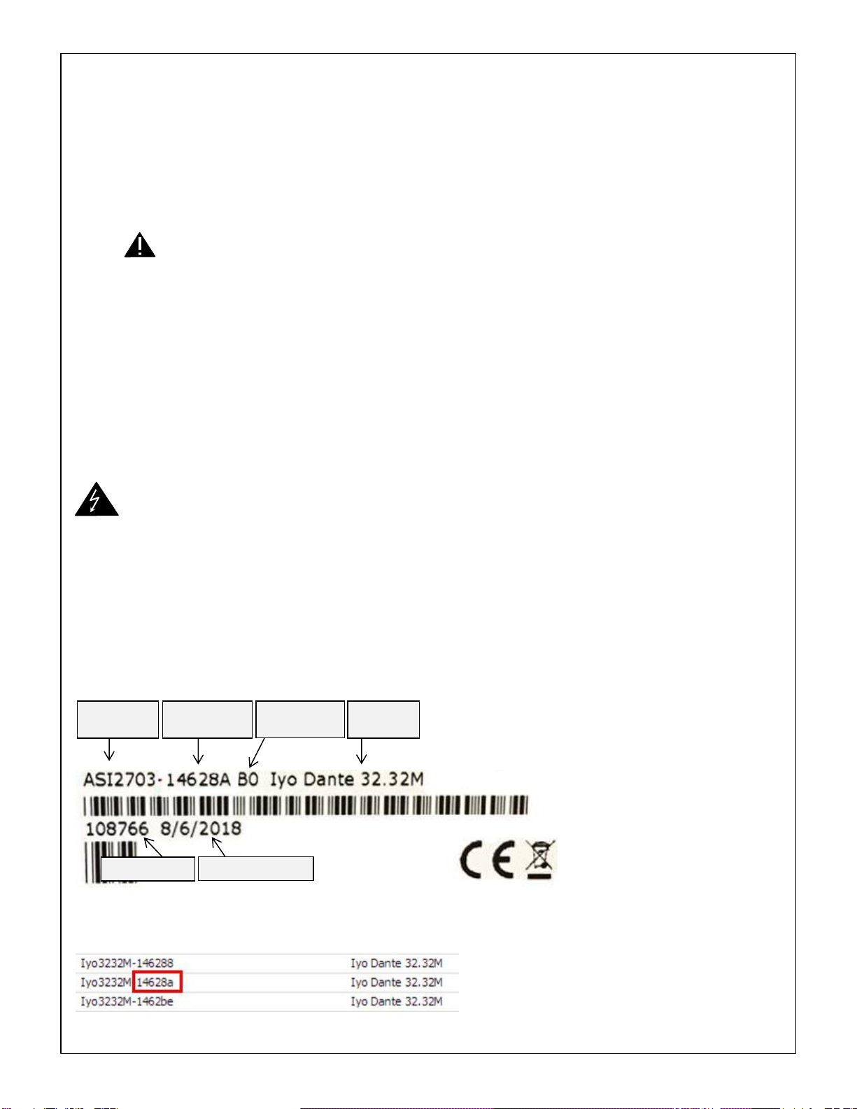
Hardware Label11.5
All AudioScience products are shipped with a label showing various hardware specifications. This information can
be helpful in configuring your unit and you will need it if you ever need to return your unit for service.
*MAC address information can be used to help identify your unit in Dante Controller. It will be displayed in the
Device Name field along with the model name.
Model
number
MAC address
last 6 digits*
Model
name
Manufacture date
Hardware
revision
Serial number
Iyo Dante
www.audioscience.com
10
July 1, 2019
Audio Connections11.6
The Iyo Dante family of interfaces use either 3.81mm Terminal Block terminations, DB-25 connectors or RJ-
45/StudioHub+GPIO connectors to make audio connections to your input and output devices.
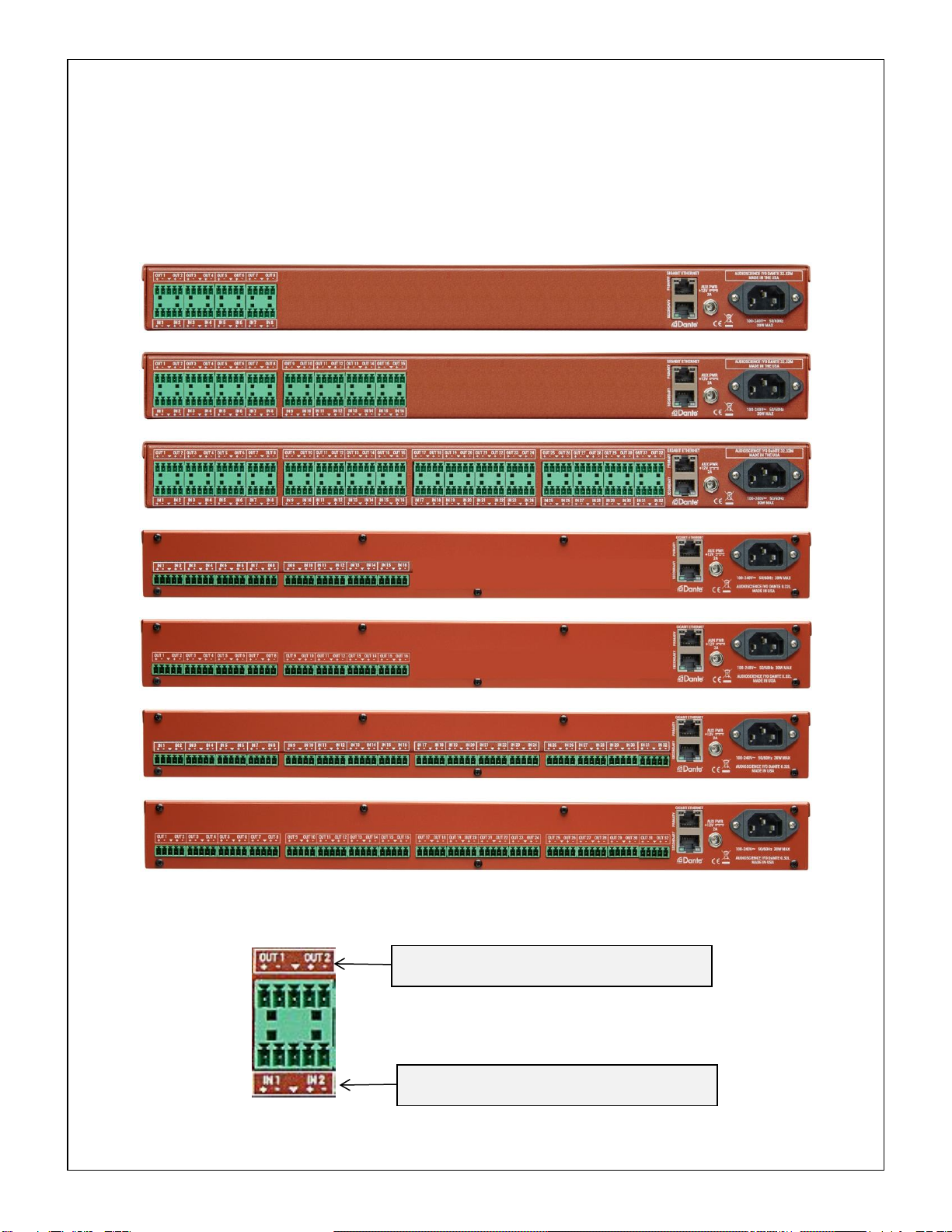
3.81mm Terminal Block options11.6.1
When viewed from the back, output jacks are located in the top row, starting with Out 1 at the far left. Input jacks
are located in the bottom row and also start at Input 1 on the far left.
Iyo Dante 8.8M
Iyo Dante 16.16M
Iyo Dante 32.32M
Iyo Dante 16.0M
Iyo Dante 0.16L
Iyo Dante 32.0M
Iyo Dante 0.32L
Terminal Block Connector close-up11.6.1.1
Each individual 3.81mm Terminal Block accommodates 2 audio channels with a shared ground.
Output wiring
Out 1+ | Out 1- | Ground | Out 2 + | Out 2 -
Input wiring
In 1+ | In 1- | Ground | In 2 + | In 2 -

Iyo Dante
www.audioscience.com
11
July 1, 2019
DB-25 options11.6.2
Iyo Dante 8.8MD
Iyo Dante 16.16MD
Iyo Dante 32.32MD
Iyo Dante 16.0MD
Iyo Dante 0.16LD
Iyo Dante 32.0MD
Iyo Dante 0.32LD
DB-25 Connector close-up11.6.2.1
The DB-25 pinouts correspond to the AES59-2012 standard.
Iyo Dante
www.audioscience.com
12
July 1, 2019
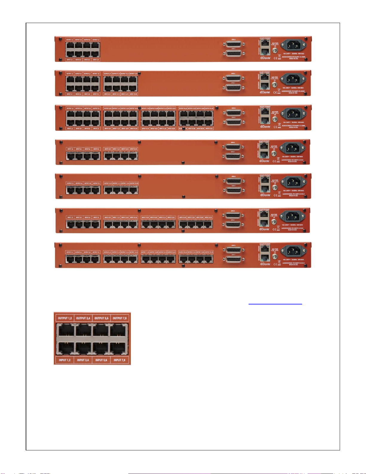
RJ-45/StudioHub + GPIO options11.6.3
Iyo Dante 8.8MR
Iyo Dante 16.16MR
Iyo Dante 32.32MR
Iyo Dante 16.0MR
Iyo Dante 0.16LR
Iyo Dante 32.0MR
Iyo Dante 0.32LR
RJ-45/StudioHub + GPIO Connector close-up11.6.3.1
The RJ45 pinouts follow the StudioHub format. More information can be found at www.studiohub.com
Iyo Dante
www.audioscience.com
13
July 1, 2019
12 OPERATION
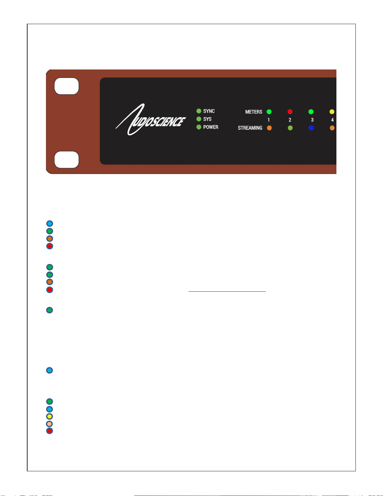
Front Panel Display12.1
The front panel LED display shows status and meter readings from the Iyo Dante
System info12.1.1
The system info section consists of 3 LED indicators, SYNC, SYS and POWER. This section gives you an at-a-
glance indication of the status of a few key parameters
SYNC: Displays the status of the IEEE1588 Precision Time Protocol (PTP) condition of the unit.
Blue indicates this unit is the elected PTP Master Clock.
Green indicates the Iyo is a PTP Slave.
Orange indicates the Iyo is in the process of synchronizing.
Red indicates there is a PTP error.
SYS: Displays the system operating status.
Green indicates the Iyo is functioning normally
Flashing Green indicates the configuration is being saved
Orange means the Iyo is in a transient waiting state, e.g. pending reboot.
Red indicates a critical hardware error. Contact support@audioscience.com for help.
POWER: Displays power status
Green indicates the Iyo is powered on
Off indicates no power to unit
Meters12.1.2
The meter section gives you a quick indicator of the current audio levels being passed through the unit on a color
scale from green (low signal) to bright red (indicating clipping or very high level). The color scale follows the same
intervals as the color scale shown in the web interface section below.
Blue (flashing): Input channel is muted
Streaming12.1.3
The streaming section displays status for each channel Dante interface.
Green: Input/Output –Streaming Dante –unicast
Blue: Input/Output –Streaming Dante and/or AES67 –multicast
Yellow: Output only –Streaming Dante –Loop back to receiver (shown on Receive LED only)
Orange: Output only –Setting up flow
Red: Output only –Stream error –RX status is not one of the following:
NONE | LOOPBACK | IN_PROGRESS | DYNAMIC | STATIC | MANUAL
Iyo Dante
www.audioscience.com
14
July 1, 2019
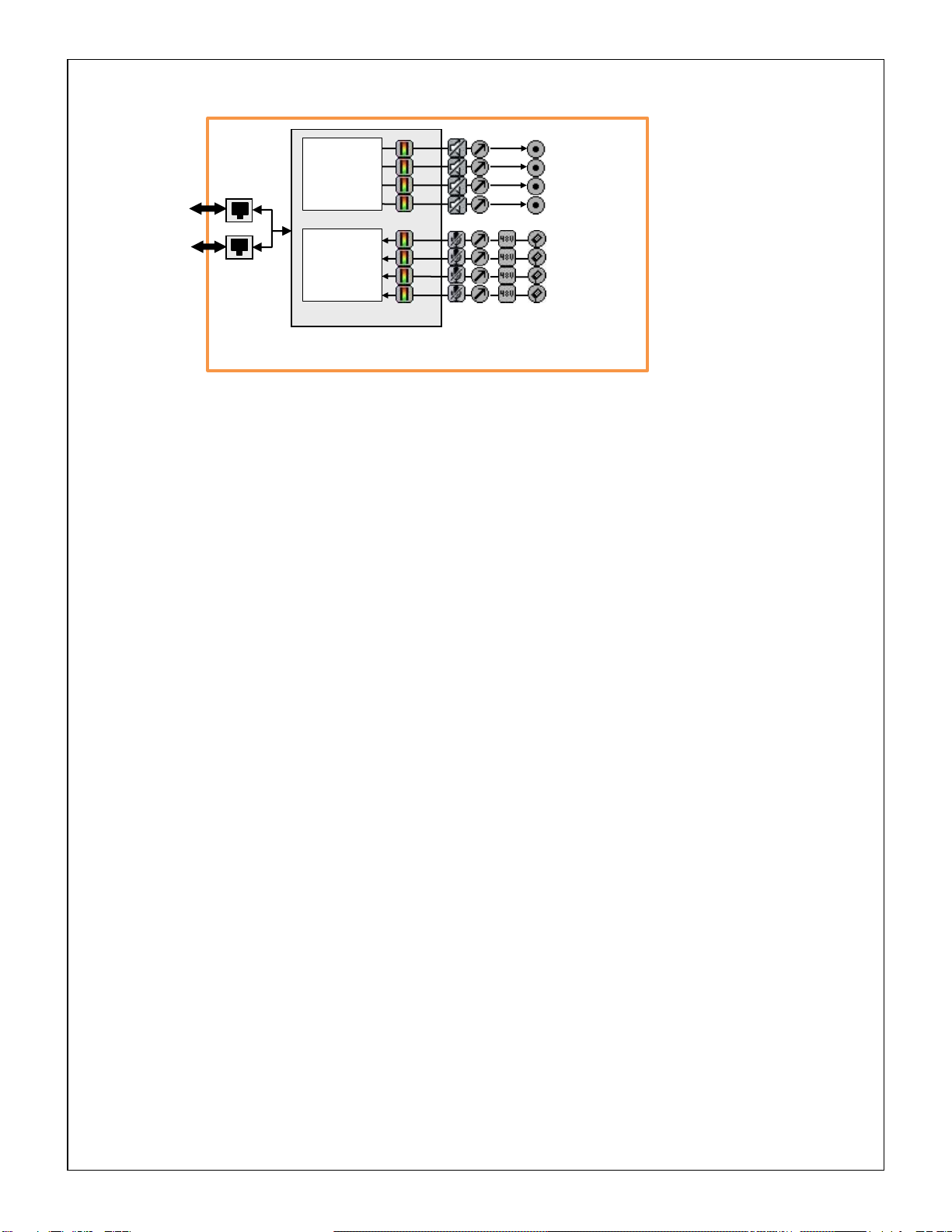
13BLOCK DIAGRAM
AudioScience Iyo Dante Mic/Line Interfaces
Dante Brooklyn II
1Gb
Ethernet
RJ-45
Primary
Line Out 3
Line Out 2
Line Out 1
Line Out 32*
Mic/Line In 2
Mic/Line In 3
Mic/Line In 32*
Mic/Line In 1
1Gb
Ethernet
(Secondary)
RJ-45
Secondary
Dante
AES67
Audio Out
Dante
AES67
Audio In
*Total inputs/outputs varies
based on model: 8, 16 or 32

Iyo Dante
www.audioscience.com
15
July 1, 2019
14WEB INTERFACE
The Iyo family feature an embedded web server, allowing configuration and monitoring of input and output levels.
To access the web interface, open your browser and type in your device’s IP address.
To find your unit’s IP address open Dante Controller and go to the Device Info tab. The IP address will be shown
in the Primary Address field as seen below
You will be presented with the following screen:
Select from the available tabs across the top, they are Device –Input/Transmit –Receive/Output. The Device tab
as shown above is selected by default when you first open the web interface.
Device tab
14.1
Device Information14.1.1
The Device Information section details the specific hardware information.
Model Name: The exact model type you are accessing
Model Number: Model number of this device
Hardware Revision: Hardware version of this device
Serial Number: Specific serial number for this device
Primary MAC Address: This unit’s Media Access Control Address
Firmware: Currently loaded AudioScience firmware version
Software Information14.1.2
The Software Information section details the specifics of the software and firmware installed.
AudioScience: Version of AudioScience firmware installed
XMOS: Version of code running on the embedded XMOS device
Device Status14.1.3
The Device Status section gives you an at-a-glance indication of the status of a few key parameters
Sync: Displays the status of the IEEE1588 Precision Time Protocol (PTP) condition of the unit.
Blue indicates this unit is the elected PTP Master Clock.
Green indicates the Iyo is a PTP Slave.
Orange indicates the Iyo is in the process of synchronizing.
Red indicates there is a PTP error.

Iyo Dante
www.audioscience.com
16
July 1, 2019
Sys: Displays the system operating status.
Green indicates the Iyo is functioning normally
Orange means the Iyo is in a transient waiting state, e.g. pending reboot.
Red indicates a hardware error. Hoover the mouse over the LED to read more error details.
Identify: This will cause all of the LEDs on the front panel to flash to help you identify a particular hardware unit.
Input/Transmit tab14.2
The Input/Transmit tab shows a channel strip for each microphone/line input. Each input becomes a Dante
transmit channel that is available for routing in the Dante Controller. The channel strip has a peak meter, input
level control and a toggle button to enable 48V phantom power. Gain must be set higher than 24dB in order to
use phantom power.
Channel name
Current level in dBFS.
Shows red Clip when levels
reach 0dbBFs
Input meters
From -1 to -60 dbFS
Gain control. Click blue dot and move mouse to change. Or
double-click on the number to enter a value directly. Both gain
and equivalent maximum level are displayed. 24dbu level
corresponds to 0dB Gain.
Phantom power toggle. Red when active
Phantom power is not applicable for gain 0dB to 24dB
Inputs can be muted by clicking here.
Muted inputs will show a blue button
Iyo Dante
www.audioscience.com
17
July 1, 2019
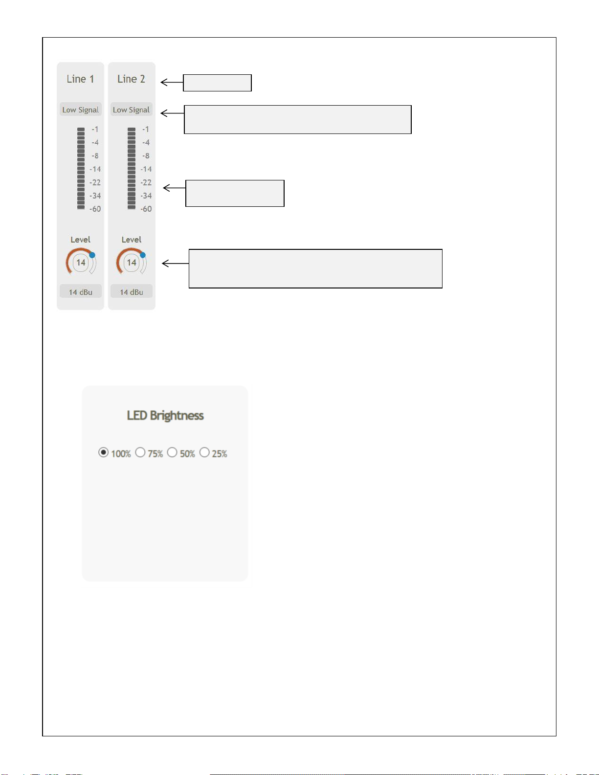
Receive/Output tab14.3
The Receive/Output tab show audio levels for signals being received from other Dante units on the network that
are then routed to the physical outputs of the Iyo.
Settings tab14.4
The settings tab can be used to control the brightness of the front panel LEDs
Level control. Click blue dot and move mouse to change. Or double-
click on number to enter a value directly. Level sets the output signal
amplitude (in dBu) that corresponds to a 0dBFs internal signal.
Channel name
Current level in dBFS. Shows red Clip when levels reach
0dBFs and “low Signal” when there is nothing being received
Output meters.
From -1 to -60 dbFS
Iyo Dante
www.audioscience.com
18
July 1, 2019
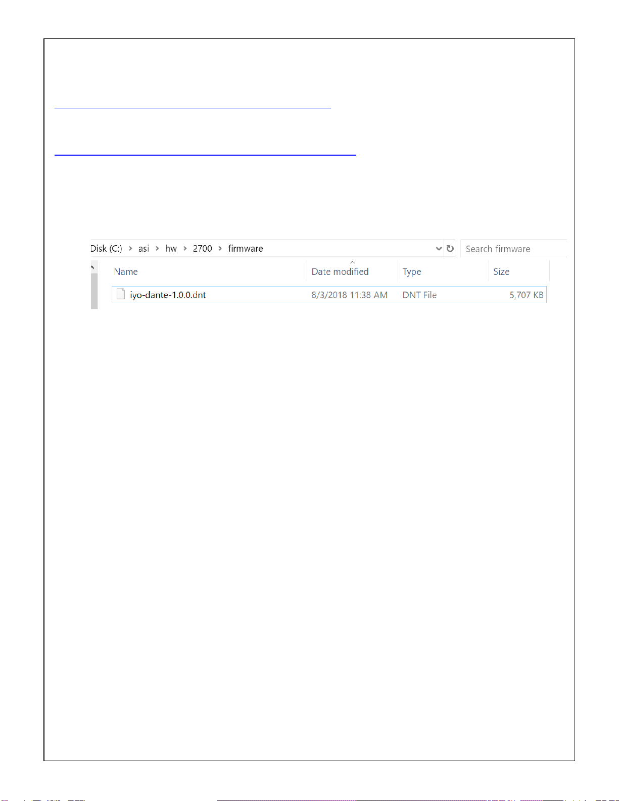
15FIRMWARE UPDATES
The Iyo Dante device firmware is updated using the Dante Firmware Update Manager. This can be found here:
https://www.audinate.com/products/firmware-update-manager
The latest firmware file for the Iyo Dante can be found on AudioScience’s website here:
http://www.audioscience.com/internet/download/firmware/iyo/dante/
There is one version of the firmware that runs on all Iyo Dante units.
To load new firmware onto the Iyo Dante:
1. Download the version of the Iyo Dante firmware you wish to install to a local directory
2. Run the Dante Firmware Manager
3. Select the Ethernet interface to use
4. Select “Update Dante Firmware”
5. Browse for the file you downloaded in step 1
6. Wait while the Update Manager searches for Iyo Dante devices on the network
7. Select the device that you wish to upload the firmware to
8. Start the upload process, it will take several minutes
9. When the firmware update is complete, the device will automatically reboot with the new version
[end]
This manual suits for next models
13
Table of contents
Other AudioScience Recording Equipment manuals


Popular Recording Equipment manuals by other brands

ALRIGHT DEVICES
ALRIGHT DEVICES Chronoblob2 user manual

Better Music Builder
Better Music Builder DX-3000 G2 owner's manual

Behringer
Behringer ULTRA-DI DI100 user manual

GEERFAB AUDIO
GEERFAB AUDIO D.BOB user manual

Blackstar Amplification
Blackstar Amplification Carry-on FOLDING CONTROLLER 25 owner's manual

Noise Engineering
Noise Engineering Loquelic Iteritas manual


