manuals.online logo
Brands
  1. Home
  2. •
  3. Brands
  4. •
  5. Audix
  6. •
  7. Microphone
  8. •
  9. Audix M63 Troubleshooting guide

Audix M63 Troubleshooting guide

M63
INSTALLATION &
OPERATING GUIDE
1. Mark placement using the provided M63 template.
2. Remove (2) screws from LED plate; remove plate. (figure 1)
3. Remove grill (figure 2)
4. For wood screw mounting evaluate surface depth and select appropriate screw
length (2 ea as provided) [ 1 ¼” #6 ]
5. For machine screw mounting evaluate surface depth and select appropriate screw
length (2 ea as provided) [ 2” 6/32 machined screw with nut and washer ]
6. Refasten grill and LED plate
The M63 is a condenser boundary microphone that features external DSP logic
control, as well as an internal microprocessor logic that provides common DSP
functions in local mode with programmable toggle on/o, momentary talk or mute
switching and (red/green) LEDs indicating active/mute status.
The M63 uses Micros™ series technology oering superior audio performance
optimized for speech and the industry’s first patented internal suspension system
reducing vibration noise.
For installations that do not require elaborate DSP programming, the M63 provides an
easy-to-operate solution without the cost and labor required for DSP operation when
set to internal logic mode.
IN THE BOX
• M63 microphone
• Spec sheet
• Installation guide
• Template
PERMANENT MOUNTING INSTALLATION
OVERVIEW
FIGURE 1 FIGURE 2
POWERING UP THE M63
When phantom power (48V) is supplied to the M63, the LEDs will blink red and green
to indicate that the unit is receiving power. Following the power-up sequence, the
LEDs will behave according to the setting specified by the DIP switch configuration.
*When connecting to a DSP, DIP switch 3 is always set to the left position.
SWITCH USE SETTING
SW1 Determines whether LEDs will be used to
indicate both active and muted states
RIGHT: Active and mute status with alternate color LEDs
LEFT: Only active state will be indicated by LEDs
SW2 Determines whether red or green
LED indicates active state
RIGHT: Active is green
LEFT: Active is red
SW3* Sets microphone to local (internal logic)
mode or external DSP logic control
RIGHT: Local control
LEFT: External DSP logic
SW4 Sets microphone’s initial state to ON or MUTE
when phantom power is supplied (SW4 is
disabled when SW3 is in external DSP)
RIGHT: Press to activate (muted on power-up)
LEFT: Press to mute (active on power-up)
SW5 Determines whether mic is in
toggle or momentary mode
RIGHT: Toggle between active and mute status
LEFT: Momentary. Press and hold button to maintain
either active or muted state (as specified by SW4)
SW6 Not assigned
SW1 LEFT: LEDs for active only SW1 RIGHT: LEDs for active and muted
SW2 LEFT: Active LED color red SW2 RIGHT: Active LED color green
SW3 LEFT: External DSP logic SW3 RIGHT: Internal local logic
SW4 LEFT: Mic on at power up SW4 RIGHT: Mic o at power up
SW5 LEFT: Mic switch momentary SW5 RIGHT: Mic switch toggle
SW6 LEFT:Not assigned SW6 RIGHT:Not assigned
DIP SWITCH SETTINGS
DIP switches can be accessed by
removing the grille (see Mounting for
removal instructions). To locate the DIP
switches, refer to the illustration at right.
DIP SWITCHES
SW 6
PUSH
L R
M63D v1.0
© 2019 Audix Corporation. Audix is a registered trademark of the Audix
corporation. Specifications subject to change without notice. For service
and warranty information, visit AudixUSA.com/service or call 800.966.8261
PIN / WIRE ASSIGNMENTS
The M63 is shipped with two 3-pin terminal blocks. One terminal block is for Audio
connection (audio A+, A-, Ground) and it is the only connection required for audio
and internal logic functionality as described in the overview. The second terminal
block (LED, C.C. Ground) is for use when connected to a DSP for control of LEDs and
contact closure. Two mating pair terminal block connectors are included in the box
for field connection, if needed.
CONNECTING TO A DSP
IMPORTANT:When connecting to a DSP, DIP switch 3 is always set to the left position.
GREEN Logic Input (LED Control)
WHITE Logic Output (Button)
BLUE Logic GND
DSP AUDIO
INPUT PORT
DSP LOGIC
I/O PORT
AUDIX M63’S
PHOENIX CONNECTOR
AUDIX M63’S
PHOENIX CONNECTOR
TO M63
TO M63
RED Audio (+)
BLACK Audio (–)
SHIELD GND/case
GREEN
GROUND
GROUND
GROUND
WHITE
BLACK
AUDIO (–)
BLUE
RED
AUDIO (+)
LED LOGIC IN
GROUND
CONTACT CLOSURE
AUDIO (–)
GROUND
AUDIO (+)

Other Audix Microphone manuals

Audix M40 User manual

Audix

Audix M40 User manual

Audix Micros M1280 Installation guide

Audix

Audix Micros M1280 Installation guide
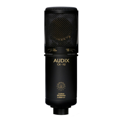
Audix CX-112 User manual

Audix

Audix CX-112 User manual

Audix OM2 Installation guide

Audix

Audix OM2 Installation guide

Audix USB12 User manual

Audix

Audix USB12 User manual

Audix OM6 User manual

Audix

Audix OM6 User manual
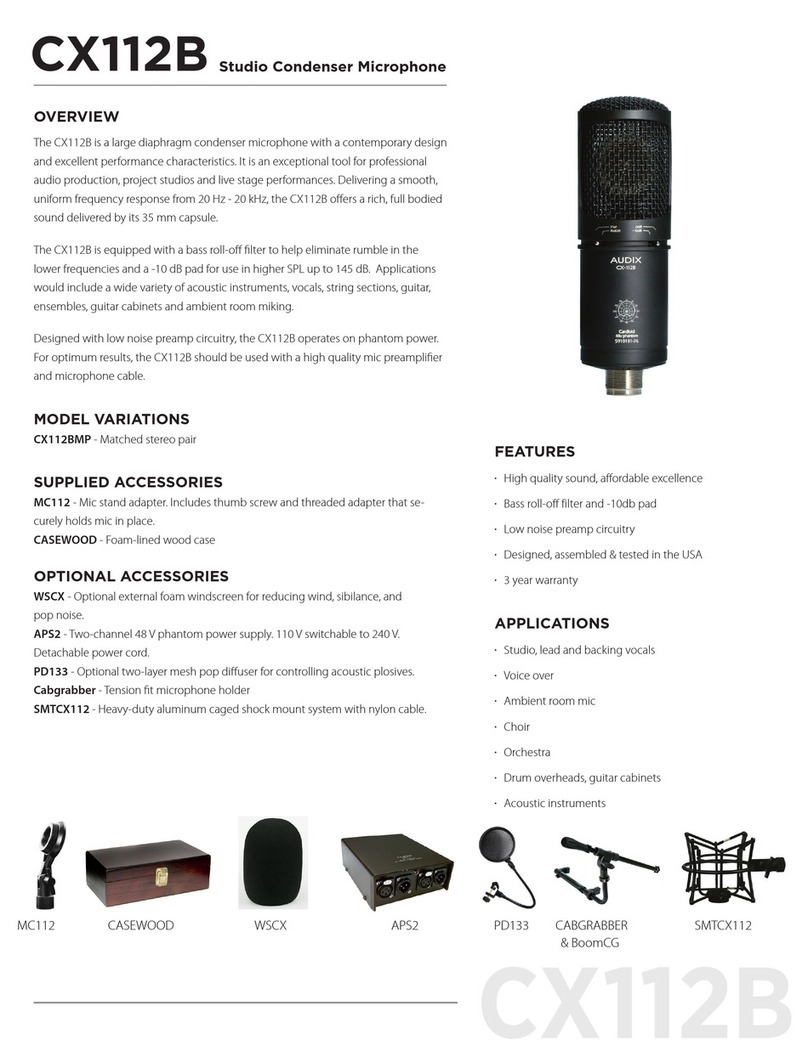
Audix CX112B User manual

Audix

Audix CX112B User manual
Audix M70WD Troubleshooting guide

Audix

Audix M70WD Troubleshooting guide
Audix MGN Series User manual

Audix

Audix MGN Series User manual

Audix Fisuon Series User manual

Audix

Audix Fisuon Series User manual
Audix M70-W User manual

Audix

Audix M70-W User manual
Audix D6 Installation and operation manual

Audix

Audix D6 Installation and operation manual

Audix L5 User manual

Audix

Audix L5 User manual

Audix M40 User manual

Audix

Audix M40 User manual
Audix ADX20i User manual

Audix

Audix ADX20i User manual
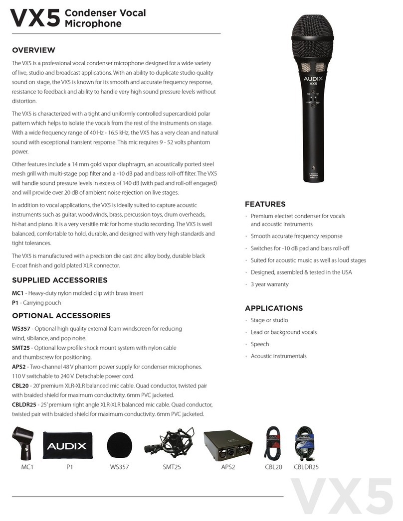
Audix VX5 User manual

Audix

Audix VX5 User manual

Audix M70WD Troubleshooting guide

Audix

Audix M70WD Troubleshooting guide
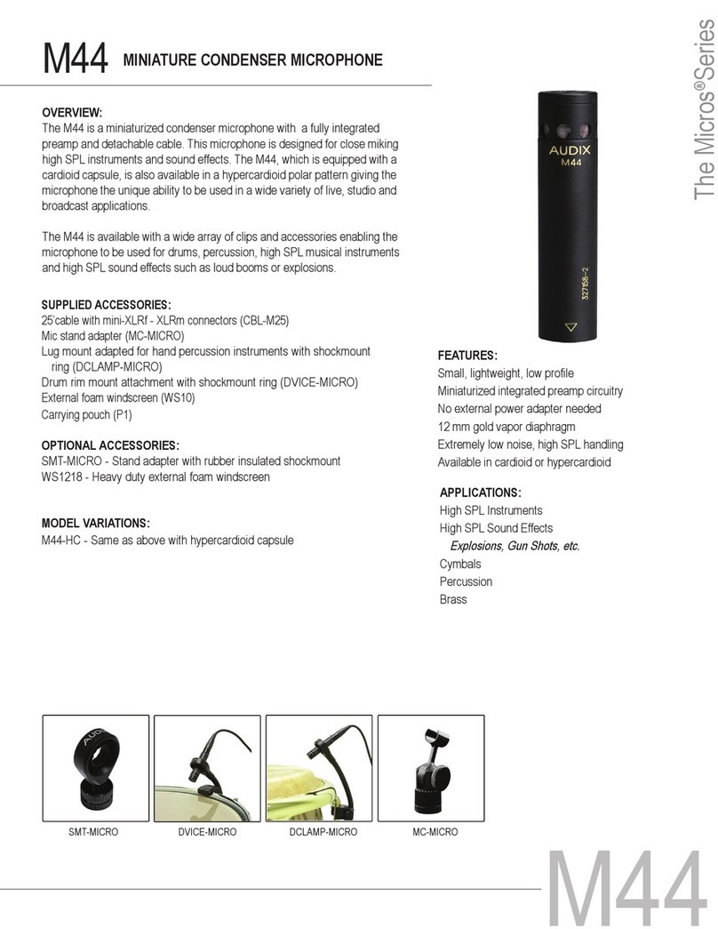
Audix M44 User manual

Audix

Audix M44 User manual

Audix M1250B User manual

Audix

Audix M1250B User manual
Audix M3-W User manual

Audix

Audix M3-W User manual

Audix HT2 User manual

Audix

Audix HT2 User manual

Audix M70 User manual

Audix

Audix M70 User manual

Audix M55WD Troubleshooting guide

Audix

Audix M55WD Troubleshooting guide

Audix M55 User manual

Audix

Audix M55 User manual

Popular Microphone manuals by other brands
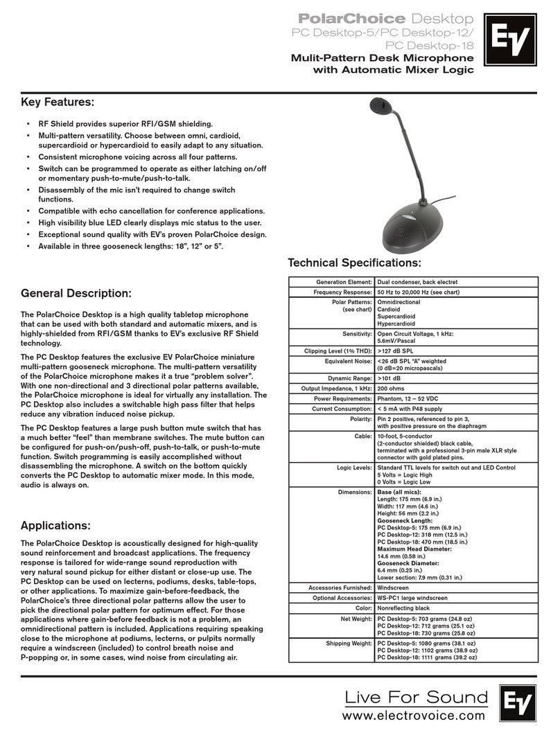
Electro-Voice PolarChoice Desktop Series quick start guide
Electro-Voice

Electro-Voice PolarChoice Desktop Series quick start guide

Nady Systems Center Stage Dynamic Microphone manual 
Nady Systems

Nady Systems Center Stage Dynamic Microphone manual 

The Singing Machine CPK565 user manual
The Singing Machine

The Singing Machine CPK565 user manual

Peavey ACM-2 Specifications

Peavey

Peavey ACM-2 Specifications

Lauten Audio CLARION FC357 operating manual
Lauten Audio

Lauten Audio CLARION FC357 operating manual

AUDAC M86 user manual

AUDAC

AUDAC M86 user manual

Bosch PLE?2CS Plena Specfications

Bosch

Bosch PLE?2CS Plena Specfications

Polycom PowerMic Installation

Polycom

Polycom PowerMic Installation

Renkforce 1221088 operating instructions

Renkforce

Renkforce 1221088 operating instructions

Sennheiser SL Ceiling Mic Mounting instructions

Sennheiser

Sennheiser SL Ceiling Mic Mounting instructions

Electro-Voice R300 quick start guide

Electro-Voice

Electro-Voice R300 quick start guide

Cyber Acoustics CVL-2004 owner's guide

Cyber Acoustics

Cyber Acoustics CVL-2004 owner's guide

Shure ROSWELLITE KSM353/ED user guide

Shure

Shure ROSWELLITE KSM353/ED user guide

Pepperl+Fuchs ecom RSM-Ex 01 BT Z0 operating instructions

Pepperl+Fuchs

Pepperl+Fuchs ecom RSM-Ex 01 BT Z0 operating instructions

Electro-Voice 667A manual

Electro-Voice

Electro-Voice 667A manual

Hama DM-40 operating instructions

Hama

Hama DM-40 operating instructions

Sony ECM-M1 Help guide

Sony

Sony ECM-M1 Help guide

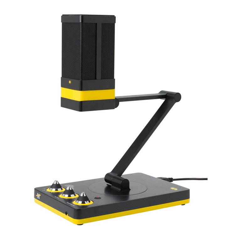
Neat Microphones Beecaster Field guide

Neat Microphones

Neat Microphones Beecaster Field guide

manuals.online logo
manuals.online logoBrands
  • About & Mission
  • Contact us
  • Privacy Policy
  • Terms and Conditions

Copyright 2025 Manuals.Online. All Rights Reserved.