AURES ODP 300 User manual

ODP300
Dot Printer
Technical manual

ODP300 Technical Manual
2
TABLE OF CONTENTS
1. General Specifications
Printing Specifications
Character Specifications
Auto Cutter
Paper Roll Supply Device
Paper Specification
Printable Area
Printing and Cutting Positions
Internal Buffer
Electrical Characteristics
EMI and Safety Standards Applied
Reliability
Environmental Conditions
2. Configuration
Interface
RS-232 serial interface
Specifications
Switching between on-line and off-line
Interface connector terminal assignments and signal functions
Serial interface connection example
Centronics parallel interface
Data Receiving Timing(Compatibility Mode)
USB Interface
Interface Connector
3. Connectors
Interface Connectors
Electrical Characteristics
Drawer kick-out Connector (Modular Connector)
4. Control Command Summary

ODP300 Technical Manual
3
1. General Specifications
1.1 Printing Specifications
1) Printing method: 9pin serial impact dot method
2) Printing direction: Bi-directional
3) Printing width: 63.5 mm (2.5")
4) No. of Columns: 42/35, 40/33 (EPSON TM-U200 Emulation)
40/33 (Others Emulation)
5) Printing speed: 5 lines/second
(at 40 Characters per line)
☞NOTE: Speeds are switched depending on the applied voltage to the printer and head temperature
conditions automatically.
6) Line spacing (default): n/144 inch
1.2 Character Specifications
1) Number of characters: Alphanumeric characters: 95
Extended graphics 128 × 7 pages
(including one space page)
International characters: 32
①English
②Hangul
③Chinese (GB2312,Big5)
④Kanji
2 ) Character structure: Font A: 7 ⅹ9
Font B: 9 ⅹ9
Font A is selected as the default

ODP300 Technical Manual
4
3) Print Format:
7 X9 Dots
9 X9 Dots
FONT
A
B
C
D
X
Y
Z
7 X9
0.397
1.19
1.49
1.998
0.352
2.11
2.46
9 X9
0.397
1.588
1.888
2.382
0.352
2.11
2.46

ODP300 Technical Manual
5
1.3 Auto Cutter
Partial cut: Cutting with one point center uncut
NOTE: To prevent dot displacement, after cutting, paper must be fed
approximately 1mm(14/360 inches) or more before printing.
1.4 Paper Roll Supply Device
1) Supply method: Drop-in paper roll
2) Near-end sensor:
a) Detection method: Photo Reflector
b) Paper roll spool diameter: Inside: 12.7mm(0.5″)
Outside: 18.4mm(0.72″)
d) Remaining amount: Fixed position #1 (approximately 23mm(0.9″))
#2 (approximately 27mm(1.06″))
NOTE: You can use a command to stop printing upon detection of a paper near-end.
1.5 Paper Specification
1) Paper type: Roll Paper
2) Paper width:
76.2 ±0.5mm (3.23" ±0.02")
69.5 ±0.5mm (2.74" ±0.02")
57.5 ±0.5mm (2.26" ±0.02")
3) Paper roll size: Roll diameter : Maximum 80mm
Take-up paper roll width:
76.2 ± 0.5, 1.0mm(3 "±0.020", 0.04")
4) Paper roll spool diameter: Inside: 12.7mm(0.5")
Outside: 18.4mm(0.72")
NOTE: Paper must not be pasted to the paper roll spool.

ODP300 Technical Manual
6
1.6 Printable Area
A
(Paper Width)
B
(Printable Area)
C
(Blank Area)
Left
Right
76.2 mm
63.2 mm (200dots,400positon)
7 mm
6 mm
69.5 mm
56.8 mm (180dots,360position)
7 mm
5.7 mm
57.5 mm
47.4 mm (150dot,300position)
6 mm
4.1 mm
ODP300 Technical Manual
7
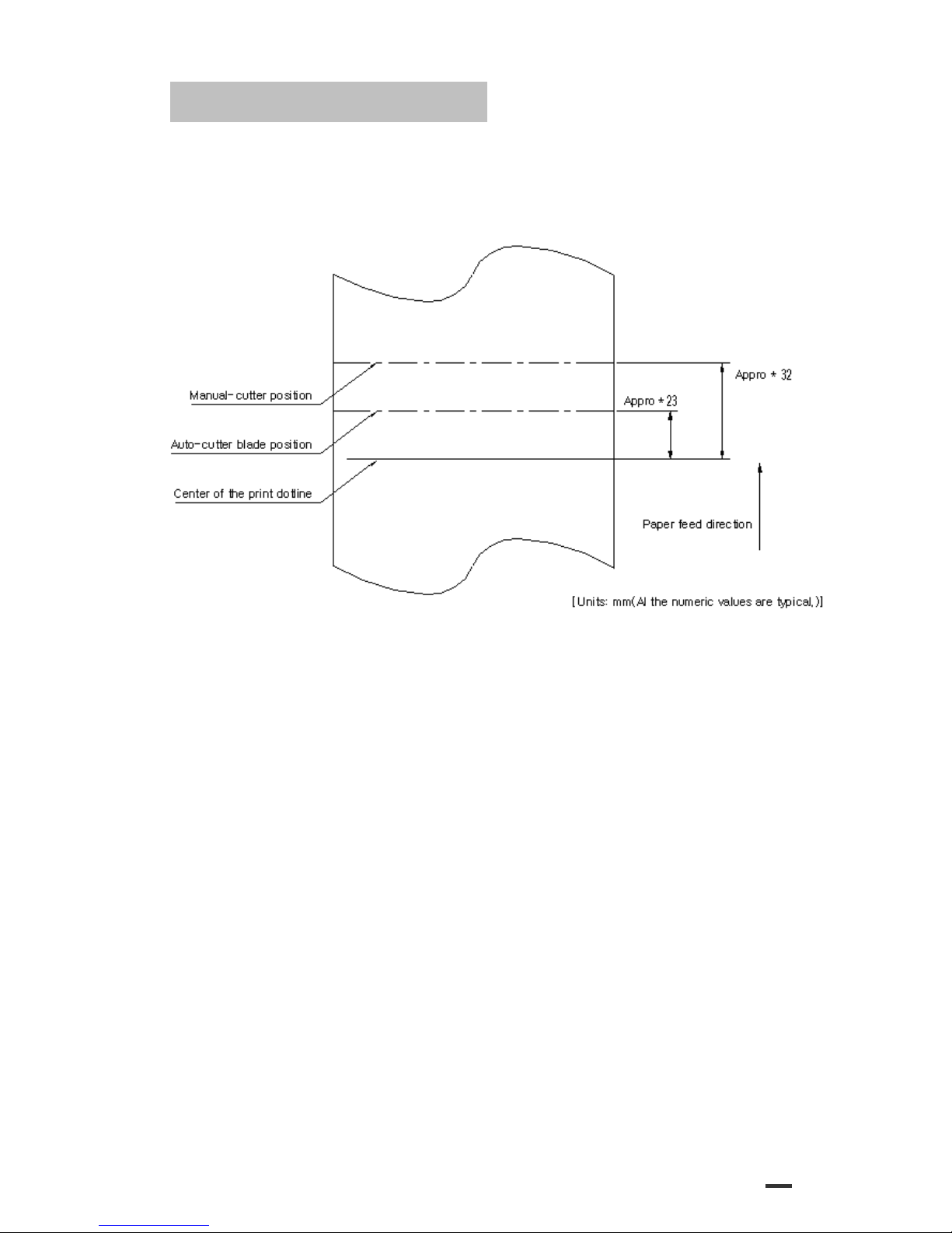
1.7 Printing and Cutting Positions
Figure 1.7.1 Printing and Cutting Positions
NOTE: Numeric values used here are center values to be used in designing. The values may vary slightly as a result of
paper slack or variations in the paper. Take this into account when setting the cutting position of the autocutter.

ODP300 Technical Manual
8
1.8 Internal Buffer
1) Data buffer: 16kbyte
1.9 Electrical Characteristics
1) 형태: 외부 아답터
2) 입력: 120VAC, 230VAC
3) 출력: 24VDC ⅹ2.5A
1.10 EMI and Safety Standards Applied
1) Europe: EMI –EN55022 CLASS A
EMS –EN61000-3-2, EN61000-3-3, EN50082-1
Safety Standard: EN60950
2) North America: EMI - FCC Part#15 Class A
Safety Standards- UL / c-UL(No.60950)
1.11 Reliability
1) MCBF: 18 million lines
2) Cutter Life: the cutter performs 1,000,000 cuts with thickness 65 ㎛, and/or 300,00cuts with
thickness 100 ㎛to the paper
3) HEAD 150 million characters
1.12 Environmental Conditions
1) Temperature: Operating: 5 to 40 C
Storage: -20 to 60 C
(except for paper)
2) Humidity: Operating: 10 to 80%RH
Storage: 5 to 95%RH (except for paper)

ODP300 Technical Manual
9
2. Configuration
2.1 Interface
2.1.1 RS-232 serial interface
2.1.2 Specifications
Data transmission: Serial
Synchronization: Asynchronous
Handshaking: DTR/DSR or XON/XOFF control
Signal levels: MARK= -3 to –15V: Logic “1”
SPACE= +3 to +15V: Logic “0”
Baud rage: 4800, 9600, 19200, 38400 bps
Data word length: 7 or 8 bits
Parity Settings: None, even, odd
Stop bits: 1 or more
Connector (printer side): Female DSUB-25 pin connector
NOTE: The data word length, baud rate, and parity depend on the
DIP switch settings.
2.1.3 Switching between on-line and off-line
The printer does not have an on-line/off-line switch.
The printer goes off-line:
•Between when the power is turned on (including reset using the interface) and when the
printer is ready to receive data.
•During the self-test.
•When the cover is open.
•During paper feeding using the paper feed button.
•When the printer stops printing due to a paper-end (in cases when an empty paper supply
is detected by either paper roll end detector or the paper roll near-end detector with a
printing halt feature by
ESC c4).
•During macro executing stand by status.
•When a temporary abnormality occurs in the power supply voltage.
•When an error has occurred.
2.1.4 Interface connector terminal assignments and signal functions
PIN
SIGNAL
I/O
DESCRIPTION
2
TXD
-
Printer transmit data line RS-232C level
3
RXD
-
Printer receive data line RS-232C level
4, 20
DTR
Output
Printer handshake to host line RS-232C level
6
DSR
Input
Data Send Ready
1,7
GND
-
System Ground

ODP300 Technical Manual
10
2.1.5 Serial interface connection example
Host side Printer side
TXD ………………………………… RXD
DSR ………………………………… DTR
RXD ………………………………… TXD
DTR ………………………………… DSR
FG ………………………………… FG
SG ………………………………… SG
DETAILS: ◦Set the handshaking so that the transmit data can be received.
◦Transmit data to the printer after turning on the power and initializing the printer.
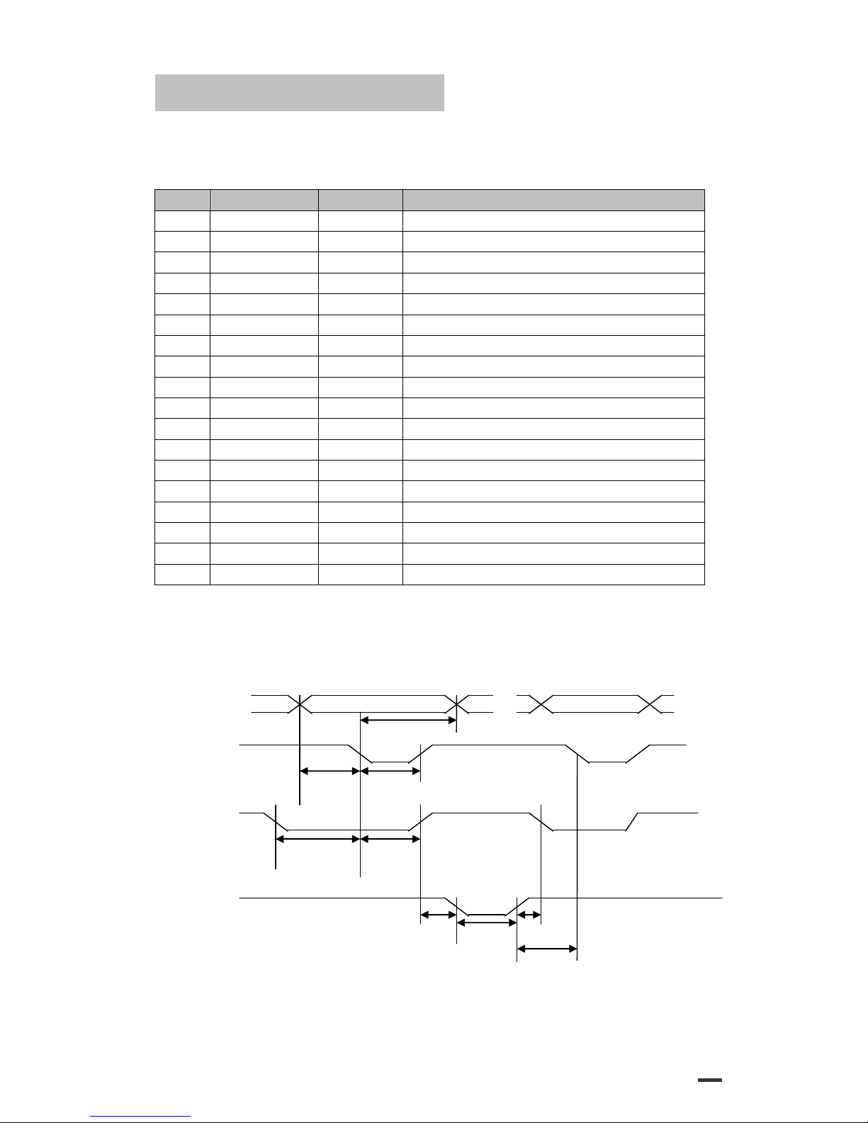
< Figure 2.1 Serial transmission bit frame >
< Figure 2.2 Line transmission with protocol >
1 Bit
7 or 8
Bit
None or
1 Bit
1 or 2
Bit
ODP300 Technical Manual
11
2.1.6 Centronics parallel interface
1) Specifications
Data transmission: 8-bit parallel
Synchronization: STROBE pulse supplied by host computer.
Handshaking: ACK and BUSY
Connector: D-SUB 36(female) or equivalent
DATA Data n Data n+1
tHold
nStrobe
tSetup tSTB
Busy Peripheral Busy
tReady tBUSY
nAck
tReply tACK tnBUSY
tNext
PIN
SIGNAL
I/O
DESCRIPTION
1
STROBE-
Input
Synchronize signal Data received
2-9
DATA0-7
Input
Data bit Transmitted 0-7
10
ACK-
Output
Data receiving competed
11
BUSY
Output
Impossible to printer data receiving
12
PE
Output
Paper empty
13
SELECT
Output
Printer’s status for ON/OFF line
14
AUTO FEED-
Input
ND
15
GROUND
-
System Ground
16
GROUND
-
System Ground
17
NC
-
18
LOGIC-H
-
+5V
19-30
GROUND
-
System Ground
31
INIT-
Input
Initialize
32
ERROR-
Output
Printer Error
33
GROUND
-
System Ground
34
NC
-
35
+5V
-
+5V
36
SELECT IN-
Input
ND

ODP300 Technical Manual
12
2.1.7 Data Receiving Timing (Compatibility Mode)
Characteristics
Symbol
Specifications
Min [ns]
Max [ns]
Data Hold Time (host)
tHold
750
--
Data Setup Time
tSetup
750
--
STROBE Pulse Width
tSTB
750
--
READY Cycle Idle Time
tReady
0
--
BUSY Output Delay Time
tBUSY
0
500
Data Processing Time
tReply
0
ACKNLG Pulse Width
tACK
500
10us
BUSY Release Time
tnBUSY
0
ACK Cycle Idle Time
tNEXT
0
--
The printer latches data at a nStrobe ↓timing
2.1.8 USB Interface
PIN
SIGNAL
I/O
DESCRIPTION
1
+5V
-
+5V
2
DATA-
-
Printer transmit data line
3
DATA+
-
Printer transmit data line
4
GND
-
System Ground
1) Specifications
Data transmission: USB 2.0
Connector: USB “B” type connector
2) USB interface connection example
Host side Printer side
VCC ………………………………… VCC
DATA+ ……………………………… DATA+
DATA- ……………………………… DATA-
GND ………………………………… GND
ODP300 Technical Manual
13
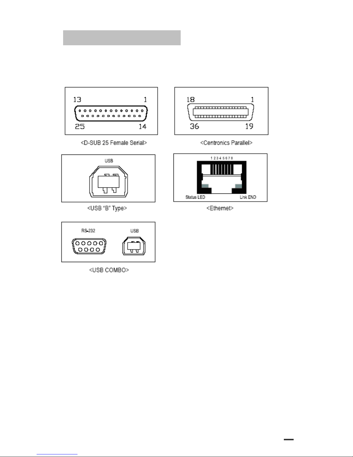
2.1.9 Interface Connector
ODP300 Technical Manual
14
3. Connectors
3.1 Interface Connectors
Refer to Section 2.1, Interface
3.2 Electrical Characteristics
1) Input Voltage: DC 24V ± 10%
2) Current Consumption: Operating: Approx. 1.5 A (at ASC∥printing)
Peak: Approx. 10 A (at print duty 100%, For 10 seconds or less)
Stand-by: Approx. 0.15 A
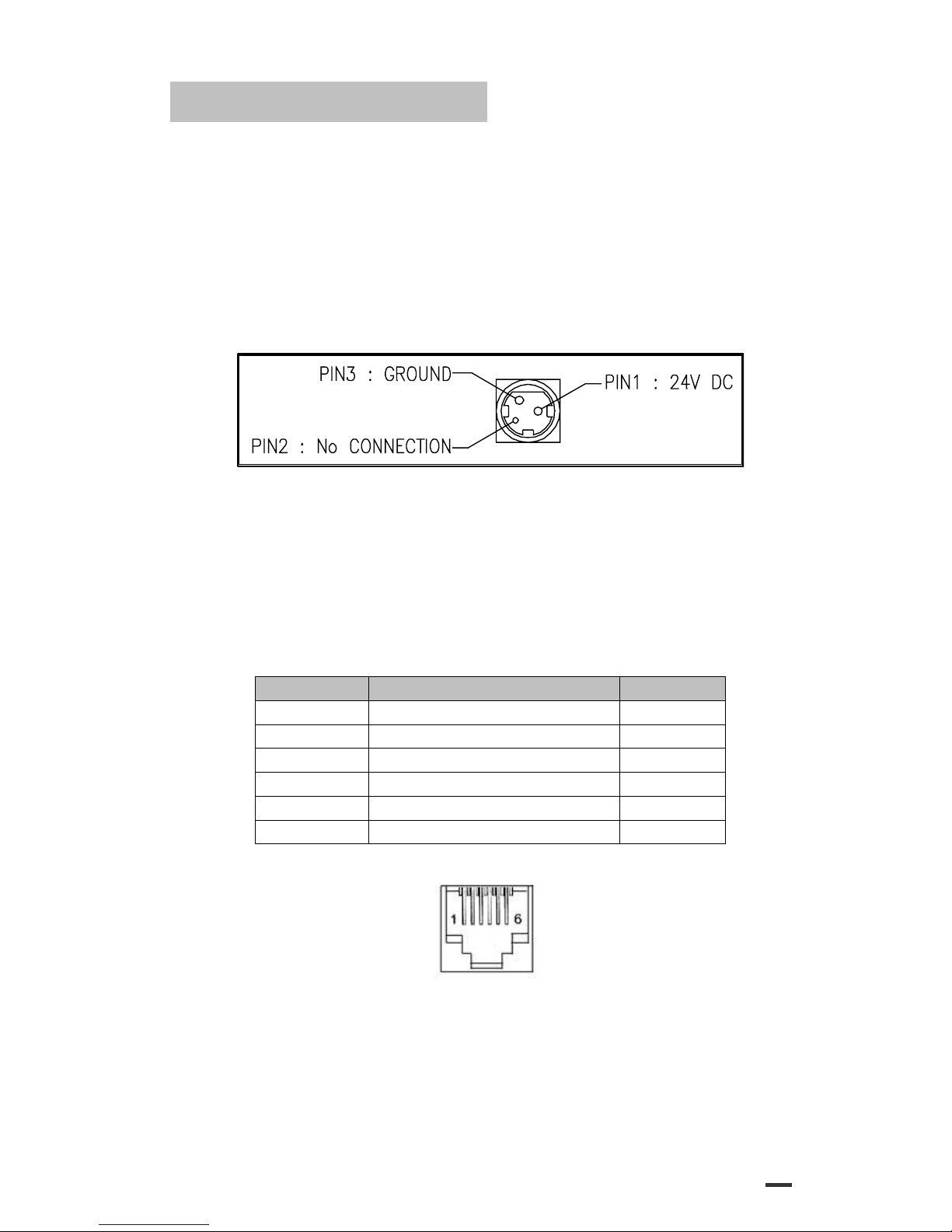
3) Power Connector
3.3 Drawer Kick-out Connector (Modular Connector)
The pulse specified by ESC p or DLE DC4 is output to this connector.
The host can confirm the status of the input signal by using the
DLE EOT,GS a, or GS r commands.
1) Pin assignments: Refer to Table 2.2.2
2) Connector model:
Printer side: DAEEUN DEK-623PCB-6-B or Equivalent
User side: 6-position 6-contact (RJ12telephone jack)
< Drawer Kick-out Connector Pin Assignments >
Pin Number
Signal Name
Direction
1
Frame GND
-
2
Drawer kick-out drive signal 1
Output
3
Drawer open/close signal
Input
4
+24V
-
5
Drawer kick-out drive signal 2
Output
6
Signal GND
-
+24V is output through pin 4 when the power is turned on. However, pin 4 must by used only for the drawer.
< Figure 3.1 Drawer Kick-out Connector >
3) Drawer kick-out drive signal
Output signal: Output voltage: Approximately 24V
Output current: 1A or less

ODP300 Technical Manual
15
CAUTION: To avoid an overcurrent, the resistance of the drawer kick-out solenoid
must be 24 Ω or more.
Output waveform: Outputs the waveforms in Figure 3.2 to the points A and B
in Figure 3.3
t1 (ON time) and t2 (OFF time) are specified by ESC p or
DLE DC4.
< Figure 3.2 Drawer Kick-out Drive Signal Output Waveform >
4) Drawer open/close signal
Input signal level (connector pin 3): “L”= 0 to 0.8V
“H”= 3 to 5V
< Figure 3.3 Drawer Circuitry >
NOTE: 1. Use a shielded cable for the drawer connector cable.
2. Two driver transistors cannot be energized simultaneously.
3. The drawer drive duty must by as shown below.
ON time
≤ 0.2
(ON time + OFF time)
4. Be sure to use the printer power supply (connector pin 4) for the drawer power source.
5. The resistance of the drawer kick-out solenoid must not be less than the specified. Otherwise, an
overcurrent could damage the solenoid.
6. Do not connect telecommunication network to the drawer kick-out connector.
Other manuals for ODP 300
1
Table of contents
Other AURES Printer manuals

AURES
AURES ODP-200H-III User manual

AURES
AURES ODP 444 User manual

AURES
AURES Posligne ODP-1000 User manual

AURES
AURES SMP 58 Instruction sheet

AURES
AURES SMP 58 User manual

AURES
AURES TRP100 User manual

AURES
AURES TRP100-III User manual

AURES
AURES ODP 300 User manual

AURES
AURES TRP100 User manual

AURES
AURES SLP 580 User manual


