Aurora DXE-CAT-S2L User manual

i
Manual Number: 120709
USERS GUIDE
DXE-CAT-S2L
HDMI HDBaseT CAT Extender with IP Control

i
User Guide
SAFETY INSTRUCTIONS
Please review the following safety precautions. If this is the first time using this model, then read this
manual before installing or using the product. If the product is not functioning properly, please contact
your local dealer or Aurora for further instructions.
The lightning symbol in the triangle is used to alert you to the presence of dangerous voltage
inside the product that may be sufficient to constitute a risk of electric shock to anyone opening
the case. It is also used to indicate improper installation or handling of the product that could
damage the electrical system in the product or in other equipment attached to the product.
The exclamation point in the triangle is used to alert you to important operating and maintenance
instructions. Failure to follow these instructions could result in injury to you or damage to the
product.
Be careful with electricity:
Power outlet: To prevent electric shock, be sure the electrical plug used on the product power cord
matches the electrical outlet used to supply power to the Aurora product. Use only the power adapter
and power connection cables designed for this unit.
Power cord: Be sure the power cord is routed so that it will not be stepped on or pinched by heavy
items.
Lightning: For protection from lightning or when the product is left unattended for a long period,
disconnect it from the power source.
.
Also follow these precautions:
Ventilation: Do not block the ventilation slots if applicable on the product or place any heavy object
on top of it.
Blocking the air flow could cause damage. Arrange components so that air can flow freely. Ensure
that there is adequate ventilation if the product is placed in a stand or cabinet. Put the product in a
properly ventilated area, away from direct sunlight or any source of heat.
Overheating: Avoid stacking the Aurora product on top of a hot component such as a power
amplifier.
Risk of Fire: Do not place unit on top of any easily combustible material, such as carpet or fabric.
Proper Connections: Be sure all cables and equipment are connected to the unit as described in
this manual.
Object Entry: To avoid electric shock, never stick anything in the slots on the case or remove the
cover.
Water Exposure: To reduce the risk of fire or electric shock, do not expose to rain or moisture.
Cleaning: Do not use liquid or aerosol cleaners to clean this unit. Always unplug the power to the
device before cleaning.
ESD: Handle this unit with proper ESD care. Failure to do so can result in failure.
FCC
This device complies with Part 15 of the FCC Rules. Operation is subject to the following two conditions:
(1) This device may not cause harmful interference.
(2) This device must accept any interferences received, including interference that may cause undesired
operation.
Trademarks
All trademarks in this document are the properties of their respective owners.

ii
User Guide
TABLE OF CONTENTS
PACKAGE CONTENTS .............................................................................................................1
INTRODUCTION........................................................................................................................2
About..................................................................................................................................................... 2
Features................................................................................................................................................ 2
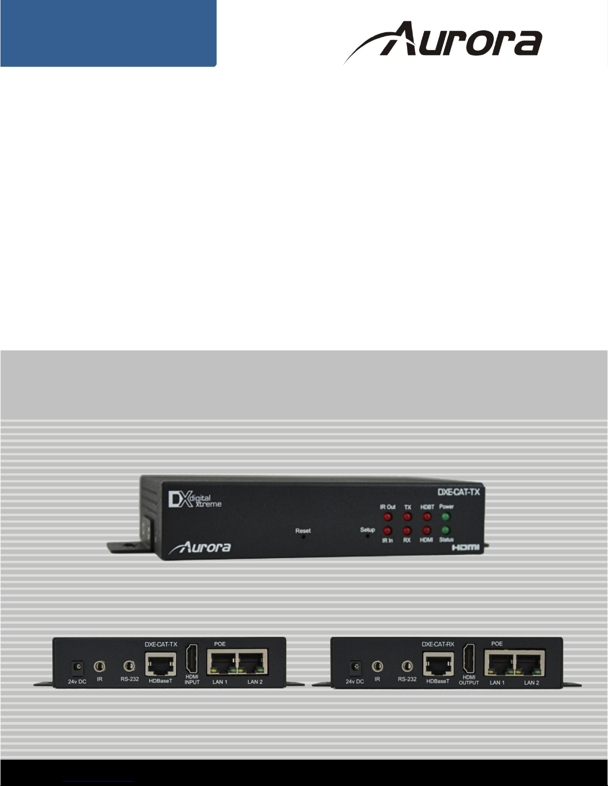
Front & Rear Panel DXE-CAT-TX2L..................................................................................................... 3
Front & Rear Panel DXE-CAT-RX2 ...................................................................................................... 4
IR EXTENDERS.........................................................................................................................5
IR Connections ..................................................................................................................................... 5
IR Jack Pinout....................................................................................................................................... 5
Default IP .............................................................................................................................................. 6
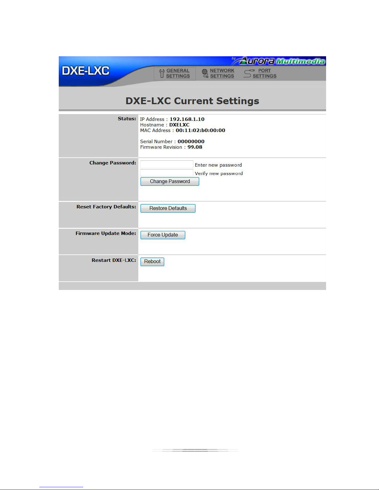
General Settings ................................................................................................................................... 7
Network Settings................................................................................................................................... 8
Port Settings ......................................................................................................................................... 9
Port Settings (Manual) .........................................................................................................................11
Port Settings (Push to Variable).......................................................................................................... 12
Port Settings (Telnet Server)............................................................................................................... 13
Port Settings (Telnet Client) ................................................................................................................ 14
Port Settings (Push to Port) ................................................................................................................ 15
Port Settings (Pass-Through) ............................................................................................................. 16
IP Commands .........................................................................................................................17
TCP/RPC Commands......................................................................................................................... 17
TCP/RPC Command Usage ............................................................................................................... 18
Web Server .............................................................................................................................19
CONNECTOR PIN DEFINITION ..............................................................................................20
HDMI................................................................................................................................................... 20
CAT5e/6/7 ........................................................................................................................................... 20
APPENDIX 1 Troubleshooting...........................................................................................21
APPENDIX 2 Firmware Update..........................................................................................21
APPENDIX 3 Technical Specifications..............................................................................22
APPENDIX 4 Warranty .......................................................................................................23

1
User Guide
PACKAGE CONTENTS
Please make sure the following items are included within your package. Contact your dealer if any items
are missing or damaged.
DXE-CAT-RX2 x 1
DXE-CAT-TX2L x 1
DXE-CAT-E1 Wall / Desk Mount Ears x 4
24V DC Power Adapter x 1
Optional Accessories
IR Receiver CA0026-1
IR Emitter CA0012-1
IR Blaster CA0049-1
Note: Go to www.auroramultimedia.com for latest manual and firmware

2
User Guide
INTRODUCTION
About
The DXE-CAT-S2L is part of the growing Digital Xtreme Series. This product is different than the
typical CAT extender found on the market today as it not only breaks the price barrier but the
feature and usability aspects as well. All connectors are on one side to make wiring cleaner and
rack mounting easier. Having the ability to power the device with the choice of transmit or receive
reduces the installation time and keeps things neat. An industry first is Aurora’s exclusive
Flex-PowerTM Power-Over-Ethernet circuit (Patents Pending), which allows both the transmitter
and receiver to be powered without the need of any wall supplies.
The DXE-CAT-S2L is also unique as it combines IP control with an extender. Normally extenders
simply pass the RS-232 and IR from one device to the other, however, the DXE-CAT-S2L can
target a local or far end port via TCP, RPC, or Telnet commands from any control system or PC
on the market. It also has the ability to serve up web pages via the LAN port to any device with a
web browser.
Being able to go the distance is important too, and HDBaseT technology helps achieve that. With
a single CAT cable, the DXE-CAT can go up to 330ft 1080p 60Hz 48bit color depth depending on
model. In addition, the RS-232, IR, & LAN can be sent over the same cable bi-directionally.
Features
Transmit HDMI up to 1080p 60Hz 48bit 330ft over one CAT 5e/6/7 cable
Supports 4K x 2K & HDMI 3D
HDCP Compliant
IP Control System (32 bit)
Web Server with 8MB of Storage
All connectors on one side for easier installation
Bi-directional RS-232 & IR & LAN
Power both units from TX or RX side with wall power supply (HDBaseT POE)
LAN POE (Power-Over-Ethernet) can power both TX & RX without wall supplies (Patents
Pending)
Status LED for all connections on front
Various mounting options

3
User Guide
Front & Rear Panel DXE-CAT-TX2L
Front LED Indicators
•IR Out – Blinks when emitting IR to device from IR Port. It is normal to be lit if nothing is plug
into IR port.
•IR In – Blinks when receiving IR from IR port. It is normal to be lit if nothing is plug into IR port.
•TX – RS-232 Transmit. Blinking rate and intensity will vary with baud rate.
•RX – RS-232 Receive. Blinking rate and intensity will vary with baud rate.
•HDBT – Lights when HDBaseT RJ-45 has proper connection between an RX/TX pair. Blinks
when in sleep mode.
•HDMI – Will light solid if HDMI is plugged in on both RX/TX and HDCP is present. If no HDCP
LED will blink.
•POWER – Lights green when power is present.
•STATUS – Will blink steady if unit is working properly.
Front Pin-hole buttons
•Reset – Use paper clip or similar object to reset unit by pushing into hole.
•Setup – Press and hold for 3 seconds to restore factory defaults. (refer to IP settings section).
Rear Connections
•24V DC – Power connector for 15 watt 24VDC power supply. Note only 1 supply is required to
power both units. Either side can send power to the other unit. Note if LAN POE is utilized the
24VDC supply is not required.
•IR – Plug the IR receiver or emitter into this port. It will auto detect the mode of operation
required.
•RS-232 – Connect RS-232 device up to 115k baud.
•HDBaseT – Connect CAT 5e/6/7 cable. Shield cable is not necessary unless the environment
has a lot of electrically noise.
•HDMI Input – Plug HDMI cable from source device like a BluRay player. Note the HDMI cable
should be rated for the bandwidth you are using.
•LAN1/2 – 10/100 LAN connection. LAN1 can use POE from a POE switch to power both the
RX and TX units. Note: HDBaseT can only transmit 10T from the LAN.
Note: Some POE switch do not supply the full 15.4watts per port. Verify the total power rating of the switch. It should
be at least 15.4W x (number of ports).

4
User Guide
Front & Rear Panel DXE-CAT-RX2
Front LED Indicators
•IR Out – Blinks when emitting IR to device from IR Port. It is normal to be lit if nothing is plug
into IR port.
•IR In – Blinks when receiving IR from IR port. It is normal to be lit if nothing is plug into IR port.
•TX – RS-232 Transmit. Blinking rate and intensity will vary with baud rate.
•RX – RS-232 Receive. Blinking rate and intensity will vary with baud rate.
•HDBT – Lights when HDBaseT RJ-45 has proper connection between an RX/TX pair. Blinks
when in sleep mode.
•HDMI – Will light solid if HDMI is plugged in on both RX/TX and HDCP is present. If no HDCP
LED will blink.
•POWER – Lights green when power is present.
•STATUS – Will blink steady if unit is working properly.
Front Pin-hole buttons
•Reset – Use paper clip or similar object to reset unit by pushing into hole.
•Setup – For DXE-CAT-TX2L model only. Not used for DXE-CAT-RX2.
Rear Connections
•24V DC – Power connector for 15 watt 24VDC power supply. Note only 1 supply is required to
power both units. Either side can send power to the other unit. Note if LAN POE is utilized the
24VDC supply is not required.
•IR – Plug the IR receiver or emitter into this port. It will auto detect the mode of operation
required.
•RS-232 – Connect RS-232 device up to 115k baud.
•HDBaseT – Connect CAT 5e/6/7 cable. Shield cable is not necessary unless the environment
has a lot of electrically noise.
•HDMI Output – Plug HDMI cable from destination device like an LCD display. Note the HDMI
cable should be rated for the bandwidth you are using.
•LAN1/2 – 10/100 LAN connection. LAN1 can use POE from a POE switch to power both the
RX and TX units. Note: HDBaseT can only transmit 10T from the LAN.
Note: Some POE switch do not supply the full 15.4watts per port. Verify the total power rating of the switch. It should
be at least 15.4W x (number of ports).

5
User Guide
IR EXTENDERS
IR Blaster IR Receiver
IR Connections
The DXE-CAT Series has the ability to auto detect on the IR port if a receiver or a blaster / emitter is connected.
IR Blaster / Emitter: Plug in an IR blaster to emit all IR command signals received from the IR receiver to control the associated
devices with built-in IR sensor
IR Receiver: Plug in an IR receiver to receive all IR command signals from the IR remote controls of the associated devices.
Note if you are not using an approved Aurora branded receiver make certain you do not exceed the 5v signal level
limitation as some devices use 12v. Failure to do so will result in damage.
When the DXE-CAT-TX2L is set for manual the only way to send IR commands is using IR files loaded on the ftp of the unit in the
IR directory. Aurora IR files (.wir) are available for download on the Aurora website. In addition, IR files learned from NX or QX
control devices can be utilized.
IR Jack Pinout
IR Blaster IR Receiver
Emitters must be mono plug or have ring and sleeve tied to ground.
Receivers must be stereo plug. Ring is 5v power. If using another brand receiver,
note carrier frequency must be stripped and IR signal cannot exceed 5v or
damage to port may occur.

6
User Guide
IP Setup
Default IP
The default IP out of the box is 192.168.1.10 static. Make certain to change the IP on the unit at
a time or you will get collisions on the network. Each device must have a unique IP address.
DHCP can be used but it is recommended to issue IP address based on the MAC address. This
assures the DHCP does not reassign the IP address at a later time causing issues. Keep in
mind the processor is on the TX unit so only the TX needs to be connected when you are doing
the initial setup although having the RX will not affect the process and may be necessary only if
the LAN is connected at the RX side.
The default user name is admin and the default password is admin.
In the event you lose your settings press and hold the setup button on the DXE-CAT-TX2L for 3
seconds. This will restore the unit back to factory default.

7
User Guide
General Settings
Status - Shows the current IP Address, Hostname, Mac Address, Serial number, and the firmware
revision.
Change Password – The default password is admin. It is recommend to change the password for better
security on the network especially if it is not private.
Reset Factory Defaults – Once pressed a confirm screen will appear. Once confirmed the unit will
restore the default IP address and password.
Firmware Update Mode – This but forces the unit into an update mode. It is recommended to use the
firmware update tool LXupdate which is available on the Aurora website.
Restart DXE-LXC – Remotely reboots the unit.

8
User Guide
Network Settings
Current Network Settings - Shows the current IP Address, Subnet Mask, Gateway, Hostname, and
Mac Address.
Network Configuration – This section allows the turning on/off of the DHCP and allowing the entry of
static IP settings if DHCP is not utilized. If you use DHCP it is always recommended to use a switch that
can map the MAC address to a defined IP address otherwise the IP address may change inadvertently at
a later time making it difficult to target the device. Hostname can only be utilized on a NETBIOS system.
If TCP commands are used there is a setting for the TCP server port number. Make certain once done
making changes to press apply changes.

9
User Guide
Port Settings
Master Remote IP – Enter the Aurora control system IP the DXE-LXC is going to push information to.
Note: If an Aurora control system is not used RPC, Telnet, or TCP is available.
Local Serial Port 1 Settings – Baud Rate, Date Size, Parity, and Stop bits are selected for the TX
RS-232 port.
Remote Serial Port 2 Settings – Baud Rate, Date Size, Parity, and Stop bits are selected for the RX
RS-232 port.

10
User Guide
Port Processing Session – Choose between the following modes of operation.
Manual - Ports are just serial ports manipulated via RPC / Telnet / TCP commands.
Push to Variable - RX data is pushed via Aurora RPC to given Master Remote IP.
Push to Port - RX data is pushed to given IP remote serial port via Aurora RPC.
Telnet Client - Unit will attempt to connect to given server IP and pass and receive serial port data.
Telnet Server - Unit will wait for external connection to pass and receive serial port data.
Pass-Through - Unit’s (TX/RX) serial ports are linked so any serial RX data will come out the TX on
the other serial port.
Test Serial Transmit – Enter a serial string to send out the RS-232 port for testing of connecting device.
IR Ports – Selecting the activate IR repeater mode enables the transfer of the IR ports signals to and
from the TX and RX units. If it is not selected only RPC / Telnet / TCP commands will trigger the IR ports
locally or remotely. IR files are stored on the ftp of the DXE-CAT-TX2L unit in the IR folder.

11
User Guide
Port Settings (Manual)
With port processing session set to manual there will be no additional selections as the system is set to
trigger the functionality with IP commands. Ports will not pass data from the TX to RX and vice versa in
this mode.

12
User Guide
Port Settings (Push to Variable)
Remote Session IP Address – Enter the IP address the variable is to be sent to an Aurora control
device. Note the IP address overrides the Master Remote IP address.
Target RPC Variable Name – Enter the variable utilized by the remote control processor.

13
User Guide
Port Settings (Telnet Server)
Telnet Local Port Number – Defaulted to Port 23 but can be changed to other port numbers.
Telnet Timeout Seconds – Defaulted to no timeout but can be set to timeout and close the connection.
Telnet Protocol – Default is Telnet otherwise it can be set to none which is used for TCP.

14
User Guide
Port Settings (Telnet Client)
Remote Session IP Address – Enter Telnet Server IP Address.
Telnet Remote Port Number – Defaulted to Port 23 but can be changed to other port numbers.
Telnet Local Port Number – Defaulted to Port 23 but can be changed to other port numbers.
Telnet Timeout Seconds – Defaulted to no timeout but can be set to timeout and close the connection.
Telnet Protocol – Default is Telnet otherwise it can be set to none which is used for TCP.

15
User Guide
Port Settings (Push to Port)
Remote Session IP Address – Enter IP address of serial port on another Aurora control device to target.
This will forward the serial data to any Aurora control system product. It overrides the master Remote IP.
Target RPC Serial Port Number – Enter the serial port number of the Aurora control device.

16
User Guide
Port Settings (Pass-Through)
Pass-Through mode allows the serial ports on both the DXE-CAT-TX and DXE-CAT-RX to become a
virtual cable link.The serial receive of one unit will be sent to the serial transmit of the other unit. IP
commands will still force serial strings out the local or remote ports when necessary.

17
User Guide
IP Commands
TCP/RPC Commands
Remote procedure calls (RPCs) are used to control the DXE-CAT-S2L from any device with a web
browser (PC, iPad, touch panel, etc.), an external control system, or another web-enabled device. RPCs
can be used to send serial and IR commands, receive serial data, and retrieve system information.
RPCs can be sent in the form of an HTTP POST (used for web based control pages or control from a
Aurora WACI series controller) or TCP commands (used for control from an external control system).
Calls to the RPC server using HTTP POST are done through the /rpc virtual directory, e.g.
http://ip-address/rpc. Use this directory as part of the URL when creating the address for the HTTP POST
transaction. TCP commands are structured the same way as the HTTP POST, but sent over a raw TCP
connection without any HTTP headers.
Command
Description
GetFirmwareVersion ( )
Returns the firmware version
GetSerialNumber ( )
Returns the serial number
Net_GetIPAddress ( )
Returns the IP address
Net_GetSubnetMask ( )
Returns the subnet mask
Net_GetNetCardCount ( )
Returns the number of network ports on the unit
Serial_GetSettings ( Port )
Returns the settings of a specific serial port 1
Serial_Send ( Port, Msg, MaxWaitMS )
Sends a serial command to a specific port 12
MaxWaitMS = The number of milliseconds allowed to complete the sending of the
serial data before timing out
GetWebFileNames ( )
Returns the names of the web files
GetIRFileNames ( )
Returns the names of the IR files
Serial_Read ( Port )
Reads the serial buffer for a specific serial port 12
Serial_ClearReadBuffer ( Port )
Clears the serial buffer for a specific port 1
Serial_ReadBufferCount ( Port )
Reads the buffer count for a specific port 1
Serial_GetPortCount ( )
Returns the total number of available serial ports (2) 1
IR_GetPortCount ( )
Returns the total number of available IR ports (2) 1
IR_SendCommand ( Port, Group, Command )
Sends an IR command from the specified port 1
Group = The IR file name
Command = The IR command name
IR_ListAllGroups ( )
Returns all loaded IR groups (files)
IR_ListAllCommandsInGroup ( Group )
Returns all IR commands in a specific group
GetMachineType ( )
Returns the ID of the DXE-CAT-S2L controller (used for
communication with other Aurora controllers)
SetDefaultConfig ( )
Resets the DXE-CAT-S2L settings to factory default
1 Serial port 1 / IR port 1 is located on the DXE-CAT-S2L TX unit, serial port 2 / IR port 2 is located on the RX unit
2Hexadecimal data is represented with a percent sign preceding the 2-byte hex code (e.g. %0D for carriage return)
Table of contents
Other Aurora Extender manuals

Aurora
Aurora DXE-CAT-S2 User manual

Aurora
Aurora DXE-CAT-S2C-4K User manual

Aurora
Aurora HT Pro Series User manual

Aurora
Aurora DXE-USB Series User manual

Aurora
Aurora ASP-HDB1 User manual

Aurora
Aurora DXE-CAT-S2C User manual

Aurora
Aurora Digital Xtreme Series User manual

Aurora
Aurora DXE-CAT-S1 User manual

Aurora
Aurora DXE-CAT-S1-4K User manual

Aurora
Aurora HDBT HT Series User manual