AUSA CH 200 User manual

MANUAL DE
SERVICIO HIDRÁULICO
HYDRAULIC SERVICE
MANUAL
Distribuidor
Distributor
Dirección hidraulica
Hydraulic steering
Grupo hidrostático
Hydrostatic group
CH 200
CH 250
CH 200
CH 250
ESPAÑOL / ENGLISH


CH 200
CH 250


3
Prólogo
Prologue
nGracias por escoger este modelo de carretilla elevadora AUSA, que le ofrece lo mejor, en
cuanto a rentabilidad, seguridad y confort de trabajo se refiere. Conservar estas características
durante mucho tiempo, esta en sus manos, haga un uso correcto de la carretilla para aprovechar
sus consiguientes ventajas.
Se recomienda leer y comprender este Manual antes de operar con la carretilla, su propósi-
to es instruir a las personas en contacto con la carretilla y especialmente al operador. Su con-
tenido le ayudara a conocer mejor su carretilla AUSA, a saber todo lo referente a su puesta en
marcha, modo de conducción, mantenimiento, conservación, usos previstos de la misma e
instrucciones de seguridad que se deben tener en cuenta.
Cualquier daño ocasionado por una utilización indebida, no podrá considerarse respons-
abilidad de AUSA.
Ante cualquier duda, reclamación o pedidos de recambios contacte con su Agente Oficial -
Distribuidor AUSA.
Para mayor información diríjase a:
nAUSA está continuamente mejorando sus productos y se reserva el derecho a efectuar las
oportunas modificaciones, sin incurrir en la obligación de introducirlas en las máquinas vendidas
con anterioridad. Por lo tanto no se pueden presentar reclamaciones basándose en los datos,
ilustraciones y descripciones de este manual.
Utilice únicamente piezas de recambio originales AUSA. Sólo así se garantiza que su
máquina AUSA siga conservando el mismo nivel técnico que en el momento de la entrega.
No debe efectuarse ningún tipo de modificación en la máquina, sin previa auto- rización del
fabricante.
Guarde este manual en la guantera situada a la derecha del asiento, debajo del apoya-bra-
zos.
AUTOMOVILES UTILITARIOS, S.A.AUTOMOVILES UTILITARIOS, S.A.
Apartado P.O.B. 194
08240 MANRESA (Barcelona) SPAIN
Tel. 34 - 93 874 75 52 / 93 874 73 11
Fax 34 - 93 873 61 39 / 93 874 12 11 / 93 874 12 55
Web: http://www.ausa.com
nThank you for choosing this AUSA. The purpose of this Operators Manual is to provide you, the
user, with instructions concerning the productive, safe and efficient use of this forklift. You should
read and understand this manual before operating the forklift. The Manual contains safety mes-
sages concerning the use of the forklift. Remember that “you” are the key to safety.
The Manual also contains instructions for some adjustments and for maintenance of this CE11
Forklift. Follow this instructions carefully while performing routine maintenance checks and keep a
record of all maintenance. As wide variations in operating conditions may be experienced, you are
urged to contact your AUSA Distributor to resolve any operational or service problems.
Please have all operators of this forklift read and understand this Manual.
When not in use keep it stored on the forklift in the Manual holder box under the chassis on its
left side.
The CE11 Forklift is designed and intended for off highway use. If it is temporarily operated on
any public street or highway, the state and local laws governing speed, size, weight, brakes and
lighting must be complied with.
For further information you may write, FAX or E-mail to:
nAUSA is continuously trying to improve the efficiency, productivity and safety of its products and
reserves the right to make such improvements without incurring any obligation to make changes to
forklifts previously sold.
Because of this policy of striving for constant product improvement, the specifications and ope-
rating instructions shown in this Manual may be different from prior forklift models.
AUTOMOVILES UTILITARIOS, S.A.AUTOMOVILES UTILITARIOS, S.A.
Apartado P.O.B. 194
08240 MANRESA (Barcelona) SPAIN
Tel. 34 - 93 874 75 52 / 93 874 73 11
Fax 34 - 93 873 61 39 / 93 874 12 11 / 93 874 12 55
Web: http://www.ausa.com

Indice
Index
4
Introducción
Foreward
Características Técnicas
Technical features
Operaciones periódicas de Mantenimiento
Periodical Maintenance Operations
Regulación de la válvula de seguridad del distribuidor
Setting the safety valve of the slide-valve
Regulación de la válvula de seguridad de la dirección hidráulica
Setting the safety valve of the distributor
Tomas de presión y manómetros grupo hidrostático
Pressure intakes and manometer of the hydrostatic group
Presión de alimentación del grupo hidrostático
Charge pressure of the hydrostatic group
Presión de trabajo del grupo hidrostático
Working pressure of the hydrostatic group
Cuadro de Mantenimiento
Maintenance chart
5
6
7
12
14
13
11
10
9

5
Introducción
Foreward
nExisten dos válvulas de seguridad para evitar sobrepresiones en el circuito de la
dirección y en el de accionamientos del mástil. Estas válvulas se regulan en fábrica
a la presión correcta, pero periódicamente se debería comprobar su regulación y en
caso necesario regular de nuevo. Esta operación tiene que ser efectuada por per-
sonal con amplios conocimientos de hidráulica y con las herramientas adecuadas.
Las presiones nunca deben exceder de las indicadas.
nThere are safety relief valves on both the hydraulic steering block and on the load
handling control valve. Although they are set at the correct working pressure at the
factory, if the hydraulic system fails these safety valves must be reset. However this
work must only be done by trained mechanics with knowledge of hydraulics and cor-
rect pressure gauge tools. The pressure must not be set higher than set forth in this
Hydraulic Service Manual.

Características
técnicas
Technical
features
6
nCircuito hidráulico.
Una bomba de engranajes doble acoplada a la bomba de la transmisión para la
dirección hidráulica de 8cc y para el circuito de accionamientos de 18cc. Un dis-
tribuidor monobloque de dos correderas y electroválvula selectora.
Válvula de frenado para controlar la velocidad de bajada del mástil con carga.
Depósito de aceite hidráulico de 47 l.
nDirección.
Sistema "ORBITROL", el accionamiento es efectuado por un cilindro de doble vásta-
go en el eje trasero.
nCircuito hidrostático.
Bomba y motor "REXROTH", con inching (aproximación lenta).
CH - 200 y CH - 200 x 4: Motor hidrostático de dos velocidades, controladas
eléctricamente por un pulsador.
CH - 250 y CH - 250 x 4: Motor hidrostático de caudal variable.
nHydraulic circuit
A double gear pump driven by the hydrostatic pump, with a displacement of 8cc
for the hydraulic steering and 18cc for hydraulic equipment. Two spool valve
block.
Maximum load lowering speed controlled by check valve.
Hydraulic tank capacity: 12.4 US gal or 10.3 UK gal
nSteering
Hydraulic "orbitrol" system powered with one double acting hydraulic cylinder on the
rear axle.
nHydrostatic transmission
"REXROTH" pump and motor with “Inching”.
CH - 200 y CH - 200 x 4: Hydrostatic motor two speeds selected by electric switch.
CH - 250 y CH - 250 x 4: Hydrostatic motor variable flow .
7
nEn las operaciones de mantenimiento utilice únicamente recambios origi-
nales AUSA. Sólo así garantizará que su máquina siga conservando el mismo
nivel técnico que en el momento de la entrega.
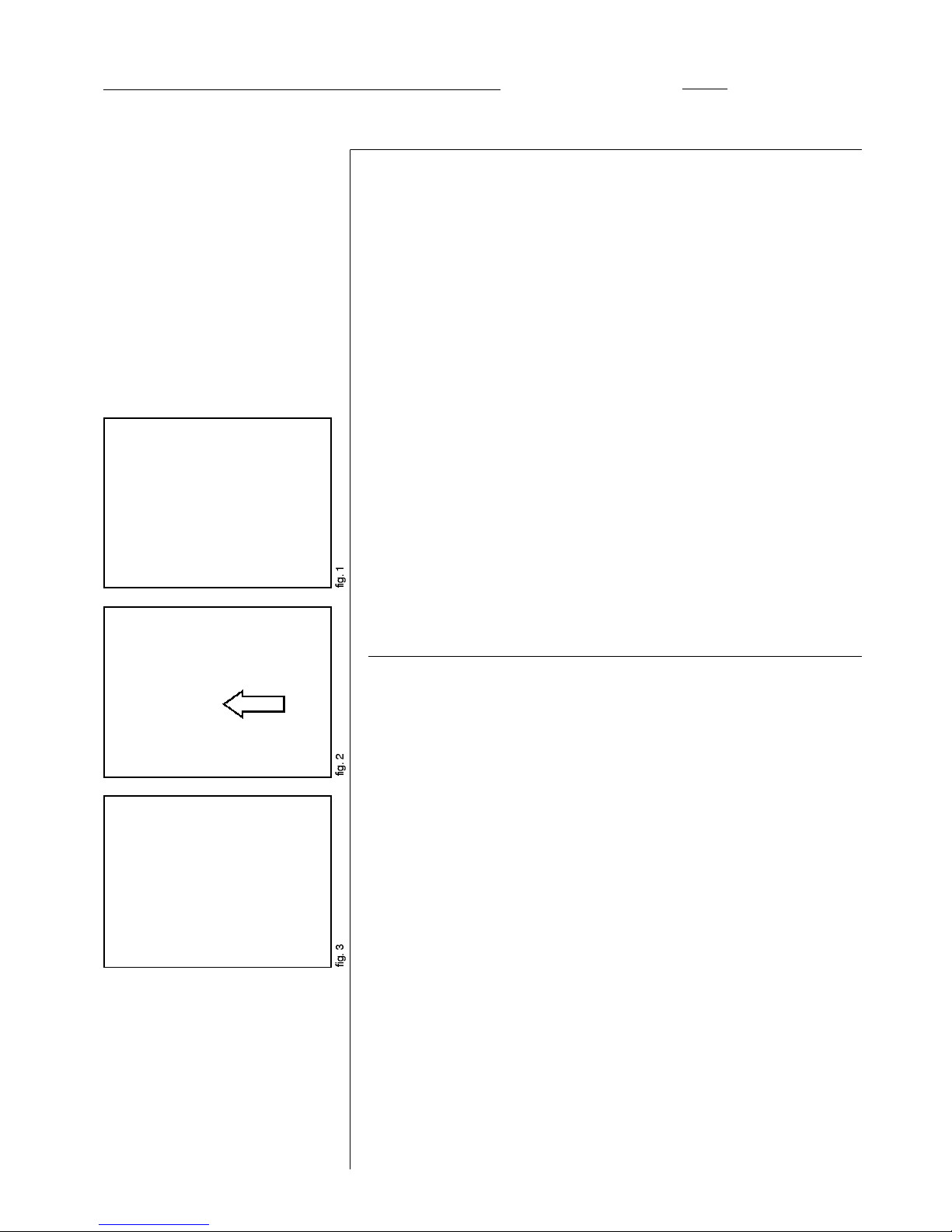
nAcceso para mantenimiento
La transmisión y filtros están ubicados debajo del habitáculo del operador (fig.1).
Para tener acceso a los mismos debemos levantarlo de la siguiente forma:
-Abrir la guantera situada a la derecha del operador debajo del apoya-brazos y
tirar del mando situado en la parte trasera de la guantera (fig.2 ) para desenclavar
el retenedor de la cabina. La cabina voltea, teniendo acceso para efectuar las
operaciones de mantenimiento.
-Una vez levantado el habitáculo, este debe fijarse mediante el tope existente en
el amortiguador de gas del lado derecho, insertando el pasador en el agujero de
fijación. Con ello evitaremos que pueda bajar y causar un accidente.
nNivel de aceite hidráulico y filtro
El nivel de aceite se debe comprobar siempre con las horquillas en la posición baja
de reposo y con el motor parado. La máquina debe situarse en un terreno horizontal.
Aflojar la varilla "1" (fig. 3) y comprobar si el aceite llega a la marca superior. Si es nece-
sario, añadir aceite por el agujero de la varilla de nivel.
El vaciado del depósito se hace por el tapón situado en la parte inferior del depósito.
En el circuito hidráulico va un filtro de aspiración, situado en el interior del depósito.
Es un filtro metálico que debe limpiarse por primera vez a las horas 50 y
posteriormente cada vez que se vacíe el depósito hidráulico (Consultar
cuadro de mantenimiento).
Nota:El depósito de aceite está equipado con un indicador de nivel bajo de
aceite. Al llegar a esta nivel se encenderá el indicador en el cuadro de mandos
eléctrico y sonará un avisador acústico. Añadir aceite inmediatamentepara no
dañar las bombas hidráulicas.
nOnly use OEM (Original Equipment Manufacturer) parts obtained from your
AUSA dealer.
nGeneral Maintenance Recommendations
The hydraulic system should be checked periodically to avoid poor performance or
accidents, which might be caused by hydraulic oil leaks or by maladjustment of the
pressure relief valves. Take precautions to avoid spilling before disconnecting any of
the fluid system circuits. Never use an open flame to check fluid leaks or levels.
nAccess for maintenance
The engine, the transmission and filters are located under the cabin floor (fig.1).
To access them, you have to procede as following:
-Open the glove compartment located under the arm rest at the right of the
operator seat.
-Pull the control located at the back side of this compartment (fig.2) to unblock
the latch of the cabin, then lift and tilt it forward.
-Lifted cabin is moved to this position by a jack cylinder on each side of the
machine. To prevent the falling down of the cabin when carry out maintenance
operations, insert the proper safety pin in the appropiate hole of the jack red
part located on the right side.
nHydraulic oil level and filter
With the forklift on level ground, the engine stopped and the forks on the lowest posi-
tion, check the hydraulic oil level by means of the dipstick (1). Top up if necessary
through this dipstick filling hole.
Into the oil tank, there is a metallic gauze filter for load functions circuit. It has to be
removed and cleaned periodically.
To drain the hydraulic oil tank removes the drain plug at the bottom rear of the tank.
See MAINTENANCE CHART for hydraulic oil specifications and for recommended
change intervals.
Operaciones
periódicas de
mantenimiento
Periodic
maintenance
operations
8
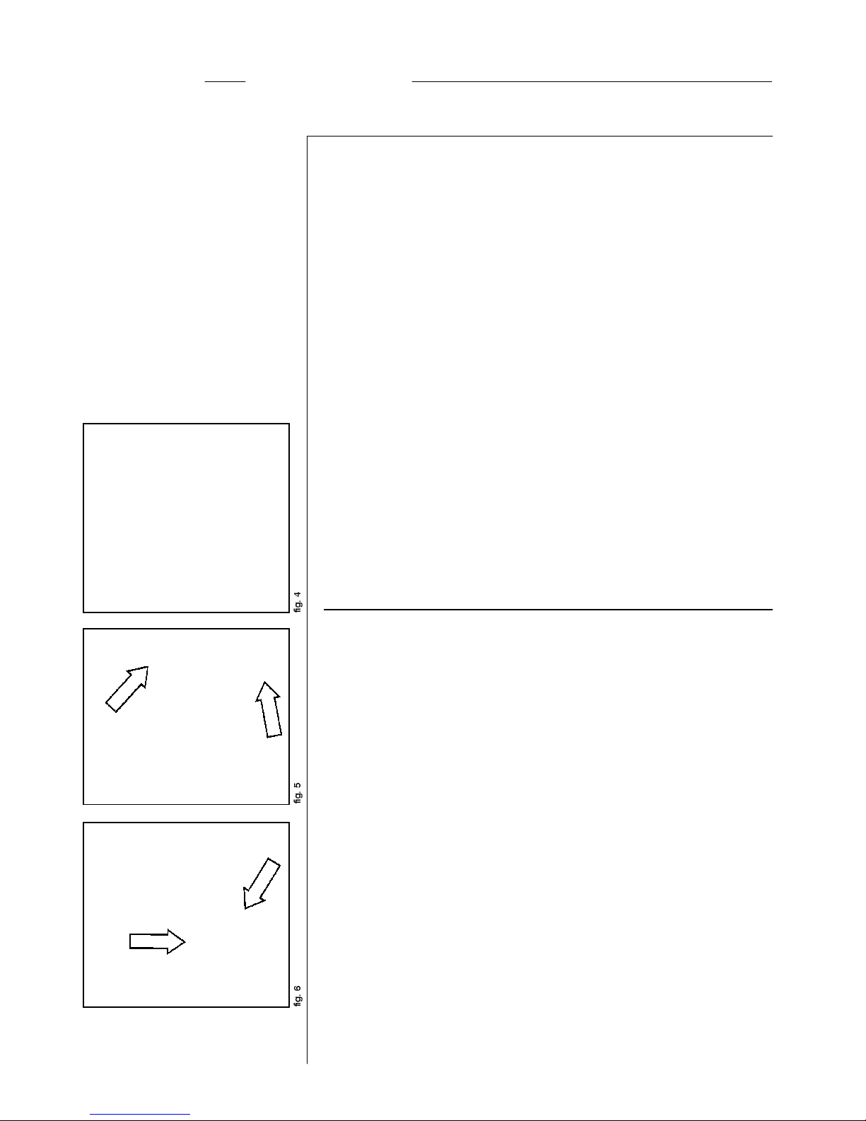
nFiltro de la transmisión hidrostática. (fig. 4)
El circuito está equipado con un filtro de cartucho que deberá sustituirse periódicamente.
(Consultar cuadro de mantenimiento).
El soporte del filtro va provisto de un indicador de obturación (vacuómetro). Con el
motor en marcha la aguja tiene que estar situada en la zona verde o como máximo en
la amarilla. Si se acerca o se sitúa en la zona roja, reemplazar el filtro de cartucho lo
antes posible.
nMovimiento de la máquina averiada.
El remolcado de la carretilla solo se aconseja en caso de avería, cuando no haya otra
alternativa, pues ello puede dañar seriamente la transmisión hidrostática. Siempre
que sea posible se recomienda efectuar la reparación en el lugar en que esté para-
da. En caso contrario el movimiento solo debe hacerse en trayectos cortos y a poca
velocidad.
Antes de remolcar, se deben de apretar a fondo los tornillos centrales de las válvulas
de presión máxima de la bomba hidrostática (fig. 5). Para ello se aflojarán las contrat-
uercas. También se debe aflojar y desenroscar las tuercas de fijación del conjunto
freno hasta el final de los espárragos y retirar el conjunto freno hasta que quede
desacoplado (fig. 6).
Una vez reparada la máquina, aflojar de nuevo los tornillos centrales de la válvulas del
grupo hidrostático y acoplar el freno.
nTuberías y latiguillos hidráulicos.
-Cuando se desmonte una tubería o latiguillo hidráulico, proteger los extremos
tapándolos para evitar que entre suciedad y posteriormente contamine el circuito.
Sustituya la tubería o latiguillo. Solo así asegurará la estanqueidad de la conexión.
-Utilice únicamente recambios originales AUSA. Sólo así garantizará que
la longitud, conexión, estanqueidad y durabilidad de las tuberías y latiguillos
de su máquina siguen conservando el mismo nivel técnico que en el momento
de la entrega.
-Cuando sustituya un latiguillo, alójelo por el lugar idóneo evitando roces y
con los radios de curvatura adecuados.
nHydrostatic oil filter. (fig. 4)
The hydrostatic oil filter is assembled outside of the tank on the hydraulic circuit, under
the floor cab.
The cartridge has to be changed periodically. There is a clogged indicator on the filter.
The arrow has to remain into the green or yellow zone. If it is into the red zone, replace
the cartridge as soon as possible.
nTowing the machine. (fig. 5)
If the machine must be towed for short distances, only do so with a solid tow-bar to pre-
vent any lateral sway. Attach the tow bar to the bolt at the rear of the counter weight. Drive
slowly and carefully at a speed not exceeding 6 mph. Comply with all state laws govern-
ing the operation / towing of an off-highway machine on public roads and highways.
Although it is not recommended to tow the machine on a long way, if you need to carry
out it, follow these instructions: Override the maximum pressure valves of the hydro-
static pump by tighten deeply the central screws (shown on fig. 5). Previously, loose
the locknuts. Remove and disengage the brake assembly. To do it, loose and unscrew
the nuts and studs fastening it. (Fig. 6)
When the machine is ready to work, assemble the brake again.
Set again the maximum pressure of the hydrostatic pump valves by loosening the cen-
tral screws and fastening the locknuts.
nHydraulic pipes
-When stripping a hydraulic pipe, cover the ends to keep dirt from entering the
pipe and polluting the circuit. Replace the pipe. This is the only way of ensuring
the connection tightness.
-Use genuine AUSA parts only. It is the only way of making sure that the length,
connection, tightness and durability of the pipes remain at the same technical
level as on delivery.
-When replacing the pipe, avoid any friction housing it through the opening with
the appropriate curvature radius.
Operaciones
periódicas de
mantenimiento
Periodic
maintenance
operations
9
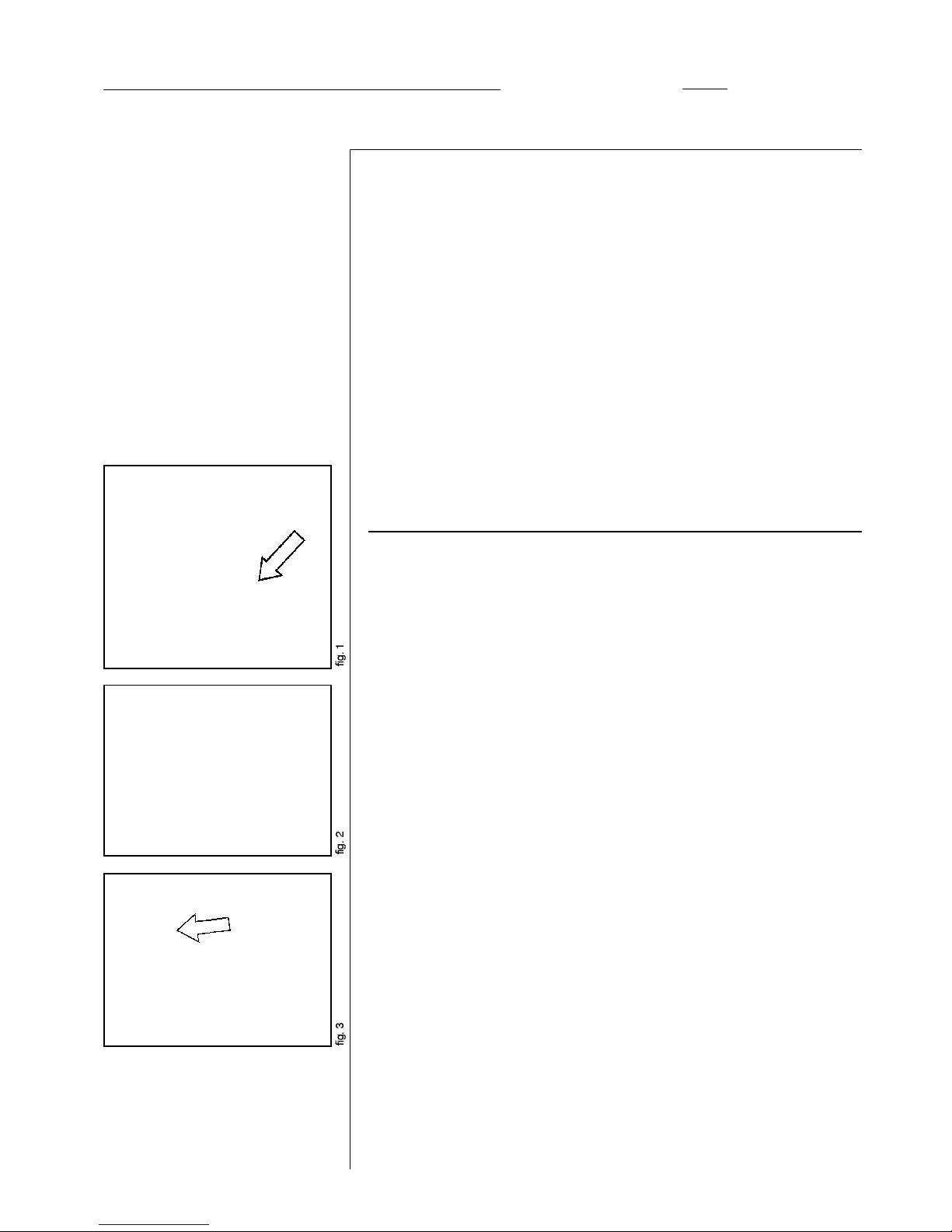
-Poner en marcha la máquina e inclinar el mástil hacia adelante (operario sentado
en la máquina, empujar el joystick hacia la derecha) hasta que llegue a la posición
mas adelantada.
-Poner el seguro en el cilindro de sujeción de la cabina (fig. 1)
-Conectar un manómetro a la toma existente en la bomba de servicios
hidráulicos (fig. 2). La escala del manómetro debe ser de 300 bar o superior.
-Cerrar la cabina y sentarse a la máquina. Accionar el joystick hacia la izquierda.
Cuando el mastil esté a la máxima inclinación y acelerando el motor a 2000
r.p.m., el manómetro nos mostrará a la presión que actúa la válvula de
seguridad del distribuidor.
nSi la presión no es la correcta, graduar de la siguiente manera:
-Localizar el distribuidor "1" (fig. 3)
-Aflojar la contratuerca y girar el tornillo Allen en el sentido de las agujas del reloj
para incrementar la presión hidráulica y al revés para reducirla. "2" (fig.4).
nPresiones de trabajo
CH - 200 y CH - 200 x 4: 180 bar
CH - 250 y CH - 250 x 4: 220 bar
-Start the machine and cant the mast forward to the top (worker sitting on the
machine, push the joystick to the right).
-Fit the safety pin on the prop jack to keep the cabin up (Fig. 1).
-Connect the pressure gauge on the nipple of the hydraulic equipment pump (Fig. 2).
The range of the pressure gauge has to include the range of 300 bar (4350 psi)
or more.
-Sit down on the operators seat and close the cabin. Pull the joystick to the left.
-Act the tilting cylinders forward or backward to the end of their stroke, with Diesel
engine at 2000 rpm approximately, the gauge pressure registers the relief pressure
of the safety valve.
nShould the pressure be inappropriate, gage as follows:
-Find the slide-valve located underneath the motor lid (cabin).
-Remove the sealing and unscrew the metal lid as shown on figure.
Slack the back nut and turn the Allen screw clockwise to increase the hydraulic
pressure (to decrease the pressure, turn the Allen screw anti-clockwise).
nWorking pressure
CH 200 y 200 x 4: 180 bar (2610 psi)
CH 250 y 250 x 4: 220 bar (3190 psi)
Regulación
de la válvula
de seguridad
del distribuidor
Setting the
safety valve of
the distributor

10
-Conectar un manómetro en la toma existente en la bomba de la dirección
hidráulica. La escala del manómetro ha de ser de 200 bar o superior (fig. 1).
-Una vez conectado el manómetro, accelerar el motor a 2000 rpm. y girar el
volante hacia cualquier de los dos lados hasta que la dirección haga tope. De
esta manera el manómetro nos indicará la presión a la que actúa la válvula de
seguridad de la dirección hidráulica.
nSi la presión no es la correcta, graduar de la siguiente manera:
-Quitar la alfombra de la chapa piso cabina.
-Aflojar las cuatro tuercas de sujección de la columna de dirección.
-Aflojar las tuercas de sujección del Orbitrol. Apartar la columna hacia un lado
para acceder al tapón regulación Orbitrol.
-Sacar el tapón (1) desenroscando y girar con un destornillador el tornillo interior
en el sentido de las agujas del reloj para incrementar la presión hidráulica y al
revés para reducirla.
nPresiones de trabajo
CH - 200 y CH - 200 x 4: 160 bar.
CH - 250 y CH - 250 x 4: 160 bar.
-Join up the manometer to the hydraulic steering in the pressure intake located in
the pump. The scale of the manometer must read over 200 bar (2900 psi) (fig. 1).
-After connecting the gauge pressure on the steering control, with the engine set
at 2000 rpm approximately, turn he steering wheel fully clockwise (or counter
clockwise), to the end of its stroke. The gauge pressure registers the relief pressure
of the steering safety valve.
nShould the pressure be inappropriate, gage as follows:
-Remove the carpet from the floor plate (cabin).
-Loose the 4 nuts fastening the steering column.
-Loose the nuts fastening the steering control (Orbitrol). Put the steering column on
a side to have good access to the cap for setting the relief safety valve.
-Unscrew the lid (1) and use a screwdriver to turn the inside screw clockwise to
increase the hydraulic pressure (to decrease the pressure, turn the inside screw
anti-clockwise).
nWorking pressure
CH - 200 y CH - 200 x 4: 160 bar. (2320 psi)
CH - 250 y CH - 250 x 4: 160 bar. (2320 psi)
Regulación
de la válvula
de seguridad
de la dirección
hidráulica
Setting the
safety valve of
the hydraulic
steering

Ma y Mb
G
R
SAspiración
Presión de
carcasa
Presión de
pilotaje
Presión de
alimentación
Presión de trabajo 600 bar
40 bar
40 bar
10 bar
M12x1'5
M12x1'5
12x1'5
33x2
20 - 25 bar
20 bar
4 bar (max.)
nPara comprobar el funcionamiento correcto del sistema hidrostático, la bomba
tiene varias tomas para comprobar las presiones. El siguiente esquema muestra
dónde localizar las tomas para conectar los manómetros y la rosca de las mismas.
Consulte este esquema cuando instale los manómetros.
11
DENOMINACIÓN
TOMA DE
PRESIÓN
PRESIÓN
A MEDIRMANÓMETRO
RECOMENDADOROSCAPRESIÓN
X1 y X2
(SOLO EN CH- 250)
M12x1'5 (CH-200)
M18x150 (CH-250)
320 bar (CH-200)
415 bar (CH-250)
Tomas
de presión
y manómetros
grupo hidrostático
Pressure
intakes and
manometer of the
hydrostatic group
nThe pump has several intakes to check the correct pressure and running of the
hydrostatic system. The following diagram shows where to find the intakes and
threads where to join up the manometers. Always check the diagram when joining a
manometer.
Ma and Mb
G
R
SCharge Pump
Inlet Vacuum
Case
Pressure
Servo
Pressure
Charge
Pressure
Working PressureM12x1'5
M12x1'5
12x1'5
33x2
GAUGE
PORT NAMEPRESSURE
MEASUREDRECOMMENDED
GAUGE SIZEFITTING
PRESSURE
X1 and X2
(CH-250)
M12x1'5 (CH-200)
M18x150 (CH-250)
320 bar
(4640 psi)
415 bar
(617,5 psi)
10 bar
(145 psi)
40 bar
(580 psi)
40 bar
(580 psi)
600 bar
(8700 psi)
4 bar
(58 psi max.)
20 bar
(290 psi)
20 - 25 bar
(290-362 psi)
CH-200
CH-250

12
-Conectar un manómetro en la toma G, tal y como muestra la imagen.
-Una vez conectado el manómetro, poner en marcha la máquina, y nos indicará
a la presión de alimentación de la bomba que debe estar entre 20-25 bares.
-Join up a manometer to the G intake, as shown on figure.
-After joining the manometer, start the machine in order to read the
pump's charge pressure, which should be between 20 and 25 bars.
Presión de
alimentación
del grupo
hidrostático
Charge
pressure of
the hydrostatic
group

13
-Conectar un manómetro en las toma Mb (máquina en marcha hacia atrás)(fig 1).
-Una vez conectado el manómetro, poner en marcha la máquina y leeremos
la presión a la que está trabajando el circuito hidrostático hacia atrás. Si
situamos la máquina en una fuerte rampa y la frenamos acelerando a
fondo, el manómetro nos indicará la presión máxima de trabajo de la
bomba que debe ser: (fig. 2)
- CH-200320 bar
- CH-250415 bar .
-Cambiar la toma de presión de Mb a Ma (máquina en marcha hacia adelante)
-Una vez conectado el manómetro, poner en marcha la máquina y leeremos la
presión a la que está trabajando el circuito hidrostático hacia adelante. Si
situamos la máquina en una fuerte rampa, en velocidad larga en caso de la
CH-200, y la frenamos acelerando a fondo, el manómetro nos indicará la
presión máxima de trabajo de la bomba que debe ser:
- CH-200320 bar
- CH-250415 bar
-Join up a manometer to the intake numbered Mb (machine running back)(fig 1).
-After joining the manometer, start the machine and read the working pressure
of the hydrostatic group for backward motion. If we place the machine on a steep
ramp and brake it by boosting it to the top, the manometer will read the pump's
maximum working pressure,(fig. 2) which should be of:
- CH-200320 bar (4640 psi)
- CH-250415 bar(617,5 psi)
-Join up a manometer to the intake numbered Ma (machine running front)(fig 1).
-After joining the manometer, start the machine and read the working pressure
of the hydrostatic group for forward motion. If we place the machine on a steep
ramp and brake it by boosting it to the top, the manometer will read the pump's
maximum working pressure,(fig. 2) which should be of:
- CH-200320 bar (4640 psi)
- CH-250415 bar(617,5 psi)
Presión
de trabajo
del grupo
hidrostático
Working
pressure of
the hydrostatic
group

API CE/SF
ISO
6743/4 HM
TOTAL
TOTAL
Cuadro de
Mantenimiento
Maintenance
chart
14
nVerificar el nivel de aceite todos los días. No olvidar las renovaciones de aceites
y sus filtros.
nLa calidad del aceite para cada órgano tiene una importancia capital para su
buen funcionamiento.
OrganosCalidades recomendadasEspecif.Periodicidad
de renovación
Circuito
hidráulico
REPSOL
TELEX
CEPSA
HM-46
OIL 46
MOBIL
DTE-26
HPL 46
SHELL
TELLUS
DIN 51524
BP
ENERGOL
Aceite y filtros.
1ª renovación y
limpieza a las 50 h.
Siguientes cada
1000 horas.
VG-46Temperaturas ambiente habitualmente inferiores a 10ºC.
VG-68Temperaturas ambiente habitualmente entre 10ºC y 40ºC.
VG-100Temperaturas ambiente habitualmente superiores a 40ºC.
API CE/SF
ISO
6743/4 HM
TOTAL
TOTAL
nCheck hydraulic oils level every day. Change oil and filters at frequency
recommended below.
nQuality oil is essential for good performance.
Descriptions
Recommended qualitySpeci.Change
frequency
Hidráulic
Circuit
REPSOL
TELEX
CEPSA
HM-46
OIL 46
MOBIL
DTE-26
HPL 46
SHELL
TELLUS
DIN 51524
BP
ENERGOL
Oil and filter.
First after 50 h.
Next every 1000 h.

Other manuals for CH 200
1
This manual suits for next models
3
Table of contents
Other AUSA Forklift manuals


