AUSA CH 200 User manual

CH 200
CH 200 x4
CH 250
CH 250 x4
OPERATOR’S
MANUAL
ENGLISH

AUSA Forklift
CH 200
CH 200 4x4
CH 250
CH 250 4x4


3
CH 200 / CH 250
Foreword
Thank you for choosing this AUSA Models CH200/CH250 Forklift. The purpose of this
Operators Manual is to provide you, the user, with instructions concerning the productive, safe
and efficient use of this forklift. You should read and understand this manual before operating the
forklift. The Manual contains safety messages concerning the use of the forklift. Remember that
“you” are the key to safety.
The Manual also contains instructions for some adjustments and for maintenance of this fork-
lift. Follow these instructions carefully while performing routine maintenance checks and keep a
record of all maintenance. As wide variations in operating conditions may be experienced, you
are urged to contact your AUSA Distributor to resolve any operational or service problems.
Please have all operators of this forklift read and understand this Manual.
When not in use keep it stored on the forklift in the Manual holder box under the arm rest.
This forklift is designed and intended for off highway use. If it is temporarily operated on any
public street or highway, the state and local laws governing speed, size, weight, brakes and ligh-
ting must be complied with.
For further information you may write, FAX or E-mail to:
AUSA Center, S.L.U.
Apartado P.O.B. 194
08243 MANRESA (Barcelona) SPAIN
Tel. 34 - 93 874 75 52 / 93 874 73 11
Fax 34 - 93 873 61 39 / 93 874 12 11 / 93 874 12 55
E-mail: [email protected]
Web: http://www.ausa.com
AUSA is continuously trying to improve the efficiency, productivity and safety of its products
and reserves the right to make such improvements without incurring any obligation to make
changes to forklifts previously sold.
Because of this policy of striving for constant product improvement, the specifications and
operating instructions shown in this Manual may be different from prior forklift models.
M O P 0 21 2 0 2 0 3

5
CH 200 / CH 250
Index
6
Identification of the forklift components
7
Vehicle identification and serial numbers
8
15
Controls and instruments
16
Instrument panel and controls (components)
17
Instrument panel and controls (multifunction instrument)
18
Operating the machine
27
Parking the machine
30
Periodic maintenance operations
35
Capacities
36
Greasing points
50
Maintenance chart
Technical characteristics
11
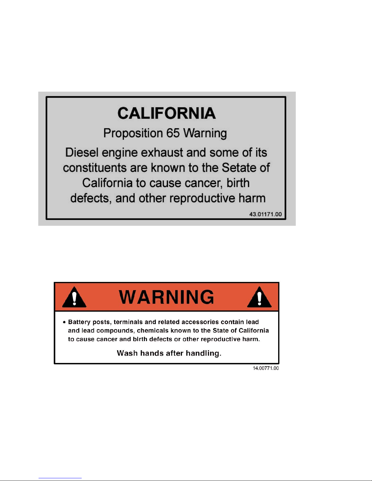
Machine decals USA market
22
Safety
13
Machine decals UK market
28
Transporting the machine
37
Electric circuit CH 200
42
Electric circuit CH 250
47
Hydraulic diagram (Side-shift)
48
Hydraulic diagram (Hydromatik) CH 200
49
Hydraulic diagram (Hydromatik) CH 250

6
CH 200 / CH 250
Identification
of the forklift
components
Term such as right, left, front and rear when used in this Operators Manual indicate the right
and left sides of the machine, the front and back of the machine, as viewed from the operators
seat looking forward.
Identification components
1- Overhead guard.
2- Driving and load control.(Joystick)
3- Parking brake switch.
4- Driver seat with seat belt.
5- Diesel tank.
6- Hydraulic tank.
7- Forks.
8- Lifting mast.
9- Rotating beacon.
10- Lighting equipment (in option).
11- Rear-view mirror.
5
2
8
4
7
6
9
1
10
3
10
11

7
CH 200 / CH 250
Vehicle
Identification
and Serial
Numbers
Important! Writes your machine Model number, date of sale, chassis and engine serial num-
ber in the spaces provided below. Give this information to your AUSA dealer when you need parts
or information for your machine. Make a record of these numbers in your files.
Model number: ....................................................................................
Date of sale: ........................................................................................
Chassis serial number: .......................................................................
Engine serial number: ..........................................................................
The Vehicle Identification Plate is located at the left of the operators seat (fig. 1). The
Engine Serial Number is located on the left side of the engine (fig. 3-4). The Chassis Serial
Number is located on the right side of the chassis (fig. 2).
Principals components of identification plates
The plates of every components not built directly by AUSA, (for example: engines, pumps, etc.)
are directly applied on the same components, in points where the respectives makers put them
originally.
(fig. 4 - KUBOTA V2003T) (fig. 1)(fig. 2)
(fig. 3 - ISUZU 4LE2)

8
CH 200 / CH 250
Technical
characteristics
Diesel engine
Four cylinders, four stroke, water-cooled. Electrical starter. Mixed radiator (water/oil).
CH 200: Isuzu 4LE2 - Tier II - Power 51HP (37.5 Kw in accordance with DIN 70020) or 46 HP
(34.5 kw at 2,700 rpm in accordance with DIN 6270B).
CH 250: KUBOTA V2003T - Power 62.9 HP (46.3kw in accordance with DIN 70020) or 42.6 HP
(42.6kw at 2,700 rpm in accordance with DIN 6270B).
See the engine instructions handbook.
Transmission
Hydrostatic system with variable flow pump.
Both models with 2 wheel drive version (2WD) and 4 wheel drive version (4WD).
CH 200: Hydrostatic motor of two speeds selected by electrical switch. 4,713 PSI(325 bar).
CH 250: Hydrostatic motor of variable flow. 6,091 PSI (420 bar)
Directional control
Forward / Backward direction selected by an electric switch underneath of the joystick. When a
direction is selected, the arrow lamp indicator light on.
Steering
Hydraulic powered with one double acting hydraulic cylinder on the rear axle.
Working pressure: 2320 PSI (160 bar).
Service Pressures:
CH 200Compact :
Front. 10.0/75-15.3; 96 PSI (6,5 bar). Rear. 6.50-10; 65 PSI (4,5 bar).
CH 200 :
Front. 11.5/80-15.3; 65 PSI (4,5 bar). Rear. 7.00-12; 123 PSI (8,5 bar).
CH 200x4 :
Front. 11.5/80-15.3; 65 PSI (4,5 bar). Rear. 27x10-12; 123 PSI (8,5 bar).
CH 250 :
Front. 12.5/80-18; 65 PSI (4,5 bar). Rear. 7.00-12; 123 PSI (8,5 bar).
CH 250x4 :
Front. 12.5/80-18; 65 PSI (4,5 bar). Rear. 10.0/75-15.3; 51 PSI (3,5 bar).
Brakes
Service brake. Multidisc sealed hydraulic brake.
Parking brake. Multidisc sealed brake spring applied, hydraulically released.
Hydraulic circuit
One double gear pump for steering system and load function system driven by hydrostatic
pump. Two spool valve block. Maximum load lowering speed controlled by check valve.
Service pressure:
CH 200: 2610 PSI (180 bar).
CH 250: 3190 PSI (220 bar).
Hydraulic tank capacity: 12.4 US gal or 10.34 UK gal (47 liters).

9
CH 200 / CH 250
Technical
characteristics
Working temperature
From -15ºC to 40ºC.
Electrical equipment
Electrical starter 1,8 Kw (CH 200) and 1,4 Kw (CH 250). Pre-heating spark plugs. Alternator of
20A and regulator. Battery 12V - 70 AH. Horn. Rotating beacon. Back-up alarm. Engine oil level
alarm. Hydraulic oil level alarm. Coolant temperature alarm.
Weight (with full tanks)
CH 200 : 3800 kg (8,377lbs). CH 200x4 : 3900 kg (8,598lbs).
CH 250 : 4200 kg (9,259lbs). CH 250x4 : 4300 kg. (9,479lbs).
(The Compact machine has the same weight).
Load Capacity
With the load center of the load at 500 mm. (see load charts)
CH 200: 2.000 Kg; CH 250: 2.500 Kg.
With the load center at 24 inches (600 mm)
CH 200: 4040 lbs (1835 Kg).
CH 250: 5060 lbs (2294 Kg).
Fork carriage
Class: FEM/ISO 2.
Standard mast
Lifting height : 10ft. 10in. (3,30 m).
Free litf: 6 inches (150 mm).
Forks length: 47 inches (1200 mm).
Lifting speed
Without load: 103 ft/min (0,526 m./seg). with load: 101 ft/min (0,513 m./seg).
Lowering speed
Without load: 81 ft/min. (0,412 m./seg). With load: 125 ft/min (0,637 m./seg).
Control panel
The controls are integrated in the steering column.
Lighting (in option)
Work lighting equippment, steering indicators, parking lights and warning.
Overhead guard
Manufactured according with ISO 6055.
Other equipment
Side-shift carriage (st).
Aisle widths
See graph.

10
CH 200 / CH 250
Technical
characteristics
Optional equipment
*4 Wheel driving transmission *Standard lateral displacement.
continuously engaged (compen system) *Super-elastic solid tyres.
*Partially closed cab (front and rear windshield). *Extra wide tyres.
*Closed cab with heating. *Lighting equipment.
*Hydraulic shovels: 10.5 cu.ft and 14 cu.ft
*Other masts and attachments are also available in option.
*Load backrest (standard for USA market).
*Electronic equipment anti-theft.
*Front laminate windshield with wiper.
*Oxi-catalytic exhaust purifier.
*Rear windshield with wiper.
*Filter of gas-oil with water separator

11
CH 200 / CH 250
Machine
decals
(USA market)
Information

12
CH 200 / CH 250
Machine
decals
(USA market)
Warning
Load charts

13
CH 200 / CH 250
Machine
decals
(UK market)
Information

14
CH 200 / CH 250
Load graphs
Machine
decals
(UK market)

15
CH 200 / CH 250
Controls and
instruments
Pedals (fig. 1)
1 - Inching pedal for slow approach and emergency brake at the end of the path
Depressing the pedal, the machine stops being able to accelerate the engine for working
appliances. Loosing it slowly the machine will begin to move.
2- Brake pedal
3- Accelerator pedal
Brake and accelerator pedals above serve the same function as they do in a car.
Back-up alarm
Its sounds when the machine goes backwards.
Joystick (fig. 2 and 3)
The joystick controls the forward or backward travel direction of the forklift as well as controls
the movements of the mast and forks. It is the right side of the driver’s seat.
Forward and backward direction control (fig.2)
By means of an electrical switch (1) located on the joystick at the right of the operator seat.
When the lights of the arrows are off, the control switch is in neutral. Pushing the switch forward,
the machine drives forward and pushing the switch backwards, the machine drives backwards.
In each case the corresponding arrow will be lit.
Note. When the parking brake is engaged and the operator is not sitting on the seat the arrows
light are also off and directional control is disconnected.
Horn (fig.3)
The horn is activated by the button located on the left of the joystick (5).
Speed control (fig.3) Only in CH 200 and CH 200 x4
Pushing the joystick switch button (4) the fast speed is connected/disconnected. When it is
connected the fast speed lamp on the instrument panel is lit.
Emergency control brake
In emergency event, use the inching pedal.
Parking brake (fig.4)
The parking control works electrically by means of the switch (1).
Load controls (fig.2)
The joystick to control the load movements is located at the
right of the driver.
·Up and down control. Pulling the joystick to backwards
will raise the forks upward and pushing to forward will lower the
forks downward.
·Tilt control. Pushing the joystick to the right will tilt the mast
and the front of the forks forwards. Pulling the joystick on the
left (to driver) will tilt the mast and front of the forks backwards.
·Side shift control (option). Pushing the joystick switch
button (2) and pulling the joystick to the left (operator) will move
the forks to the left and pushing the joystick to the right will
move the forks to the right. Always center the carriage when in
transit or when transporting a load.
· 4th hydraulic control for attachments (option). Pushing
the joystick switch button (6) and pulling the joystick forwards
and backwards, the auxiliar hydraulic circuit (4th valve) is on
and hydraulic pressure is supplied to the quick hydraulic cou-
plings located on the left side of the mast.
(fig. 2) (fig. 1)(fig. 4)
12
3
(fig. 3)
4
1
5
6
1
2

16
CH 200 / CH 250
Components
1 - Multifunction Instrument (see next page)
2 - Rotating beacon switch. To switch on, push the button, it will light, to switch off push the
button again.
3 - Parking brake switch. When the parking brake is applied, the button lits.
4 -Lighting switch (version with lighting equipment). This switch has two positions, the first
connect the parking lights and the second connects the low beams.
5 - Working lamp switch (version with lighting equipment). This switch connects the wor-
king lamp if it is assembled.
6 - Hazard warning switch (only in forklift with lights). This switch connects the warning
lights on the four corners of the forklift.
7 - Heating fan switch (version with closed cabin). The heating fan has two speeds which
are regulated by this switch.
8 - Fuse box. The fuse box has places for 11 fuses. See the Electrical Diagram at the rear of this
Manual to identify the number and function of each fuse.
9 - Switch lever for turn signal, high beam, windshield wiper and water pump (version
with lighting equipment or windshield)(fig.3)
9.1 Turn signal switch. Push the lever to the right or to the left according to the side
chosen for turning.
9.2 High beam switch. Push the lever upward to switch on the high beams. When
connected high beam lamp on the dashboard is lit.
9.3 Windshield wiper switch. Turn the lever to switch on the windshield wipers.
9.4 Windshield water pump switch. Push this button at the end of the lever, to
switch on the water pump.
10 - Starter switch. See clause “starting the engine”.
11 - Anti-theft system of security (optional). it is activated or disabled by means of the record
located in the key ring (1) confronting it to the sensor (2). (fig.4)
12 - This pushbutton does not have any function.
(fig. 1)
(fig. 3)
4
1
2
3
10
(fig. 2 - STARTING KEY DETAIL)
9
1
2
(fig. 4)
Instrument
Panel
and controls
(See fig. 2)
1
2
4 5 6 3
8
(fig. 1)
8
12

17
CH 200 / CH 250
Instrument
Panel
and controls
Multifunction instrument
A - Hourmeter. This gauge indicates the total running time of the forklift engine to enable ser-
vicing of the engine at proper intervals. (See Maintenance Chart for servicing frequency).
B - Fuel level. This gauge indicates the diesel fuel level.
C - Fuel lamp. When the diesel fuel level is at the minimum level this alarm is lit.
D - Air filter lamp. When the air filter of the diesel engine becomes clogged with dirt, this
lamp will light. The air filter should be immediately cleaned or serviced.
E - Engine pre-heat lamp. When this lamp glows it indicates that the engine pre-heat plugs
are in operation and heating the combustion chamber to a temperature that will enable firing of
the vaporised diesel fuel.
F - Hydraulic oil lamp. When the hydraulic oil level is at minimum level this lamp is lit.
G - Oil pressure lamp. When this lamp is lit it means that the engine oil level is low
causing low oil pressure to the engine. The engine should be stopped immediately to pre-
vent engine damage. Add oil to the engine until the proper level is reached.
H - Charge battery lamp. This gauge shows the condition of the battery and will tell you if
the battery charge is too low or if the alternator is not charging properly. Once the engine starts
to run, this red lamp will go out: If it remains lit, stop the engine and determine the cause.
J - Engine temperature lamp. This gauge shows the temperature of the coolant in the engine
cooling system. When this lamp glows it means that the engine is operating at high temperatu-
re which could damage the engine. The engine should be stopped immediately to determine
the cause of the high temperature. It could be low coolant, debris in the radiator or a thermos-
tat, which does not operate correctly.
K - Fast speed lamp (only CH200 and CH200 x4 wheel driving). This lamp is lit when the
faster speed is selected.
L - High beam lamp (with lighting equipment). This lamp is lit when high beams are selec-
ted.
M - Turn signal lamp (with lighting equipment). This lamp will blink indicating turn signals
are operating.
(fig. 2)
1

18
CH 200 / CH 250
Operating
the machine
Come in and come out of the forklift
Don't hold and pull of the steering wheel to come in/off the forklift, use the handles located on
the overhead guard and always support your foot on the rough bands of the step, to prevent any
downfall when you come in or come out.
Adjusting the seat and the steering wheel (figs. 1-2-3-4-5)
Before starting work with the forklift each day adjust the seat for the most comfortable position.
To move the seat backwards and forwards reach under the right side of the seat and locate a
small lever (1). Turn the lever and move the seat to the desired position. According to the weight
of the driver, set the seat with the lever (2). Normally it is adjusted for a driver weighting 198 lb.
To adjust the tilting backrest of the seat to your confort turn on the knob(3) (fig.4).
Securely fasten the seat belt.
To adjust the steering wheel in a comfortable position, loose this lever (5) move the column ade-
quatelly and tight it again.
Starting the engine
For safety reasons, when starting the engine the driver should be sitting on his seat, directional
control switch in neutral and the parking brake engaged.
Insert the key in the ignition switch, turn it fully clockwise and depress lightly the accelerator
pedal. At this moment the pilots of battery charge, oil pressure and pre-heat in the dashboard
panel will illuminate.
After some seconds, the pre-heat light will go off and the engine will start. When engine is run-
ning, battery charge and oil pressure lights will go out.
If the engine fails to start, repeat all above steps. Allow 30 seconds between attempts.
Important! With cold weather, before driving the machine, have the engine running some minu-
tes to improve oil circulation and lubrication.
WARNING
Before each period of operation, check the forklift for correct operation of
the steering, brakes, hydraulic controls, instruments and safety equip-
ment. Check the neutral position of directional control lever. A machine
that runs correctly is more efficient and can prevent accidents. Make all
necessary adjustments or repairs before you operate the machine.
(fig. 5)
(fig. 2)
(fig. 3)
1
2
(fig. 1)
1
2
(fig. 4)
3
3
ATTENTION
With ambient temperatures lower than 0ºC, AUSA recommends to run the
engine at idle speed for 3 minutes before starting to work with the forklift
in order to reach the appropiate fluency on the engine and hydraulic oil

19
CH 200 / CH 250
Operating
the machine
Jump starting the machine
Starting the machine by means of a booster battery can be done by using other 12-volt batteries,
which may then be connected to the starter motor. lf using another machine for this purpose
make certain the two machines do not touch.
1- Apply the parking brake and lower the forks to the ground.
2- Lift the cabin.
3- Make certain that the direction switch is in the neutral position.
4- Connect the positive (+) cable of the booster batteries to, the positive (+) terminal of the
machine battery. Then connect the negative (-) cable of the booster batteries to a good ground
connection on the frame of the machine.
5- Start the forklift engine in the normal fashion.
6- Disconnect the booster cables in the same order - first disconnect the booster cables from the
positive (+) terminal of the forklift battery and then disconnect the booster cables from the nega-
tive (-) terminal of the forklift battery.
When the machine is warm and idling do the following:
- Check all the instruments on the instrument panel.
- Test steering, both right and left, while moving slowly
- Raise the forks about 6in (150 mm) above the ground.
- Test the parking brake.
- Test the foot brakes for correct firmness of operation.
Understanding the Rated Capacity of the CH 200 and CH 250 forklifts
The Rated Capacity of this forklift is the weight the machine is capable of lifting under safe ope-
rating conditions. The lifting capacity of a forklift is determined by the height and weight limits
of the load. Poor ground conditions as well as shape of the load may reduce the weight that
can be safely lifted. Overloading the forks can make the forklift unstable, hard to handle, and
may be in danger of tipping over.
Inspect the load you intend to lift and make certain it is within the limits of the Load Capacity
Chart located on the left mudguard.
With load centre at 20 in or 500mm (European and ISO standards), the CH 200 has a rated
capacity of 4,384lbs or 2000Kg and the CH 250 has a rated capacity of 5,48lbs or 2,500Kg.
With load centre at 24 in or 600 mm (American Standard) the CH200 has a rated capacity of
4040lbs (1835 Kg) and the CH 250 has a rated capacity of 5060 lbs (2294 Kg)
If the load is too heavy split it and re-stack it. Use of attachments other than the two standard
pallet forks that came with this machine may reduce lifting capacity and affect other machine
handling characteristics.
If this forklift has a side-shift carriage, the capacity of the load is decreased. Reproduced below
are copies of the Load Capacity Chart for a forklift with a side-shift carriage. Study the Load
Capacity Chart for your machine carefully and make certain you understand it before lifting loads
on the forks.
Load Center (fig.1-2)
To rate the lifting capacity of forklifts manufacturers have standardized on a certain size of load.
The rated capacity of this forklift is based on a cube measuring 39in (1000mm) in accordance at
European and ISO standards, or 48in in accordance with American standards, in all three dimen-
sions with the center of gravity in the center of this cube. This is known as a 19.5 or 24in load
center (with the center of gravity 19.5 or 24in from both the vertical face of the mast and from the
lifting surface of the forks). lt is important to keep load center in mind for as the load center incre-
ases, the lifting capacity of the forklift decreases.
The relationship between the forklift and the load is altered by changes in:
*Removable attachments (see load limit charts).
*Height of the forks.
*Changes in the motion of the machine and the grade of the ground on which it is moving.
*Smoothness and stability of the ground.
*Machine stability must be maintained while these factors change constantly during forklift ope-
ration. This requires careful judgement on the part of the operator.
1- Fork Face
2- Load Center
48 in.
48 in.
48 in.
24 in. load center
(fig. 1)
(fig. 2)

20
CH 200 / CH 250
Operating
the machine
Lifting Capacity
Machine stability is maintained only when the forklift handles loads within its rated lifting capacity
and the various conditions listed above. The lifting capacity of the machine is determined by the
safe height and weight limits of the load. An overload on the forks makes the forklift unstable,
hard to handle, and will present the danger of tipping oven
Load charts
The charts you can see in (figs. 1-2) shows how much your forklift can lift as the load centre incre-
ases out to 4 in. (100 mm). Note how the lift capacity decreases as the load centre increases.
This chart is reproduced as a machine decal and is located on the mudguard in front of the dri-
ver seat for ease of reference during machine operation (fig. 3).
The chart represents the load that can be lifted on a level surface, with the load evenly displaced
(like a square box with the weight centred), and a lift height (standard mast) of 10ft. 10in. (3,3 m.)
The horizontal axis “T" (often referred to as the X axis), represents the distance in inches (mm)
that the load centre is moved forward from the face of the forks.
The vertical axis "G" (often referred to as the Y axis), shows the load weight in pounds (kgs).
The raising and lowering of the load
Must be done with the mast in its vertical or tilted-back position. Using the machine with a raised
load tilted forward should only be done when unloading. The mast inclination is a useful feature
when handling a load, but it affects both lateral and longitudinal stability. It is recommended that
when operating with a high positioned load, you do not tilt the mast past the vertical position
more than strictly necessary.
The forklift is liable to roll forward when carrying a high positioned load with the mast forward of
the vertical point, if accelerating or braking abruptly.
(fig. 1) - U.K. (fig. 2) - U..K.
(fig. 1) - U.S..A
(fig. 1) - U.S.A
Other manuals for CH 200
1
This manual suits for next models
3
Table of contents
Other AUSA Forklift manuals