Austin Kontore Crestview Chicken Coop User manual

© 2009 Austin Kontore LLC Page 1 of 54
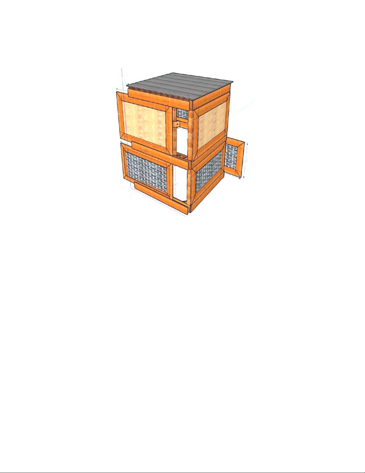
Chicken Coop Kit
The Crestview
Asse bly Guide
Version 20091011H
Austin Kontore LLC
Austin, TX
kontore.net
512-436-0512

© 2009 Austin Kontore LLC Page 2 of 54
Introduction
Thank you for purchasing our Crestview Chicken Coop kit. We are sure it will give you years of
enjoy ent.
Technical Support
If you have any questions during asse bly, please give us a call at 512-436-0512 or send an e- ail with
your question to [email protected].
Special Symbols
Repeat
The preceding step, or series of steps, will need to be repeated. This is often
the case when ore than one Door or Fixed Panel needs to be built, with each
ite being built in an identical anner.
I portant
An i portant note, which should be read before perfor ing a step, or series
of steps. Used to avoid potential asse bly proble s.
Goal More infor ation on what you are trying to acco plish during a given step.
Note An infor ational note, used to further explain the reasoning behind a step.
Assembly Overview
1. Build Panel Units (fixed panels and panel door). There are three of these.
2. Build Screen Units (fixed screens and screen doors). There are five of these.
3. Asse ble the Core Structure, ade of prefabricated squares and posts.
4. Mount Door Slide Rails. There are five of these.
5. Mount Inside Rails. A set of two.
6. Install pre-fabricated Roof.
7. Install final Fixed Screen Unit.
8. Test Door action.
9. Install Extras, like the Roost and Nesting Box slats.
10. Sand and Stain the co pleted coop.

© 2009 Austin Kontore LLC Page 3 of 54
Required Tools
Electric or hand drill. A cordless power drill is preferred, but any kind
will work.
1/8” drill bit, for wood.
Power screw driver with Phillips bit or Phillips screw driver. A power
driver will ake asse bly uch easier.
Post level (highly reco ended). Makes align ent of posts
(uprights) uch easier, since it uses bubbles in the key directions.
“Wraps around” the post and is held with a rubber band.
S all 6” to 18” level, though any level up to 28” will work.
Staple Gun. Either anual or electric, but electric will ake screen
asse bly easier.
Cla ps. One-handed bar cla ps (Irwin Quick Grip) are easy to work
with. Must have a 4” opening. (Standard 6” to 8” odels are fine.)
Painting equip ent (paintbrush, tray, rags, et cetera)

© 2009 Austin Kontore LLC Page 4 of 54
Required Materials
3/8” staples for the Staple Gun.
You will need a box of at least 250. Most have at least 1000.
Exterior grade wood glue, such as TiteBond II. This is optional
and used only for the “weather strips” on the doors, where it
provides additional strength.
A quart of exterior “deck” sealant.
For the Cedar version of the coop, a clear Linseed Oil based
product is reco ended. For our asse bled version we use
“Oly pic WaterGuard for Wood”, which is available in 1 or 5
gallon sizes.
The Pine version of the coop ust be sealed (for exa ple, with
WaterGuard), or it can be painted with an exterior grade
product.
Only the Pine version can be painted. You should not paint Cedar
– only seal it with a Linseed Oil based product.

© 2009 Austin Kontore LLC Page 5 of 54
Included Materials
Description Quantity Photo
20 ½" high Upper Fixed Fra es 3
22” high Upper Door Fra e 1
17" high Lower Fixed Fra es 2
19" high Lower Door Fra es 2
16” x 30” 5 Plywood Panels 2
17” x 30” 5 Plywood Panel 1
16” x 30” Hardware Cloth (Screen) 3
12” x 30” Hardware Cloth (Screen) 2
19” predrilled wood weather strips 2
17” predrilled wood weather strips 4
3’ x 3’ Core Square (prefabricated) 3
2” x 2” by 4’ Cedar Posts 4
Door Slide Rails (prefabricated) 5

© 2009 Austin Kontore LLC Page 6 of 54
Roof Unit
(prefabricated, with roofing aterial
attached to a wooden fra e)
1
34” Roost with (4) wood screws
(prefabricated, with “L” brackets attached) 1
1 ¼” Drywall Screws (black)
(for ounting inside rails) 8
24” Inner Rails 2
34” Nesting Box Slats 2
2” “L” Brackets
(for ounting roof) 4
½” Lathe Screws
(for ounting roof) 16
¾” Lathe Screws
(for attaching plywood panels) 48
1 ¼” Exterior Grade Screws (green) 20
1 5/8” Exterior Grade Screws (green) 48
3” Exterior Grade Screws (green) 10

© 2009 Austin Kontore LLC Page 7 of 54
Master Checklist
Use the Master Checklist to keep track of your overall progress.
It’s a good idea to pull out these next three pages and use the to onitor your progress.
Build (2) 20 ½” fixed panel units for the upper level.
These ake up the two solid sides of the coop.
Build (1) 22” door panel unit for the upper level.
This is the upper solid door.
Build (1) 20 ½” fixed screen unit for the upper level.
This is the screen opening for the upper level.
Build (2) 17” fixed screen units for the lower level.
These two screens are for the lower part of the coop and
do not open.
Build (2) 19” door screen units for the lower level.
These lower screen doors allow access to chicken runs,
and allow for food and water replenish ent.

© 2009 Austin Kontore LLC Page 8 of 54
Asse ble the Core Structure, Lower Level.
The base of the coop.
Asse ble the Core Structure, Middle Level.
Includes the installation of the two Lower Fixed Screens.
Asse ble the Core Structure, Upper Level.
Includes the installation of the two Upper Fixed Panels.
Mount the Door Slide Rails.
Three are ounted on one side of the coop, two are
ounted on the opposite side of the coop.
Mount the Inside Rails.
These are used to hold the support slats for nest boxes
and roosts.
Install the Roof asse bly.
This pre-fabricated asse bly consists of a wooden fra e
with corrugated tin roofing aterial fastened to it. All
fastener holes have been sealed with high quality silicon.

© 2009 Austin Kontore LLC Page 9 of 54
Final Screen Unit ounting.
The upper fixed screen unit is installed and the doors are
slid into place and tested.
Test all of the Doors.
The doors are slid into place and tested. The Crestview
odel has three sliding doors: One upper, two lower.
Install the extras.
Now that the unit is asse bled and tested, additional
features are added. These include the roost and the
nesting box slates. Optional features, such as pull handles
for the doors and security eye hooks (to lock the sliding
doors), are also installed.
Sand and Stain the co pleted coop.
The coop is now co plete, and ready for standing and
staining. (You ake chose to paint the Pine version.)

© 2009 Austin Kontore LLC Page 10 of 54
0 ½” Fixed Panel Units
For Upper Level
(2) 20 ½" high Upper Fixed
Panel Fra es
(2) 16” x 30” 5 Plywood
Panels
(20) ¾” Lathe Screws
(Ten for each Fra e)
Two Fixed Panels will be built in this section. A Fixed Panel is a fra e (already asse bled) which has a
sheet of 5 plywood attached to it. These units will later be fastened to the upper level of the coop,
aking two solid sides.
Take one of the 20 ½” fra es and lay the fra e on a work
bench with the stapled corners facing up.
Using a 16” x 30” 5 Plywood Panel, align the panel on
the fra e. Ensure that the top and botto edges are
aligned.
On the top and botto left side of the fra e, ake
align ent arks with a pencil.
Goal: Have an equal a ount of overlap on the top and
the botto .
Repeat this process on the top right and top botto side
of the fra e.

© 2009 Austin Kontore LLC Page 11 of 54
Follow this sa e process to align and ark the left and
right sides of the panel.
Goal: Have an equal a ount of overlap on the left and
right sides.
Using the arks ade above, center the 5 plywood
panel within the fra e.
Important: Make sure that the darker; ore
attractive, side of the plywood is facing down. This is the
side that will be facing outwards.
The 5 plywood panel should have an even align ent
on the top, botto , left, and right.
Drill pilot holes in top center and botto center of 5
panel. Holes should be about ¾" fro edge of the 5
plywood.
Important: Don’t drill too deep! You don’t want to
drill through the entire thickness of the wood. A hole
about ½” in depth is sufficient.
Use (2) ¾" Lathe screws to attach the plywood panel to
the fra e.
Drill holes about 4” fro each corner (total of 8 holes, 2
for each corner) about ¾” fro edge of the plywood.

© 2009 Austin Kontore LLC Page 12 of 54
Attach with ¾" Lathe screws. There will be (2) screws per
corner, totaling (8) for the corners.
In total you will use (10) ¾” Lathe screws. Two for the
center, and eight for the corners.
REPEAT: Use the other 20 ½” Fra e and 16” x 30”
5 plywood Panel to ake a second Fixed Panel Unit.
When co plete, you will have two asse bled 20 ½” Fixed
Panel Units.

© 2009 Austin Kontore LLC Page 13 of 54
” Door Panel Unit
For Upper Level
(1) 22” high Upper Fra e
(1) 17” x 30” 5 Plywood
Panel
(10) ¾” Lathe Screws
(for the Plywood)
(2) 19” predrilled wood
weather strips
(6) ¾” Lathe Screws
(for the weather strips)
Exterior Wood Glue
(Optional)
One door will be built in this section. A Panel Door consists of a fra e (already asse bled) which has a
sheet of 5 plywood attached to it. Then “weather strips” are fastened to the edges (to fill in gaps
between the door and the posts). This unit will later slide into the upper level Door Slide Rails and will
be how you will access the upper portion of the coop.
Take the 22” fra e and lay it on a work bench with the
stapled corners facing up.
Using the 17” x 30” 5 Plywood Panel, align the panel
on the fra e. Ensure that the top and botto edges are
aligned.
On the top and botto left side of the fra e, ake
align ent arks with a pencil.
Goal: Have an equal a ount of overlap on the top and
the botto .

© 2009 Austin Kontore LLC Page 14 of 54
Repeat this process on the top right and top botto side
of the fra e.
Follow this sa e process to align and ark the left and
right sides of the panel.
Goal: Have an equal a ount of overlap on the left and
right sides.
Using the arks ade above, center the 5 plywood
panel within the fra e.
Important: Make sure that the darker; ore
attractive, side of the plywood is facing down. This is the
side that will be facing outwards.
The 5 plywood panel should have an even align ent
on the top, botto , left, and right.
Drill pilot holes in top center and botto center of 5
panel. Holes should be about ¾" fro edge of the 5
plywood.
Important: Don’t drill too deep! You don’t want to
drill through the entire thickness of the wood. A hole
about ½” in depth is sufficient.
Use (2) ¾" Lathe screws to attach the plywood panel to
the fra e.

© 2009 Austin Kontore LLC Page 15 of 54
Drill holes about 4” fro each corner (total of 8 holes, 2
for each corner) about ¾” fro edge of the plywood.
Attach with ¾" Lathe screws. There will be (2) screws per
corner, totaling (8) for the corners.
In total you will use (10) ¾” Lathe screws. Two for the
center, and eight for the corners.
Insert three ¾” Lathe screws (finger tight) into each 19”
piece of pre-drilled weather stripping.
Align the 19” piece of weather stripping to the edge of the
door asse bly. The edge of the weather stripping should
be flush with the edge of the door.
Optional: When attaching the weather stripping you can
apply a thin coat of glue between the wooden strip and
the door. The glue will aug ent the three Lathe screws to
provide additional strength.
Make sure that the 19” piece of weather stripping is
equally spaced between the top and botto edges of the
door.
There should be about 1” of space between the
top/botto edge of the door and the strip.

© 2009 Austin Kontore LLC Page 16 of 54
Using a screwdriver, fasten the center hole. (Pre-drilling is
not necessary.)
Double-check the align ent and fasten the other two
Lathe screws.
Optional: If using glue, apply the glue before fastening the
strip with screws.
Once the one side of the door is co plete, repeat with the
other.
Note: The door has two pieces of 19” weather stripping.
Both are ounted on the inside of the door, at the edges.

© 2009 Austin Kontore LLC Page 17 of 54
0 ½" Fixed Screen Unit
For Upper Level
(1) 20 ½” high Upper Fixed
Fra e
(1) 16” x 30” piece of
Hardware Cloth (Screen)
Staples
One Fixed Screen will be built in this section. A Fixed Screen is a fra e (already asse bled) which has a
piece of hardware cloth (strong esh) stapled to it. This unit will later be fastened to the upper level of
the coop, aking an open side.
Take the 20 ½” fra e and lay it on a work bench with the
stapled corners facing up.
Take a 16” x 30” piece of Hardware Cloth and center the
screen within the opening of the fra e. There should be 1
½” of overlap on the top and botto and 1 ½” overlap on
each side.
Note: Be careful of sharp edges.
Staple the screen to the fra e. Start with a staple in the
center top and another at the center botto .

© 2009 Austin Kontore LLC Page 18 of 54
Staple out fro the center, placing staples about 3” apart.
Important: Make sure to keep esh flat and taut
while stapling.
Staple down the sides and corners.
Use enough staples to keep the Hardware Cloth securely
ounted to the fra e.

© 2009 Austin Kontore LLC Page 19 of 54
17” Fixed Screen Units
For Lower Level
(2) 17" high Lower Fixed
Screen Fra es
(2) 12” x 30” pieces of
Hardware Cloth (Screen)
Staples
Two Fixed Screens will be built in this section. A Fixed Screen is a fra e (already asse bled) which has a
piece of hardware cloth (strong esh) stapled to it. These units will later be fastened to the lower level
of the coop, aking up two of the sides.
Take one of the 17” fra es and lay it on a work bench
with the stapled corners facing up.
Take a 12” x 30” piece of Hardware Cloth and center the
screen within the opening of the fra e. There should be
1” of overlap on the top and botto and 2” overlap on
each side.
Note: Be careful of sharp edges.
Staple the screen to the fra e. Start with a staple in the
center top and another at the center botto .

© 2009 Austin Kontore LLC Page 20 of 54
Staple out fro the center, placing staples about 3” apart.
Important: Make sure to keep esh flat and taut
while stapling.
Staple down the sides and corners.
Use enough staples to keep the Hardware Cloth securely
ounted to the fra e.
REPEAT the process for the other 17” Fra e and 12” x
30” piece of Hardware Cloth.
The end result will be two 17” Fixed Screen Units.
Table of contents