AUSTIN POWDER E-STAR User manual

QUICK GUIDE
ELECTRONIC BLASTING SYSTEM
System Limits ....................................................................................................................................................................... 3
Working Procedure .............................................................................................................................................................. 4
E*STAR Tester ................................................................................................................................................................... 4
E*STAR Logger 2 .............................................................................................................................................................. 5
Programming Methods ................................................................................................................................................ 6
Manual .................................................................................................................................................................. 6
Data from PC ........................................................................................................................................................ 7
Auto Delay ............................................................................................................................................................ 8
Detonator List ............................................................................................................................................................... 10
Branching .......................................................................................................................................................................... 11
E*STAR Pronto Connector ................................................................................................................................... 12
Daisy Chaining Connection ................................................................................................................................. 13
Bus-line Connection ............................................................................................................................................. 16
Verification ............................................................................................................................................................ 17
Branch Leakage Measuring ................................................................................................................................. 18
Leakage Troubleshooting ................................................................................................................................................. 19
Blasting Machine .............................................................................................................................................................. 21
Logger 2 Troubleshooting – Programming ......................................................................................................................... 23
Logger 2 Troubleshooting – Verification ............................................................................................................................. 25
Blasting Machine Troubleshooting – Verification .............................................................................................................. 26
Blasting Machine Troubleshooting – Charging of Capacitors ........................................................................................... 27
TABLE OF CONTENTS
TABLE OF CONTENTS
2
Max. 1,600 detonators per 1 Blasting Machine
Max. 3,200 detonators per 2 interconnected Blasting Machines
Max. 1,600 detonators per Logger
Max. 99 branches
Max. 100 detonators per branch (80 with Daisy Chaining)
Max. 26,200 ft branch wire (with Bus-line Cu 0.8 mm)
Max. 6,600 ft firing line (with Bus-line Cu 0.8 mm)
Max. 400 detonators when 6,600 ft firing line is used (with Bus-line Cu 0.8 mm)
Max. 1,310 ft firing line when 1,600 detonators are used (with Bus-line Cu 0.8 mm)
SYSTEM LIMITS
SYSTEM LIMITS
3
Measuring current by Tester
Press the ON/OFF button to turn on the device.
Detonator leakage is indicated by BUS-BUS on display.
The nominal value for detonator leakage is 0.08 or 0.09 mA.
Short press of the ON/OFF button switches the measuring
mode between BUS-BUS and BUS-SHELL.
Ground leakage is indicated by BUS-SHELL on display.
The nominal value for ground leakage is 0.00 mA.
Long press of the ON/OFF button turns off the device.
WORKING PROCEDURE | E*STAR TESTER
WORKING PROCEDURE | E*STAR TESTER
4
Press the ON/OFF button to turn on the device.
Enter security code.
Press ENTER.
Erase Detonator & EBR memory.
Before choosing a programming method, you have to choose
the way of programming – CONNECT or RFID.
CONNECT – attach the detonator to the adapter or terminals
on top of the Logger.
RFID – touchless communication between the Logger
and RFID Label.
WORKING PROCEDURE | E*STAR LOGGER 2
WORKING PROCEDURE | E*STAR LOGGER 2
5

E*STAR LOGGER 2 | PROGRAMMING METHODS - MANUAL
E*STAR LOGGER 2 | PROGRAMMING METHODS - MANUAL
6
All values are manually typed using the Logger keypad
In the main menu press #1 to PROGRAM, choose between Connect or RFID and select #1 MANUAL.
Set the BRANCH number, confirm by ENTER and set the DETONATOR NUMBER.
CONFIRM ALL and CONNECT detonator.
Use to move up and down and select the option you want to change (DELAY, BRANCH #
or DETONATOR #) if needed.
CHANGE by typing the new value.
When all values are OK press CONFIRM ALL – Detonator will be programmed.
This programming method uses blast timing prepared on PC (e.g. E*STAR PROGRAMMER, Paradigm, etc.).
In the main menu press #1 PROGRAM, choose between CONNECT or RFID
and select #2 – DATA FROM PC.
The screen will display delay time, det # and branch # for the detonator being programmed.
The displayed value from PC can be changed by pressing and confirming selected “CHANGE DATA
SETTINGS” by ENTER. It’s possible to skip any detonator. To perform the skip function, press to get to
“SELECT DATA BY DET #” option, then confirm by ENTER. In the next screen, type the desired DET # to
program.
E*STAR LOGGER 2 | PROGRAMMING METHODS - DATA FROM PC
E*STAR LOGGER 2 | PROGRAMMING METHODS - DATA FROM PC
7

This method of programming calculates the delays automatically from the previous delay. It isn’t necessary
to have any data prepared in advance from a PC. The delays are set at the beginning of programming in the
Logger, changes are possible during the programming.
In main menu press #1 PROGRAM, choose between CONNECT or RFID and select #3 - AUTO DELAY.
Set the BRANCH number, confirm by ENTER, set the DETONATOR NUMBER and confirm by ENTER.
Set up the AUTO DELAY values.
CONFIRM values by ENTER and start programming.
Type in the “FIRST DELAY” value = the delay of the 1st detonator. This delay must be confirmed by pressing
ENTER. Cursor will jump automatically to the “SECOND DELAY” = the 2nd delay is the delay of the 2nd detona-
tor (either 2nd detonator in the hole or detonator in the next hole depending on double or single priming). Con-
firm by ENTER. Cursor will move to “INTERVAL” value = delay between 1st and 3rd detonator. Type in the value
and change by pressing to set it as “decrement” (minus sign before the value) or to be “increment” (plus
sign before the value). Default setup is “increment”. Confirm by ENTER. Press to confirm the settings. You
can change the settings by pressing TO CANCEL THE SETTINGS and START FROM THE BEGINNING.
E*STAR LOGGER 2 | PROGRAMMING METHODS - AUTO DELAY
E*STAR LOGGER 2 | PROGRAMMING METHODS - AUTO DELAY
8
E*STAR LOGGER 2 | PROGRAMMING METHODS - AUTO DELAY
9
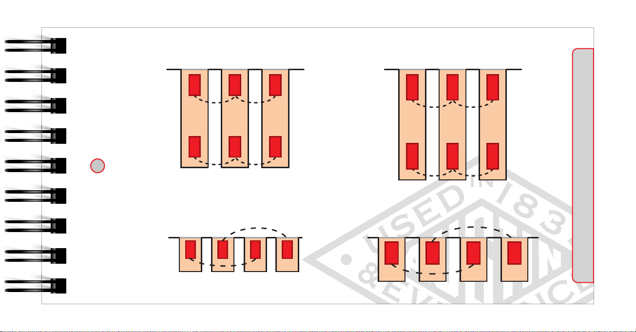
Double Priming Double Priming - example
Single Priming Single Priming - example
1st delay = 475 ms
2nd delay = 500 ms
interval = 17 ms
1 = 1st delay
2 = 2nd delay
3 = interval
1 = 1st delay
2 = 2nd delay
3 = interval
1st delay = 10 ms
2nd delay = 20 ms
interval = 20 ms
475 492 509
500 517 534
10 20 30
17 17
17 17
40
20
20
This function is used to check what values have been programmed.
“SHOW ALL” = detonator list with the cursor on the last programmed detonator. You can scroll through
the list to see the programming history
“SHOW EACH DETONATOR” - Logger will ask how you want to display the detonators.
You can choose “SEQUENTIAL BY DET#” or “ORDER DETS LOGGED”
“SELECT DETONATOR” = choose the detonator number to see detonator details
E*STAR LOGGER 2 | DETONATOR LIST
E*STAR LOGGER 2 | DETONATOR LIST
10
Once programming is completed, the detonators must be connected to the branch wires (Bus-line) according
to the programmed branch numbers. You can connect detonators to the Bus-line or use Daisy Chaining
Connection (described below).
EXAMPLE: DETONATORS THAT HAVE BEEN PROGRAMMED WITH BRANCH NUMBER 1
MUST BE CONNECTED TO BRANCH WIRE NUMBER 1.
WORKING PROCEDURE | BRANCHING
WORKING PROCEDURE | BRANCHING
11

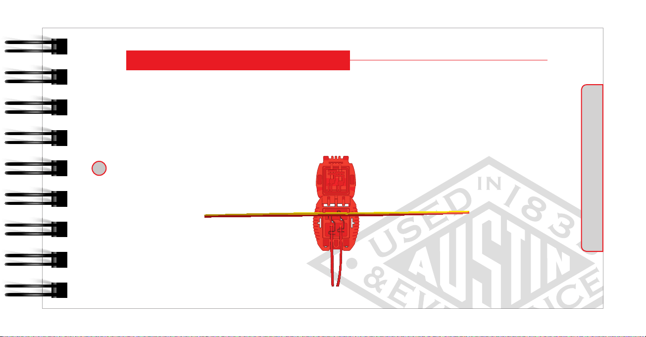
Can be used for:
Connection between branch wire and firing line
Fast extension of the firing line (Bus-line)
Fast extension of the branch wire (Bus-line)
Fast verification / leakage test from any point on firing
line or branch wire
Adding a spare connector in case of a damaged original
connector
BRANCHING | E*STAR PRONTO CONNECTOR
BRANCHING | E*STAR PRONTO CONNECTOR
12
Daisy Chaining connection is connection of one detonator to another detonator instead of Bus-line.
For illustration please see the schematic drawings below.
BRANCHING | DAISY CHAINING CONNECTION
BRANCHING | DAISY CHAINING CONNECTION
13
LESS IS MORE!
Connection between the branch and firing line can be done in several ways. It mostly depends on the connection
method in the specific branch.

The maximum number of detonators connected to one branch is 100, with Bus-line connection. A lower
number of detonators in a branch is always better for energy distribution.
If detonators are connected in the Daisy Chaining connection, the interconnection between branch and firing
line should be considered. The maximum number of detonators in one branch with Daisy Chaining connection
is 80. A lower number of detonators in the branch makes it easier to troubleshoot any issues.
Firing line length (ft)
Maximum dets per Blasting Machine (units)
Maximum detonators per Blasting Machine for E*STAR systems based on connection method
Legend:
—E*STAR Standard & Heavy Duty
(Bus-line connection)
-- E*STAR Standard
(Daisy Chaining connection = max. 80 dets/branch
& max. 19 ft connector to connector separation)
14
BRANCHING | DAISY CHAINING CONNECTION
TO ACHIEVE THE BEST ENERGY DISTRIBUTION, IT IS HIGHLY RECOMMENDED TO CONNECT
THE FIRING LINE IN THE MIDDLE OF THE BRANCHES BY USING THE E*STAR PRONTO CONNECTOR!
BRANCHING | DAISY CHAINING CONNECTION
BRANCHING | DAISY CHAINING CONNECTION
15
Austin Powder RecommendationPossible Solution
crest cresttoe toe
E*STAR
Pronto
Connector

Austin Powder RecommendationPossible Solution
16
BRANCHING | BUS-LINE CONNECTION
BRANCHING | BUS-LINE CONNECTION
crest cresttoe toe
E*STAR
Pronto
Connector
E*STAR
Pronto
Connector
Verification is the process where the Logger is connected to the branch wire. The Logger communicates with
all programmed detonators to identify any unconnected, programmed detonators (MISSING), and detonators
that may not have been programmed but are connected to the branch wire (UNEXPECTED).
All issues must be resolved before proceeding to firing. During verification, the Logger compares what is in
the memory (what was programmed) and what is connected to the branch wires.
After successful verification, the Logger performs current measurements, informing the user about potential
Leakage problems. Explanation of the function is in the next chapter.
This same process must be completed for every branch in the blast.
Remember, 100 detonators are the maximum number of detonators permitted per branch!
BRANCHING | E*STAR PRONTO CONNECTOR
BRANCHING | VERIFICATION
17

Branch leakage is measured automatically during verification as its last step.
For separate branch leakage measuring, select “LEAKAGE” in “MAIN menu” and then “BRANCH”.
Type in the branch number for which you want to measure the leakage.
The measured values will appear on the screen, along with the branch number.
The third line is the expected value (calculated based on number of detonators times current
consumption 0.1 mA).
The fourth line displays the measured values in different directions / polarities.
When the values of expected and measured match, there is no excessive leakage.
When measured values are higher than expected, there is excessive leakage in the network, which must be
identified and remedied before proceeding.
When measured values are lower than expected ones, it means there are some missing detonators. Running
a new verification of the branch is advisable to identify the issue.
BRANCHING | BRANCH LEAKAGE MEASURING
BRANCHING | BRANCH LEAKAGE MEASURING
18

What is Leakage?
A leakage occurs when current is lost through a leak. The leak is caused by the damage of insulation of the
wires. It is an Achilles heel of all electronic blasting systems since they use of low energy to carry signals to
the detonators.
Types of leakage
Ground leakage (Bus-Shell)
Only one wire core is exposed - damage of insulation on that particular conductor core
It is detectable only when using ground rod connected to the E*STAR Tester, E*STAR Logger or
E*STAR Logger 2
Proper value, which must be read on the equipment, is 0.00 mA. Higher value means ground leakage is
present. Since there is damage on only one wire, it’s important to know which polarity the leakage exists.
Detonator leakage (Bus-Bus)
Two wire cores are exposed - damage of insulation
It is detectable by E*STAR Tester, E*STAR Logger or E*STAR Logger 2
LEAKAGE TROUBLESHOOTING
LEAKAGE TROUBLESHOOTING
19

LEAKAGE TROUBLESHOOTING
20
Leakage Tolerance
Logger, Logger 2 = max. 18 mA to read and program detonator or to do branch verification.
If you have 2 dets, each 12 mA, in the same branch, you will be able to program them but not verify the branch
because total branch leakage will be higher than 18 mA.
Blasting Machine = max. 550 mA to charge detonators and fire them.
If you will have 35 branches, each 18 mA, you will be able to verify them but not to fire them because total blast
leakage will be higher than 550 mA. The real mA value on Blasting Machine will not be 35*18 = 630 mA, but
higher, because Blasting Machine’s voltage is much higher than Logger’s voltage.
Table of contents
Other AUSTIN POWDER Test Equipment manuals

Popular Test Equipment manuals by other brands

Proceq
Proceq DYNA ESTRICH operating instructions

Senior Technologies
Senior Technologies WanderGuard 18029 operating instructions

REV Ritter
REV Ritter CB-171 instruction manual

IDEAL
IDEAL 61-954 instruction manual

pico Technology
pico Technology PicoVNA 106 Programmer's guide

Tektronix
Tektronix TBS1000B-EDU Series Programmer's manual


