manuals.online logo
Brands
  1. Home
  2. •
  3. Brands
  4. •
  5. Tektronix
  6. •
  7. Test Equipment
  8. •
  9. Tektronix 515 User manual

Tektronix 515 User manual

i
ixj
str
u
cti
o
IM
ivizxrxi
ljzxl
S.
W.
Millikan
Way
•
P.O.
Box
500
•
Beaverton,
Oregon
•
Phone
MI
4-0161
•
Ca les:
Tektronix
070-247
WARRANTY
All
Tektronix
instruments
are
warranted
against
defective
materials
and
workman

ship
for
one
ear.
Tektronix
transformers,
manufactured
in
our
own
plant,
are
war

ranted
for
the
life
of
the
instrument.
An
questions
with
respect
to
the
war

rant
mentioned
above
should
be
taken
up
with
our
Tektronix
Field
Engineer.
Tektronix
repair
and
replacement-part
service
is
geared
directl
to
the
field,
there

fore
all
requests
for
repairs
and
replace

ment
parts
should
be
directed
to
the
Tek

tronix
Field
Office
or
Representative
in
our
area.
This
procedure
will
assure
ou
the
fastest
possible
service.
Please
include
the
instrument
T pe
and
Serial
number
with
all
requests
for
parts
or
service.
Specifications
and
price
change
priv

ileges
reserved.
Cop right
©
1960
b
Tektronix,
Inc.,
Beaverton,
Oregon.
Printed
in
the
United
States
of
America.
All
rights
reserved.
Con

tents
of
this
publication
ma
not
be
repro

duced
in
an
form
without
permission
of
the
cop right
owner.
Type
515/515A
AA
CONTENTS
Section
1
Section
2
Section
3
Section
4
Section
5
Warranty
Specifications
Operating
Instructions
Circuit
Description
Maintenance
Recali ration
Procedure
Section
6
Parts
List
and
Schematic
Diagrams
Section
7
Accessories
AA
Type
515/515A
http://manoman.sqhill.com
INTtNSITY
MMJAit-W**
1
ERTICAL
IN»U>
SIlKTOt
TYPE
5J5A
OSCILLOSCOPE
SltlAL
TKM
SC
Alt
M-llM*
ASTIGMATISM
POSITIONING
------------
)
H0«0***
2SK^-
Mfr
nwStwo
«
*
<
Y
Type
515/5
ISA
AA
http://manoman.sqhill.com
ON
1
IFICATIONS
The
Type
515/515A
Oscilloscope
is
a
compact,
porta le,
general
purpose
oscilloscope.
The
dc-coupled
amplifier
and
wide
range
of
sweep
rates,
com ined
with
reduced
size,
make
the
Type
515/515A
a
versatile
field
or
la oratory
instrument.
ertical-Deflection
System
Deflection
Factor-.
05
volt/cm
ac
or
de.
(.1
volt/cm
ac
or
de
S/N
101-1000)
Frequency
Response-dc
to
15
me,
2
cycles
to
15
me
ac.
(Down
not
more
than
3
d
at
a ove
limits.)
Rise
Time-.
023
microseconds.
Linear
Deflection-6
cm.
Step
Attenuator-Nine
positions,
cali rated,
from
.05
v/cm
(.1
v/cm
S/N
101-1000)
to
20
v/cm,
(50
v/cm
S/N
101-1000)
accurate
within
3%
when
set
on
any
one
step.
Maximum
Allowa le
Com ined
DC
and
Peak
AC
Voltage
Input
-600
v.
Input
Impedance-
1
megohm,
30
ggf;
with
P410
pro e-10
megohm,
10.5
ggf.
With
P6000
pro e,
10
megohm,
11.5
ggf.
Horizontal-Deflection
System
Time
Base
Range
Twenty-two
cali rated
time
ases
from
.2
gsec/cm
to
2
sec/cm.
Accuracy-3
per
cent.
Continuously
varia le,
uncali rated
etween
ranges
and
to
6
sec/cm.
Magnifier
Expands
sweep
5
times
to
right
and
left
of
screen
center.
Extends
fastest
sweep
rate
to
.04
gsec/cm.
Accuracy-5
per
cent.
Un lanking-DC
coupled.
Trigger
Requirements
Internal-2
mm
of
deflection.
External-.
2
volts
to
20
volts.
Frequency
Range-dc
to
15
me.
Horizontal
Input
Deflection
Factor-1.4
v/cm.
Frequency
Response-DC
to
500
kc
,
3
d
down.
Other
Characteristics
Cathode-Ray
Tu e
Type
T55P2.
Pl,
P7,
and
Pll
phosphors
optional.
Accelerating
Potential-4,
000
volts.
Deflection
Factor
at
Plates
Vertical-5
v/cm.
Horizontal-20
v/cm.
Voltage
Cali rator
Eleven
fixed
voltages
from
.05
volts
to
100
volts,
peak
to
peak.
Accuracy-3
per
cent.
Waveform-square
wave
at
a out
1
kc.
Output
Waveforms
Availa le
Positive
gate
of
same
duration
as
sweep,
approx.
20
volts.
Positive
going
sweep
saw

tooth,
150
volts.
Power
Supply
Electronic
Regulation.
Power
Requirements-
105
to
125,
or
210
to
250
v,
50-60
cycles,
275
watts.
A
A
Specifications
-
Type
515/515A
1-1
Accessories
Included
Mechanical
Specifications
Ventilation-Filtered,
forced-air
ventilation.
1-P6017
pro e.
Finish
-
Photo-etched,
anodized
panel,
lue
wrinkle,
perforated
ca inet.
1-A510
Binding
Post
Adapter.
1-F510-5
green
filter.
Dimensions-9
3/4"
wide,
13
1/2"
high,
211/2"
deep.
1
-Instruction
manual.
Weight
-40
pounds.
1-2
Specifications
-
Type
515/515A
EXPORT
POWER
TRANSFORMER
Transformer
Primary
The
instrument
fur
which
this
manual
was
prepared
is
equipped
with
a
special
transformer.
The
transformer
has
eight
primary
terminals
making
possi le
six
different
input
connections.
The
six
primary
connections
are
shown
in
Fig.
1.
POWER
TRANSFORMER
HAS
TWO
NOMINAL
PRIMARY
OLTAGES
OF
50
OR
60
a
,
OPERATION.
A
EXTRA
WINDINGS
PERMITTING
110,
117,
124,
220,
234,
OR
248
,
z
5
z
5
c
110
*
D
2
I
1
t
3
u
4
117
f
D
D
A
/
/
2
3
B
1
*
124
B
1
t
1
t
o
c
4
t
A
4
t
4
220
t
B
C
1
t
248
D
i
>
D
A
4
A
B
A
2 3
BC
1
4
t
234
t
Fig.l.
The
power
transformer
has
two
extra
windings
permitting
nominal
primary
voltages
of
110,
117,
124,
220,
234,
248
volts,
50
or
60
cycle
operation.
Fig.
2.
When
connecting
the
power
transformer
for
operation
with
a
supply
voltage
of
200
volts
or
more,
e
sure
that
the
fan
is
connected
etween
pins
1
and
3
of
the
primary.
This
is
to
insure
that
the
fan
is
supplied
with
no
more
than
125
volts.
Fig.
2
shows
a
typical
high-voltage
fan
connection,
using
as
an
example
the
wiring
for
a
248
volt
supply.
General
Information
The
Type
515/515A
Oscilloscopes
are
extremely
versatile
instruments,
adapta le
to
a
great
num er
of
applications.
However,
to
make
use
of
the
full
potentialities
of
the
instru

ment,
it
is
necessary
that
you
understand
com

pletely
the
operation
of
each
control.
This
portion
of
the
Operators
Manual
is
intended
to
provide
you
with
the
asic
information
that
you
require.
If
you
are
familiar
with
other
Tektronix
oscilloscopes,
you
should
have
very
little
difficulty
in
understanding
the
operation
of
the
515/515A,
since
the
function
of
many
of
the
controls
is
the
same
as
the
function
of
corresponding
controls
in
other
Tektronix
instruments.
Cooling
Unless
tagged
otherwise,
this
oscilloscope
is
connected
at
the
factory
for
117
-volt
operation.
For
234-
volt
operation,
refer
to
the
Maintenance
section
of
this
manual
for
proper
transformer
connections.
FIRST-TIME
OPERATION
Control
Settings
The
following
procedure
will
help
you
get
a
trace
on
the
screen
and
ecome
familiar
with
some
of
the
controls.
Connect
the
line
cord
to
a
sorce
of
117-
volt
50
to
60
cycle
power,
and
set
the
front

panel
controls
as
follows:
A
fan
maintains
safe
operating
temperature
in
the
Type
515/515A
Oscilloscope
y
circulat

ing
air
through
a
filter
and
over
the
rectifiers
and
other
components.
The
instrument
must
therefore
e
placed
so
the
air
intake
is
not
locked.
The
air
filter
must
e
kept
clean
to
permit
adequate
air
circulation.
If
the
interior
temperature
does
rise
too
high
lor
some
reason,
a
thermal
cutout
switch
will
disconnect
the
power
and
keep
it
disconnected
until
the
temperature
drops
to
a
safe
value.
Power
Requirements
The
regulated
power
supplies
in
the
Type
515/515A
will
operate
with
line
voltages
from
105
to
125
volts
or
from
210
to
250
volts.
For
maximum
dependa ility
and
long
tu e
life
the
voltage
should
e
near
the
center
of
this
range.
Voltages
outside
of
these
limits
may
cause
hum
or
jitter
on
the
trace.
Be
sure
the
line
voltage
is
correct
if
indications
such
as
these
are
present.
FOCUS
Centered
INTENSITY
ASTIGMATISM
POWER
INPUT
SELECTOR
VOLTS/CM
( lack
kno )
Counterclockwise
(CCW)
Centered
ON
INPUT
1,
DC
5
TRIGGER
SELECTOR
lack
kno
+
INT
red
kno
AUTO
TRIGGERING
LEVEL
STABILITY
(red
kno )
HOR1Z.
DISPLAY
Counterclockwise
PRESET
(CCW
S/N
101-1000)
NORM.
AA
Operating
Instiuctions
-
Type
515/515A
2-1
.5
MILLISEC
TIME/CM
VERTICAL
POSITIONING
Center
HORIZONTAL
POSITIONING
Center
CALIBRATOR
10
Connect
a
lead
from
the
CAL.
OUT
con
nector
to
the
INPUT
1
connector.
If
the
tu es
have
had
time
to
warm
up,
turn
the
INTENSITY
control
clockwise
until
a
trace
is
visi le
on
the
screen.
Adjust
the
FOCUS,
ASTIGMATISM
and
INTENSITY
controls
to
produce
a
sharp
trace
of
comforta le
rightness.
The
two
POSITIONING
controls
will
move
the
trace
vertically
and
horizontally
as
nec

essary
to
position
the
display
where
you
want
it
on
the
crt
screen.
Triggering
Modes
If
you
have
not
had
previous
experience
with
the
type
of
trigger
controls
used
on
this
oscilloscope,
the
cali rator
waveform
is
a
good
one
to
practice
with.
A
few
minutes
spent
on
trying
the
triggering
modes
descri ed
elow
will
e
time
well
spent
in
terms
of
future
operating
convenience.
Auto
The
triggering
method
used
in
the
preceeding
example
is
the
AUTO,
(automatic)
mode
of
operation.
It
is
the
simplest
mode
of
triggering.
There
are
no
front-panel
controls
to
e
adjusted
when
using
this
mode.
If
the
signal
is
removed
from
the
input
connector,
the
sweep
will
con

tinue,
ut
at
a
reduced
repetition
rate.
This
provides
a
visual
indication
that
the
signal
has
een
removed
and
the
sweep
and
triggering
circuits
are
operating.
AC
Now
try
the
AC
mode
of
triggering.
Turn
the
red
TRIGGER
SELECTOR
kno
to
AC.
Advance
the
TRIGGERING
LEVEL
control
clockwise
until
you
get
a
sta le
trace.
There
may
e
a
considera le
range
over
which
you
get
a
sta le
trace.
The
start
of
the
trace
will
move
up
and
down
the
edge
of
the
square
wave
over
this
range.
Notice
that
the
trace
starts
on
the
up-going
part
of
the
cali rator
square
wave.
Now
turn
the
lack
TRIGGER
SELECTOR
switch
to
the
-INT
position
and
readjust
the
TRIGGERING
LEVEL
control
to
get
a
sta le
trace
again.
Notice
now
that
the
trace
starts
on
the
down-going
portion
of
the
square
wave
and
that
the
position
of
the
start
can
again
e
changed
somewhat
with
the
level
control.
DC
Turn
the
red
TRIGGER
SELECTOR
kno
to
DC.
If
necessary
adjust
the
TRIGGERING
LEVEL
control
for
sta le
triggering.
Move
the
trace
vertically
on
the
screen
with
the
VERTICAL
POSITIONING
control
and
note
that
triggering
occurs
at
a
vertical
level
on
the
screen
selected
y
the
LEVEL
control,
and
that
the
triggering
point
changes
relative
to
the
waveform
as
the
waveform
is
positioned
vertically.
This
effect
will
e
more
noticea le
if
you
look
at
a
low-frequency
sine
wave.
H
F
Sync
The
H
F
SYNC
position
of
the
TRIGGERING
SELECTOR
switch
is
primarily
for
signals
having
a
repetition
rate
in
excess
of
five
megacycles.
In
this
position
the
time
ase
will
trigger
poorly,
if
at
all,
on
the
cali rator
waveform.
To
sta ilize
the
display
of
a
high-
frequency
signal
,
simply
advance
the
STABILITY
control
clockwise
until
a
sta le
trace
is
o tained.
The
LEVEL
control
is
not
used
in
the
H
F
SYNC
mode.
FUNCTIONS
OF
CONTROLS
AND
CONNECTORS
CRT
Controls
FOCUS
INTENSITY
Control
to
adjust
the
eam
for
maximum
sharpness
of
the
trace.
Control
to
vary
the
rightness
of
the
trace.
2-2
Operating
Instructions
-
Type
515/515A
AA
Fig.
2-2.
Sweep
controls
in
typical
position
for
AC
mode
of
triggering.
This
mode
is
useful
for
general-purpose
triggering
over
the
range
from
60
cps
to
5
me.
F
ig.
2-1.
Sweep
controls
in
typical
position
for
AUTO
mode
of
trigger

ing.
This
mode
is
the
most
convenient
triggering
method
over
the
frequency
range
from
60
cps
to
2
me.
C
TIME
BASE
A
I
INPUT
TRIGGER
SELECTOR
(
TIME
BASE
moote
>
INPUT
AA
STABILITY
OK
HOIIZ
INFUT
ATTIN
TRIGGERING
LE EL
Fig.
2-3.
Sweep
controls
in
typical
position
for
DC
mode
of
triggering.
This
mode
is
particularly
useful
for
the
frequency
range
elow
60
cps.
STABILITY
0*
HOtll
*rut
ATTfN.
TRIGGERING
LE EL
Fig.
2-4.
Sweep
controls
in
typical
position
for
HF
SYNC
mode
of
sweep
synchronization.
This
mode
is
most
effective
a out
5
me.
Operating
Instructions
-
Type
515/515A
2-3
http://manoman.sqhill.com
Time-Base
Generator
ASTIGMATISM
Control
used
in
conjunction
with
the
FOCUS
control
to
adjust
the
eam
for
maximum
sharpness
of
the
trace.
SCALE
ILLUM.
Control
to
vary
the
rightness
of
the
graticule
illumination.
VERTICAL
POSITIONING
Control
to
position
the
trace
vertically.
HORIZONTAL
POSITIONING
Control
to
position
the
trace
horizontally.
TRIGGER
SELECTOR
(red
kno )
Four-position
switch
to
select
four
kinds
of
triggering:
H
F
SYNC,
AUTO,
AC
and
DC.
TRIGGER
SELECTOR
( lack
kno )
Six-position
switch
to
select
the
source
and
polarity
of
the
triggering
signal.
TRIGGER
INPUT
Coax
connector
to
triggering
circuits.
STABILITY
Control
to
adjust
time- ase
circuits
for
triggered
or
recurrent
operation.
This
control
has
a
PRESET
position
suita le
for
most
triggering
applications
(S/N
1001
-up).
This
control
also
functions
as
an
attenuator
for
external
signals
connected
to
the
EXT.
HORIZ.
INPUT
inding
post.
TRIGGERING
LEVEL
Control
to
select
the
point
on
the
triggering
waveform
where
the
time
ase
egins.
HORIZ.
DISPLAY
Three-position
switch
to
increase
the
sweep
rate
five
times
in
the
MAG.
position
and
to
connect
the
horizontal
amplifier
to
the
EXT.
HORIZ.
INPUT
inding
post
in
the
EXT.
position.
When
this
control
is
in
the
MAG.
position,
the
MAG.
light
indicates
that
the
sweep
rate
has
een
increased
five
times.
EXT.
HORIZ.
INPUT
Binding
post
to
apply
an
external
signal
to
the
horizontal
amplifier.
T1ME/CM
Twenty-two-position
switch
to
select
cali rated
sweep
rates
from
2
sec/cm
to
.2
gsec/cm.
VARIABLE
(red
kno )
Continuously
varia le
control
to
vary
the
sweep
rate
etween
ranges
and
to
5
sec/cm.
When
this
control
is
away
from
the
clockwise
stop
the
UNCALIBRATED
light
indicates
that
the
time
ase
is
not
cali rated.
ertical
Amplifier
INPUT
1
INPUT
2
Separate
signal
inputs
to
the
vertical
amplifier
y
way
of
the
INPUT
SELECTOR
switch.
INPUT
SELECTOR
Four-position
switch
to
select
either
input
connector
and
insert
or
remove
a
de
locking
capacitor
from
the
input
circuits.
DC
BAL.
Screwdriver
control
to
alance
the
amplifier
circuits
so
that
there
is
no
shift
in
the
trace
position
as
the
VARIABLE
control
is
rotated.
2-4
Operating
Instructions
-
Type
515/515A
AA
Auxiliary
Functions
VOLTS/CM
Nine-position
switch
to
select
the
desired
deflection
sensitivity.
VARIABLE
Continuously
varia le
control
to
vary
the
sensitivity
etween
ranges
and
to
50
volts/cm.
When
this
control
is
away
from
the
clockwise
stop
the
UNCALIBRATED
light
indicates
that
the
amplifier
is
not
cali rated.
Rear
Panel
+
GATE
Binding
post
to
supply
a
positive
pulse
for
the
duration
of
the
time
ase.
SAWTOOTH
OUT
Binding
post
to
supply
a
positive-going
sawtooth,
synchronized
with
the
internal
time
ase.
SQUARE-WAVE
CALIBRATOR
Twelve-position
switch
to
select
one
of
eleven
taps
on
a
precision
voltage
divider
in
the
cali rator
circuit
and
to
turn
the
cali rator
off.
CAL.
OUT
Coax
connector
from
the
cali rator.
POWER
On-off
switch
in
the
lead
to
the
power
transformer
and
fan.
TRIGGERING
INSTRUCTIONS
CRT
CATHODE
Binding
post
to
the
ert
cathode
for
the
application
of
intensity
modulation.
General
The
function
of
the
trigger
circuit
is
to
derive
from
the
incoming
waveform
a
sharp
pulse
of
suita le
amplitude
to
trigger
the
time- ase
generator.
One
such
pulse
occurs
for
each
cycle
of
the
incoming
waveform.
This
pulse
is
independent
of
the
incoming
waveform
in
shape
and
amplitude.
The
time- ase
generator
develops
the
saw

tooth
waveform
necessary
to
provide
a
linear
time
ase.
If
the
STABILITY
control
is
set
for
triggered
operation,
the
time
ase
circuits
wait
until
a
trigger
pulse
is
received,
at
which
time
one
sawtooth
waveform
is
produced.
After
the
sawtooth
waveform
is
completed
the
time
ase
circuits
wait
for
the
next
trigger
pulse
and
the
process
is
repeated.
The
following
paragraphs
descri e
the
function
of
the
controls
which
affect
this
operation.
Later
paragraphs
descri e
specific
triggering
procedures.
Triggering
Controls
Triggering
Level
In
the
Type
515/515A
the
TRIGGERING
LEVEL
control
determines
the
point
on
the
triggering
waveform
at
which
triggering
will
occur.
The
TRIGGERING
LEVEL
control
is
not
a
trigger
amplitude
or
gain
control
if
you
are
accustomed
to
this
type
of
circuit.
Instead,
it
is
an
amplitude
or
voltage
discriminator.
If
the
waveform
you
are
o serving
is
centered
on
the
screen
and
the
TRIGGERING
LEVEL
control
is
set
near
0
the
sweep
will
start
as
the
waveform
passes
through
the
center
line
on
the
screen.
As
the
LEVEL
control
is
turned
clockwise,
the
triggering
point
will
move
a ove
the
center
line
on
the
screen,
and,
as
it
is
turned
counter

clockwise
the
triggering
point
will
move
elow
the
center
line.
If
the
LEVEL
control
is
set
for
a
voltage
greater
than
that
of
the
waveform
eing
o served
the
sweep
will
stop.
Thus,
if
the
waveform
is
of
low
amplitude
the
LEVEL
control
should
e
set
near
0
(or
near
the
de
level
with
DC
triggering).
The
LEVEL
control
is
used
only
in
the
AC
and
DC
positions
of
the
TRIGGER
SELECTOR
switch.
AA
Operating
Instructions
-
Type
515/515A
2-5
+s
l
OP
E
ilia
ilia
iiil
f
T
T
T
ft*
’
’
-s
OP
Fig.
2-6.
Photograph
showing
the
phase-shifting
effect
of
the
TRIGGER

ING
LEVEL
control.
All
waveforms
were
o tained
with
the
TRIGGER
SELECTOR
set
at
+
INT.
Fig.
2-5.
Photograph
showing
the
effect
of
the
+
and
-
positions
of
the
lack
TRIGGER
SELECTOR
kno .
iiii
A
1^
1
till
1
i
1111
ih
i
i
1
’
'
T
I
1
i
r
B
1
Ft
T
*
ill!
r
•
Fig.
2-8.
Photograph
showing
an
application
of
the
level
selection
a ility
of
the
TRIGGERING
LEVEL
control.
By
setting
the
LEVEL
control
to
the
+
side
of
the
0
mark,
the
trigger
circuits
can
e
made
to
reject
all
of
the
waveform
except
the
highest
peaks.
Fig.
2-7.
To
trigger
along
slope
A
set
the
lack
TRIGGER
SELECTOR
kno
to
+.
Use
the
positions
marked
-
to
trigger
along
slope
B.
For
maximum
trace
sta ility,
trigger
on
the
fastest
rising
or
falling
portion
of
a
waveform.
t
i
Ji
i
Ai
i
/ill
L
1
1
1
1111
1
11L
iili
4
M
4
,
T
tit
t
flit
T
T
•
t
1
1
itr
■
*♦
w
X
X
j
a
a
i
i
T
f
T
Fig.
2-9.
Photograph
showing
a
waveform
where
external
triggering
may
e
needed
to
examine
a
small
discontinuity
in
a
larger
waveform.
Usually
a
triggering
waveform
can
e
o tained
which
is
synchronized
with
the
discontinuity.
F
ig.
2-10.
A
triple-exposure
photograph
of
a
waveform
showing
the
effect
of
positioning
on
the
triggering
point
when
using
the
DC
triggering
mode.
The
TRIGGER
SELECTOR
controls
are
set
at
4-
INT,
DC
and
the
TRIGGERING
LEVEL
control
is
at
0.
2-6
Operating
Instructions
-
Type
515/515A
AA
Trigger
Slope
The
lack
TRIGGER
SELECTOR
kno
selects
the
trigger
source
and
determines
whether
the
sweep
will
start
as
the
waveform
is
going
positive
or
negative.
The
+
positions
of
this
switch
cause
triggering
to
occur
during
the
rising
portion
of
the
waveform.
The
-
positions
cause
triggering
to
occur
during
the
falling
portion
of
the
waveform.
The
trigger
slope
feature
is
not
used
in
the
H
F
SYNC
mode.
Triggering
Mode
The
red
TRIGGER
SELECTOR
kno
selects
the
kind,
or
mode,
of
triggering
used.
The
DC
position
will
permit
triggering
on
all
signals
from
de
to
a out
five
megacycles.
It
is
especially
useful
for
signals
elow
60
cycles
where
the
sensitivity
of
AC
triggering
egins
to
fall
off.
In
the
AC
position,
the
switch
inserts
a
capacitor
in
the
trigger
circuits
to
make
the
trigger
settings
independent
of
the
vertical
position
of
the
trace.
This
mode
is
slightly
more
sensitive
than
the
DC
mode.
The
AUTO
position
arranges
the
circuits
for
an
automatic
synchronizing
action
rather
than
a
strict
triggering
action.
In
this
position
the
trigger-shaper
multivi rator
free-runs
at
a
repetition
rate
of
a out
50
cycles.
The
multivi rator
will
lock
in
and
run
synchronously
with
trigger
signals
from
60
cycles
to
a out
2
megacycles.
If
the
trigger
signal
is
lost
the
sweep
will
not
stop
ut
will
continue
at
a
reduced
repetion
rate
without
synchronization.
In
the
H
F
SYNC
position
the
trigger-shaper
circuits
are
ypassed
and
the
triggering
wave

form
is
used
to
synchronize
the
time
ase
circuits
directly.
The
time- ase
generator
must
e
free-running
for
this
type
of
operation.
It
free-runs
at
advanced
settings
of
the
STABILITY
control.
This
mode
of
operation
is
primarily
useful
for
signals
in
excess
of
two
megacycles.
Stability
The
STABILITY
control
adjusts
the
ias
level
on
a
multivi rator
in
the
time- ase
generator
near
the
level
at
which
the
sweep
will
free-run.
Three
principal
settings
of
the
STABILITY
control
are
used;
the
first
setting
is
with
the
control
advanced
to
the
right,
past
the
point
where
thegenerator
free-runs;
second,
retarded
to
the
left
just
past
the
point
where
free-running
ceases;
and
third,
retarded
all
the
way
left
to
make
the
generator
inoperative.
The
second
setting
is
duplicated
y
an
internal
circuit
when
the
STABILITY
control
is
rotated
to
the
PRESET
position.
When
the
time- ase
generator
free-runs,
the
sawtooth
waveforms
are
produced
at
a
repetition
rate
determined
y
the
generator
circuit
itself.
The
STABILITY
control
varies
this
repetition
rate
slightly.
In
the
second,
or
triggered,
position
of
the
STABILITY
con

trol
the
time- as
j
generator
does
not
run
until
a
trigger
pulse
is
received
at
which
time
one
sawtooth
waveform
is
produced
and
the
generator
waits
for
the
next
trigger
pulse.
This
is
also
the
case
when
the
STABILITY
control
is
set
at
PRESET.
For
synchronized
operation
of
the
time- ase
generator,
as
used
in
the
H
F
SYNC
position,
set
the
STABILITY
control
to
the
advanced
position
so
that
the
generator
just
free-runs,
and
keep
it
to
the
right
of
this
point
while
adjusting
its
point
to
synchronize
the
time
ase.
For
all
triggered
operation
except
AUTO.
,
the
STABILITY
control
should
e
retarded
to
the
left
of
the
free
run
point
or
set
to
the
PRESET
position
(S/N
1001
-up).
General-Purpose
Triggering
For
most
average
triggering
applications
the
AUTO,
mode
of
triggering
is
the
easiest
to
use.
Only
one
control
need
e
adjusted
and
after
it
is
once
set
the
sweep
will
trigger
satisfactorily
on
a
wide
variety
of
waveforms
and
over
a
wide
range
of
sweep
speeds
without
resetting.
When
the
STABILITY
control
is
set
properly
there
will
always
e
a
trace
on
the
screen,
whether
a
signal
is
present
or
not,
unless
the
trace
is
positioned
off
the
screen
vertically.
This
feature
is
especially
valua le,
if
the
pro e
is
eing
moved
from
one
point
to
another
in
a
circuit
under
test.
To
use
the
AUTO,
mode,
set
the
red
TRIGGER
SELECTOR
kno
to
AUTO.
A
horizontal
trace
should
appear
immediately.
A
sta le
display
should
e
o tained
on
most
signals
within
the
range
of
60
cycles
to
2
megacycles
when
using
this
mode.
AA
Operating
Instructions
-
Type
515/515A
2-7
For
any
application
within
the
frequency
range
from
60
cycles
to
a out
5
megacycles
where
the
display
is
unsta le
on
AUTO.,
the
AC
mode
can
e
used.
To
use
this
mode
of
triggering,
proceed
as
follows:
1.
Set
the
red
TRIGGER
SELECTOR
kno
to
AC.
2.
Set
the
STABILITY
control
to
the
PRESET
position
(counterclockwise
S/N
101-1000).
3.
Adjust
the
TRIGGERING
LEVEL
control
for
sta le
triggering.
The
procedure
outlined
a ove
will
provide
sta le
triggering
for
most
applications.
How

ever,
with
some
triggering
waveforms
,
it
may
e
necessary
to
manually
set
the
STABILITY
control.
This
is
done
as
follows:
1.
Set
the
red
TRIGGER
SELECTOR
kno
to
AC.
2.
Turn
the
TRIGGERING
LEVEL
control
counterclockwise
to
the
stop.
3.
Advance
the
STABILITY
control
clockwise
until
the
time- ase
generator
free-runs
then
ack
it
off
just
past
the
point
where
the
sweep
s
tops
.
4.
Turn
the
TRIGGERING
LEVEL
control
clockwise
until
sta le
triggering
occurs.
With
this
same
control
you
can
now
select
the
point
or
level
at
which
triggering
occurs.
Triggering
should
occur
near
the
0
mark.
Low-Frequency
Triggering
For
waveforms
having
a
slow
rise
and
a
repetition
rate
of
less
than
60
cps,
the
DC
triggering
mode
is
est.
To
use
this
mode
of
triggering,
proceed
as
follows:
1.
Set
the
red
TRIGGER
SELECTOR
kno
to
DC.
2.
Set
the
STABILITY
control
to
the
PRESET
position
(counterclockwise
S/N
101-1000).
3.
Adjust
the
TRIGGERING
LEVEL
control
for
sta le
triggering.
The
procedure
outlined
a ove
will
provide
sta le
triggering
for
most
applications.
How

ever,
with
some
triggering
waveforms
,
it
may
e
necessary
to
manually
set
the
STABILITY
control.
This
is
done
as
follows:
1.
Set
the
TRIGGER
SELECTOR
red
kno
to
DC.
2.
Turn
the
TRIGGERING
LEVEL
control
counterclockwise
to
the
stop.
3.
Advance
the
STABILITY
control
clockwise
until
the
time- ase
generator
free-runs
then
ack
it
off
just
past
the
point
where
the
sweep
stops.
4.
Turn
the
TRIGGERING
LEVEL
control
clockwise
until
sta le
triggering
occurs.
With
this
same
control
you
can
now
select
the
point
or
level
at
which
triggering
occurs.
Triggering
should
occur
near
the
0
mark
if
the
trace
is
centered.
Since
the
AC
mode
is
more
sensitive
than
the
DC
mode
a ove
60
cps
and
is
not
affected
y
the
positioning
controls,
it
is
superior
to
the
DC
mode,
a ove
60
cps.
However,
the
DC
mode
can
e
used
up
to
a out
5
me.
High-Frequency
Synchronization
For
sta le
triggering
it
is
necessary
for
the
trigger
circuits
to
have
a
frequency
response
considera ly
in
excess
of
the
frequency
of
the
waveform
eing
displayed.
At
a out
five
mega

cycles
the
efficiency
of
the
trigger
circuits
is
reduced
and
the
H
F
SYNC
mode
ecomes
the
est
method
of
synchronizing
the
trace.
To
use
the
H
F
SYNC
mode
simply
advance
the
STABILITY
control
until
the
time
'
ase
free-runs
and
then
continue
to
advance
it
until
the
time
ase
locks
in
with
the
signal.
The
polarity
markings
on
the
TRIGGER
SELECTOR
switch
have
no
significance
in
this
mode,
and
the
TRIGGERING
LEVEL
con

trol
is
not
used.
Triggering
on
Complex
Waveforms
When
the
waveform
under
o servation
is
complex
there
may
e
several
points
on
the
waveform
where
ordinary
triggering
circuits
may
tend
to
trigger.
As
a
result,
the
trace
may
e
unsta le.
This
insta ility
may
e
encountered
occasionally
with
the
AUTO,
mode
of
triggering.
The
AC
and
DC
triggering
modes
allow
the
level
on
a
waveform,
at
which
trigger

ing
occurs,
to
e
selected
y
the
TRIGGERING
2-8
Operating
Instructions
-
Type
515/515A
AA
LEVEL
control.
Thus
the
LEVEL
control
can
e
set
so
that
only
one
point
on
the
waveform
is
of
sufficient
amplitude
to
trip
the
triggering
circuits.
This
point
can
e
located
y
setting
the
controls
as
for
the
AC
or
DC
triggering
modes
and
then
moving
the
TRIGGERING
LEVEL
control
away
from
the
0
mark
in
either
direction
until
the
trace
ecomes
sta le.
Trigger-Signal
Source
For
most
normal
triggering
applications
the
1NT.
trigger
source
is
most
convenient.
In
the
INT.
positions
of
the
TRIGGER
SELECTOR
switch
the
triggering
signal
is
o tained
from
the
vertical
amplifier.
If
an
external
trigger
source
is
availa le
it
is
often
convenient
to
use
the
EXT.
positions
of
the
TRIGGER
SELECTOR
switch.
An
external
trigger
source
is
particularly
useful
if
the
amplitude
of
the
signal
under
o servation
is
changing
or
if
the
pro e
is
eing
moved
from
point
to
point
in
a
circuit.
The
LINE
positions
of
the
TRIGGER
SELECTOR
switch
permit
sta le
triggering
at
the
line
frequency.
These
positions
are
useful
when
displaying
almost
any
function
that
is
synchronized
with
the
line.
TIME-BASE
OPERATION
General
The
time- ase
generator
produces
the
saw

tooth
waveform
which
is
used
to
move
the
eam
across
the
crt.
The
TIME/CM
controls
vary
the
slope,
ut
not
the
amplitude,
of
this
waveform,
and
thus
determine
the
sweep
rate
without
affecting
the
length
greatly.
The
horizontal
amplifier
amplifies
the
saw

tooth
waveform
and
applies
it
to
the
crt
deflection
plates.
The
HORIZ.
DISPLAY
switch
increases
the
gain
of
the
amplifier
five
times
in
the
MAG.
position.
In
this
position
the
display
is
spread
over
the
equivalent
of
five
screen
diameters.
Sweep
Rate
The
TIME/CM
controls
determine
the
sweep
rate
of
the
horizontal
trace.
The
TIME/CM
of
horizontal
deflection
is
indicated
y
the
lack
num ers
when
the
HORIZ.
DISPLAY
switch
is
in
the
normal
position
and
y
the
lue
num ers
when
it
is
in
the
MAG.
position.
These
num ers
are
correct
only
when
the
red
VARIABLE
control
is
completely
clock

wise.
The
UNCALIBRATED
light
indicates
when
the
time
ase
is
not
cali rated
for
this
reason.
The
VARIABLE
control
has
a
range
of
a out
2
1/2
to
1.
Magnifier
The
HORIZ.
DISPLAY
switch
increases
the
horizontal-amplifier
gain
five
times
in
the
MAG.
position
expanding
the
time
ase
so
that
the
center
one-fifth
of
the
trace
fills
the
graticule.
The
MAG.
light
is
energized
when
the
HORIZ.
DISPLAY
switch
is
turned
to
the
MAG.
position.
Any
portion
of
the
trace
may
e
positioned
on
the
screen
with
the
HORIZONTAL
POSITIONING
control.
If
the
VARIABLE
control
is
fully
clockwise
the
magnified
sweep
rate
is
indicated
y
the
lue
num ers
at
the
TIME/CM
switch.
External
Horizontal
Input
When
the
HORIZ.
DISPLAY
switch
is
in
the
EXT.
position,
the
horizontal
amplifier
is
con

nected
to
the
EXT.
HORIZ.
INPUT
inding
post.
The
STABILITY
control
serves
as
an
attenuator
for
signals
applied
to
this
inding
post.
ERTICAL-AMPLIFIER
OPERATION
Probes
The
P6000
pro e
furnished
with
this
instru

ment
has
a
10-to-l
attenuation
ratio.
Be
sure
to
check
the
adjustment
of
the
pro e
regularly
and
efore
making
critical
measurements.
If
the
compensation
is
incorrect
the
frequency
response
will
e
affected.
Touch
the
pro e
tip
to
the
cali rator
output
connector
and
display
several
cycles
of
the
cali rator
wave

form.
If
the
top
and
ottom
of
the
displayed
square
wave
are
not
flat,
adjust
the
trimmer
capacitor
located
inside
the
pro e
ody
to
achieve
correct
square-wave
response.
Input
Connections
Be
careful
that
the
external
circuitry
does
not
cause
deterioration
of
the
waveform
when
you
make
connections
to
the
INPUT
connectors.
Improper
termination
of
ca les
may
cause
ring

AA
Operating
Instructions
-
Type
515/515A
2-9
ing
or
loss
of
frequency
response.
If
you
use
unshielded
leads
keep
them
as
short
as
possi le.
Two
ca les
or
pro es
can
e
connected
to
the
oscilloscope
at
once.
You
can
then
select
the
signal
on
either
ca le
with
the
INPUT
SELECTOR
switch.
However,
if
one
signal
is
very
much
larger
than
the
other,
some
crosstalk
may
occur
and
the
ca le
having
the
larger
signal
should
e
disconnected.
Coupling
It
is
sometimes
unnecessary
or
undesira le
to
display
the
de
level
of
the
waveform.
In
the
two
AC
positions
of
the
INPUT
SELECTOR
switch,
a
capacitor
in
series
with
the
input
locks
the
de
component
of
the
waveform
so
that
only
the
ac
component
is
displayed.
Deflection
Sensitivity
The
VOLTS/CM
switch
inserts
frequency-
compensated
attenuators
ahead
of
the
amplifier.
The
VARIABLE
control
provides
continuous
adjustment
of
the
deflection
sensitivity
etween
the
values
indicated
y
the
VOLTS/CM
switch.
The
VARIABLE
control
must
e
clockwise
against
the
stop
for
the
sensitivity
to
e
as
indicated
y
the
VOLTS/CM
switch.
The
red
UNCALIBRATED
light
indicates
when
the
VARIABLE
control
is
not
fully
clockwise.
DC
Balance
Adjustment
After
the
oscilloscope
has
een
in
use
for
.
a
period
of
time
you
will
notice
that
the
trace
will
change
position
as
the
VARIABLE
control
is
rotated.
This
is
caused
y
tu e
aging
and
the
resultant
shift
in
operating
potentials.
To
correct
this
condition
rotate
the
VARIABLE
control
ack
and
forth
and
adjust
the
DC
BAL
control
until
the
trace
position
is
no
longer
affected
y
rotation
of
the
VARIABLE
control.
AUXILIARY
FUNCTIONS
Square-Wave
Calibrator
The
square-wave
cali rator
provides
a
source
of
square
waves
of
known
amplitude
at
a out
1000
cycles.
The
outout
impedance
varies
with
the
voltage
ut
is
as
high
as
5,000
ohms.
Be
sure
the
load
impedance
you
connect
to
the
CAL.
OUT
connector
does
not
change
the
output
voltage.
Trace-Brightness
Modulation
To
couple
markers
or
other
signals
into
the
ert
cathode
for
rightness
information,
disconnect
the
ground
strap
at
the
rear
of
the
instrument
and
connect
the
signal
to
the
CRT
CATH.
inding
post.
Graticule
Illumination
The
graticule
lighting
control,
la eled
SCALE
ILLUM.,
can
e
adjusted
to
suit
the
lighting
conditions
of
the
room.
The
graticule
can
e
mounted
in
either
of
two
positions
rotated
180
degrees
from
each
other.
In
one
position
the
illumination
is
colored
red
and,
in
the
other
position,
white.
The
white
will
reproduce
well
photographically.
A
green
light
filter
is
supplied
which
can
e
used
for
increased
contrast.
Normally
this
filter
should
e
mounted
next
to
the
ert
screen
so
it
does
not
lock
the
light
from
the
graticule
lines.
Direct
Connection
to
Deflection
Plates
Connections
can
e
made
directly
to
the
deflection
plates
y
removing
the
ca inet
on
the
left
side.
The
two
pins
on
the
left-hand
side
of
the
ert
neck
are
the
vertical
deflection
plates.
To
avoid
distortion,
the
average
de
potential
on
these
plates
should
e
etween
150
and
200
volts.
Unless
de
coupling
is
required,
connect
coupling
capacitors
in
series
with
the
leads
to
the
deflection
plates
and
connect
one-megohm
resistors
from
the
deflec

tion
plates
to
the
leads
from
the
delay
line.
With
this
connection
the
plates
are
maintained
at
the
proper
operating
potential
and
positioning
control
is
retained
y
the
front-panel
controls.
2-10
Operating
Instructions
-
Type
515/515A
AA
UNBLANKIMG
PULSE
V/&2A
+GATE
R.I4O
4
al
BLOCK
DIAGRAM
DESCRIPTION
The
lock
diagram
shows
the
interconnection
of
the
functional
parts
of
the
oscilloscope,
except
the
power
supplies.
Functions
of
the
switches
are
shown
instead
of
their
actual
connections.
This
diagram,
as
well
as
the
ones
which
follow,
is
designed
to
fold
out
so
that
the
diagram
can
e
studied
along
with
the
text
without
turning
any
pages.
The
vertical
amplifier
has
a
sensitivity
of
.05
volt
per
centimeter
(.1
volt
per
centimeter
S/N
101-1000)
and
provides
push-pull
output
to
drive
the
deflection
plates.
The
alanced
delay
line
is
connected
etween
the
output
amplifier
and
the
deflection
plates.
The
trigger
cathode
follower
applies
a
sample
of
the
vertical
signal
to
the
trigger-amplifier
stage
to
provide
internal
triggering.
The
trigger
amplifier
and
shaper
provide
a
sharp
trigger
pulse
which
triggers
the
multi

vi rator.
The
multivi rator
gates
the
time

ase
generator
and
is
prevented
from
recycling
y
the
holdoff
cathode
follower
until
the
generator
has
had
time
to
run
up
and
return.
The
time- ase
generator
is
a
Miller
run-up
type
and
provides
a
150-volt
sawtooth
for
the
horizontal
amplifier.
The
horizontal
amplifier
converts
the
time

ase
sawtooth
for
push-pull
applications
to
the
deflection
plates.
The
un lanking
cathode
follower
applies
a
positive
gate
to
the
crt
grid
via
the
high-
voltage
power
supply.
It
also
supplies
a
gate
to
the
gate-out
cathode
follower
which
provides
a
positive
gate
at
a
front-panel
inding
post.
SECTION
3
CIRCUIT
DESCRIPTION
The
cali rator
provides
a
square
wave
of
known
amplitude
for
checking
the
gain
of
the
oscilloscope
amplifiers
and
auxiliary
equipment.
ERTICAL-DEFLECTION
SYSTEM
General
The
Type
515/515A
vertical
amplifier
has
a
maximum
sensitivity
of
.05
volt
per
centimeter
(.1
volt
per
centimeter
S/N
101-1000),
ac
or
de.
The
circuit
consists
of
two
stages
of
amplification,
each
stage
preceded
y
cathode
followers.
Input
Connectors
There
are
two
input
connectors
which
can
e
switched
into
the
input
circuits
y
SW
301,
the
INPUT
SELECTOR
switch.
This
switch
is
wired
physically
so
as
to
reduce
coupling
etween
inputs
to
a
minimum.
Blocking
capacitor
C301
is
shorted
out
in
the
DC
positions
of
the
selector
switch.
I
nput
Attenuators
The
VOLTS/CM
switch
inserts
frequency-
compensated
attenuators
into
the
input
circuit.
Four
attenuators
are
used
singly
or
in
tandem
pairs
to
produce
nine
fixed
sensitivities.
DC
Balance
The
DC
BAL
control,
R338,
provides
an
adjusta le,
de
grid
voltage
for
V340
so
that
the
cathode
of
V360
is
at
the
same
potential
as
the
cathode
of
V350.
When
this
control
is
properly
set,
no
change
in
vertical
position

ing
will
result
when
the
VARIABLE
position
is
rotated.
AA
Circuit
Description
-
Type
515/515A
3-1
Input
Cathod*
Follower
HORIZONTAL-DEFLECTION
SYSTEM
The
input
cathode
follower,
V330,
isolates
the
input
circuits
from
changes
in
capacitance
as
the
VARIABLE
control
is
rotated.
R330
is
a
current-limiting
resistor
to
limit
grid
current
in
the
event
an
excess
voltage
is
applied
to
the
input.
The
opposite
cathode
follower,
V340,
alances
the
drift
in
V330
caused
y
heater-voltage
changes.
I
nput
Amplifier
The
input
amplifier
stage
is
a
common

cathode
phase-splitter
amplifier.
Coils
L351
and
L361
provide
high-frequency
peaking.
The
VARIABLE
VOLTS/CM
control,
R356,
varies
the
gain
y
varying
the
degeneration
in
the
cathode
circuit.
Vertical
positioning
is
produced
y
two
dual
potentiometers,
R368,
connected
to
the
plates
of
the
amplifier
so
that
current
through
one
plate
load
is
increased
as
current
through
the
other
plate
load
is
decreased.
Since
the
amplifier
is
de
coupled,
the
change
in
the
plate
voltage
which
occurs
changes
the
position
of
the
trace
on
the
cathode-ray
tu e.
The
rc
networks,
R352,
C352
and
R362,
C362,
provide
compensation
for
the
reduction
in
gain
at
very-low
frequencies
which
is
a
characteristic
of
high-conductance
amplifiers.
Output
Amplifiers
Cathode
followers
V370A
and
V370B
drive
the
output
amplifiers
through
series
peaking
coils
L390
and
L400.
The
GAIN
ADJ.
control,
R396,
sets
the
gain
of
the
amplifier
to
agree
with
the
front-panel
cali ration.
Plate
current
for
the
output
amplifiers
is
supplied
y
the
delay-line
termination
resistors,
R485
and
R486.
Delay
Line
The
alanced
delay
line
delays
the
signal
until
the
sweep
starts
and
the
ert
is
un lanked.
The
trigger
signal
is
taken
from
a
coil
which
serves
as
the
first
section
of
the
delay
line.
Each
section
of
the
line
is
turned
for
optimum
response
to
a
square
wave.
Trigger
Amplifier
The
TRIGGER
SELECTOR
switch
with
the
lack
kno ,
SW20,
selects
the
source
of
trigger

ing
voltage
and
arranges
the
trigger-amplifier
input
circuit
to
produce
negative-going
output
for
either
negative-going
or
positive-going
por

tions
of
the
input
signal.
The
trigger
amplifier,
V10,
is
a
grounded-
grid
cathode-coupled
amplifier.
A
capacitor,
C4,
can
e
switched
into
the
grid
circuit
to
remove
the
de
component
of
the
trigger
signal.
Output
is
always
taken
from
the
pentode
plate,
ut
the
TRIGGER
SELECTOR
switch
connects
either
the
pentode
grid
or
the
triode
grid
to
the
input-signal
source.
The
opposite
grid
is
connected
to
a
de
ias
source,
adjusta le
y
means
of
the
TRIGGERING
LEVEL
control.
This
ias
voltage
determines
the
voltage
on
the
pentode
plate.
In
the
AC
and
DC
positions
of
the
TRIGGER
SELECTOR
switch,
the
voltage
on
the
pentode
plate
is
de
coupled
to
the
grid
of
V30A.
Trigger
Shaper
The
trigger-shaper
stage
consists
of
V30
connected
as
a
dc-coupled
multivi rator.
In
the
normal,
or
quiescent,
state
the
V30A
section
is
conducting
and
its
plate
is
down.
The
grid
of
the
V30B
section
is
de
coupled
to
the
V30A
plate
through
divider
R38,
R39
and
R40,
which
holds
the
"
B"
grid
elow
plate-current
cutoff.
As
the
trigger
signal
drives
grid
of
V30A
in
the
negative
direction
the
cathodes
of
oth
tu es
follow
the
grid
down
until
V30B
starts
to
conduct.
At
this
point
the
plate
voltage
of
V30A
and
the
B
grid
rises
with
it.
The
V30B
cathode
rises
with
its
grid
carrying
the
"
A"
cathode
with
it
and
V30A
cuts
off.
The
transition
occurs
very
rapidly,
regard

less
of
how
slowly
the
V30A
grid
signal
falls.
The
steep
negative-going
step
at
the
plate
of
V30B
is
differentiated
y
an
rc
network
including
C109
shown
in
the
sweep
diagram,
and
the
sharpened
pulse
trips
the
sweep
multi

vi rator.
Trigger
Mode
Switch
The
TRIGGER
SELECTOR
switch
with
the
red
kno ,
SW5,
has
four
positions
which
arrange
3-2
Circuit
Description
-
Type
515/515A
AA
the
circuits
for
four
types,
or
modes,
of
triggering.'
In
the
DC
position,
the
triggering
signal
is
de
coupled
as
far
as
the
trigger

shaper
stage.
In
the
AC
position,
locking
capacitor
C4
removes
the
de
component
of
the
signal.
In
the
AUTO,
position
of
SW5,
the
plate
of
the
A
section
of
the
trigger
shaper,
V30,
drives
the
grid
of
the
B
section
just
as
it
also
drives
its
own
grid
through
R45
,
a
resistance
of
several
megohms.
This
plate-to-grid
coupling
allows
the
trigger
shaper
to
free-run
when
no
triggering
signal
is
present.
The
addition
of
R45
causes
the
trigger
shaper
to
free
run
when
no
trigger
signal
is
present.
For
example,
when
the
plate
of
V30A
rises,
the
grid
of
V30B
also
rises,
carrying
with
it
the
right-hand
end
of
R45.
The
left-hand
end
of
R45
is
connected
to
the
A
grid
through
R22.
The
time
constant
of
the
rc
circuit
etween
the
B
grid
and
ac
ground
through
C20,
R22
and
R45
is
of
such
length
that
it
takes
a out
.01
second
for
the
V30A
grid
to
rise
exponentially
from
its
starting
point
elow
cutoff
to
a
point
where
plate
current
can
flow.
When
V30A
plate
current
flows,
the
plate
drops,
forcing
the
V30B
grid
down,
and
thus
the
right-hand
end
of
R45
is
forced
down.
The
left-hand
end
of
R45
and
the
A
grid
immediately
egin
to
drop
exponentially
toward
cutoff.
When
the
A
grid
reaches
cutoff
again
it
has
completed
one
cycle
of
the
approximately
50-cycle
triangular
waveform.
The
range
of
the
V30A
grid
voltage
etween
A
cutoff
and
B
cutoff
is
a out
3
volts
for
the
circuit
used
in
the
AUTO.
mode.
This
is
increased
from
a out
.5
volt
for
the
AC
and
DC
modes
y
the
addition
of
R45
to
the
circuit.
Since
the
V30A
grid
is
never
more
than
3
volts
from
cutoff,
a
trigger
signal
with
a
peak-to-peak
voltage
of
three
volts
or
more
can
drive
the
grid
to
cutoff
at
any
time
and
produce
a
trigger
output.
Smaller
signals
can
also
trigger
the
shaper
ut
only
if
they
occur
at
a
time
when
the
grid
is
within
their
peak
voltage
of
cutoff.
The
duty
cycle
of
operation
of
the
time- ase
generator
is
somewhat
reduced
therefore
with
smaller
trigger
signals.
This
circuit
configuration
is
useful
ecause
with
it
the
time- ase
generator
can
e
syn

chronized
with
repetitive
signals
over
a
wide
range
of
frequencies
without
readjustment.
When
not
triggered
externally,
the
generator
con

tinues
at
a
50-cycle
rate,
and
in
the
a sence
of
any
vertical
signal,
generates
a
ase
line
that
shows
that
the
oscilloscope
is
adjusted
so
as
to
display
any
signal
that
might
e
connected
to
the
vertical-deflection
system.
In
the
H
F
SYNC
position
of
SW5,
the
trigger
amplifier
and
trigger
shaper
stages
are
ypassed
and
the
trigger
signal
is
applied
directly
to
the
swep
multivi rator.
In
this
mode
the
STABILITY
control
is
set
so
the
sweep
is
superimposed
on
the
negative-going
trigger-holdoff
waveform
at
the
grid
of
V110A
and
will
cause
the
multivi rator
to
synchronize
at
a
su multiple
of
the
triggering
signal
frequency.
This
circuit
is
suita le
for
signals
in
excess
of
five
megacycles.
Schmitt
Multivibrator
The
dc-coupled
multivi rator,
shown
in
the
time- ase
diagram,
turns
on
the
time- ase
generator
upon
receipt
of
a
negative
trigger
from
the
trigger
shaper,
and
holds
off
su

sequent
trigger
signals
until
after
the
sweep
is
completed.
The
multivi rator
consists
of
V110A
and
V120
with
oth
common-cathode
and
plate-to-grid
coupling.
Plate-to-grid
coupl

ing
is
y
means
of
a
cathode
follower.
In
the
quiescent
state
VI
10
A
is
conducting
and
its
plate
is
down.
Cathode-follower
V110B
holds
the
grid
of
V120B
elow
cutoff
through
voltage
divider
R115
,
R116.
Cathode-follower
V110B
isolates
the
plate
of
VI
10
A
from
the
various
loads,
and
there y
permits
a
faster
step.
When
the
negative
trigger
pulse
from
the
trigger-shaper
stage
reaches
the
grid
of
V110A
it
is
coupled
to
V120B
and
V120B
starts
to
conduct.
The
multivi rator
switches
quickly
to
its
second
state
with
V120B
conducting
and
V110A
cut
off.
The
iases
and
plate
loads
are
adjusted
so
that
when
VI
10
A
is
conducting,
the
grid
of
V120B
is
held
elow
cutoff,
and
when
V120B
is
conducting
the
cathode
of
VI
10
A
is
held
a ove
cutoff.
There
are
thus
two
sta le
states,
in
either
of
which
the
multivi rator
will
remain
until
a
signal
of
the
proper
polarity
and
amplitude
to
the
grid
of
VI
10
A
switches
it
to
the
other
state.
To
return
the
multivi rator
ack
to
the
quiescent
state
with
V110A
conducting,
a
AA
Circuit
Description
-
Type
515/515A
3-3

This manual suits for next models

1

Other Tektronix Test Equipment manuals
Tektronix TSG4100A Series User manual

Tektronix

Tektronix TSG4100A Series User manual

Tektronix TDS 340 User manual

Tektronix

Tektronix TDS 340 User manual

Tektronix 2335 User manual

Tektronix

Tektronix 2335 User manual

Tektronix 321 A User manual

Tektronix

Tektronix 321 A User manual

Tektronix MSO4000 Series Use and care manual

Tektronix

Tektronix MSO4000 Series Use and care manual

Tektronix TDS3000B Series User manual

Tektronix

Tektronix TDS3000B Series User manual

Tektronix AVDC100 Service manual

Tektronix

Tektronix AVDC100 Service manual

Tektronix TDS7054 User manual

Tektronix

Tektronix TDS7054 User manual

Tektronix 2245A User manual

Tektronix

Tektronix 2245A User manual
Tektronix WFM6100 Opt. MB Use and care manual

Tektronix

Tektronix WFM6100 Opt. MB Use and care manual

Tektronix MSO5000 Series User manual

Tektronix

Tektronix MSO5000 Series User manual

Tektronix MSO2024B User manual

Tektronix

Tektronix MSO2024B User manual
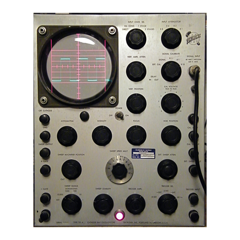
Tektronix Keithley CS-1546 User manual

Tektronix

Tektronix Keithley CS-1546 User manual

Tektronix MSO4000B Series Use and care manual

Tektronix

Tektronix MSO4000B Series Use and care manual

Tektronix DPO2000 Series User manual

Tektronix

Tektronix DPO2000 Series User manual

Tektronix 2440 User manual

Tektronix

Tektronix 2440 User manual

Tektronix TBS1052B-EDU User manual

Tektronix

Tektronix TBS1052B-EDU User manual

Tektronix 7603 User manual

Tektronix

Tektronix 7603 User manual

Tektronix 7603 Operating instructions

Tektronix

Tektronix 7603 Operating instructions

Tektronix TBS1000B Series User manual

Tektronix

Tektronix TBS1000B Series User manual

Tektronix 434 User manual

Tektronix

Tektronix 434 User manual

Tektronix S-2 User manual

Tektronix

Tektronix S-2 User manual

Tektronix 2216 User manual

Tektronix

Tektronix 2216 User manual

Tektronix TAS 455 User manual

Tektronix

Tektronix TAS 455 User manual

Popular Test Equipment manuals by other brands

VOLTCRAFT MS-540 SE operating instructions

VOLTCRAFT

VOLTCRAFT MS-540 SE operating instructions

Phenix Technologies HC2 user manual

Phenix Technologies

Phenix Technologies HC2 user manual

Actron CP7817 Quick manual

Actron

Actron CP7817 Quick manual

Uni-Trend UTD2000E Series manual

Uni-Trend

Uni-Trend UTD2000E Series manual

Agilent Technologies PHD-4 instructions

Agilent Technologies

Agilent Technologies PHD-4 instructions

Ravaglioli R200 manual

Ravaglioli

Ravaglioli R200 manual

PCB Piezotronics 498A-0063 Installation and operating manual

PCB Piezotronics

PCB Piezotronics 498A-0063 Installation and operating manual

Heathkit IG-18 Assembly manual

Heathkit

Heathkit IG-18 Assembly manual

STS 1656 Operator's manual

STS

STS 1656 Operator's manual

Ponovo TD4000A Hardware user manual

Ponovo

Ponovo TD4000A Hardware user manual

FUTABA BR-3000 instruction manual

FUTABA

FUTABA BR-3000 instruction manual

Hanna Instruments HI 98204 instruction manual

Hanna Instruments

Hanna Instruments HI 98204 instruction manual

Aeroflex IFR 4000 Operation manual

Aeroflex

Aeroflex IFR 4000 Operation manual

Gossen MetraWatt DIN VDE 0701 operating instructions

Gossen MetraWatt

Gossen MetraWatt DIN VDE 0701 operating instructions

Soberlink sl2 Training manual

Soberlink

Soberlink sl2 Training manual

Lenoxx BS93 quick start guide

Lenoxx

Lenoxx BS93 quick start guide

Keysight Technologies 16117B Operation and service manual

Keysight Technologies

Keysight Technologies 16117B Operation and service manual

Fluke FTK200 user guide

Fluke

Fluke FTK200 user guide

manuals.online logo
manuals.online logoBrands
  • About & Mission
  • Contact us
  • Privacy Policy
  • Terms and Conditions

Copyright 2025 Manuals.Online. All Rights Reserved.