Auta 721159 User manual

auta
BIOMETRIC + KEYPAD READER
LECTOR BIOMÉTRICO + TECLADO
EN
ES
REF: 721159
RED
NETWORK

Verde - Acceso concedido
Rojo - Acceso denegado
Naranja - Modo inactivo
Pitido de conformidad - pitido corto + largo
Pitido de error - 3 pitidos cortos
Deslizamiento de dedo - 2 pitidos cortos
Indicación
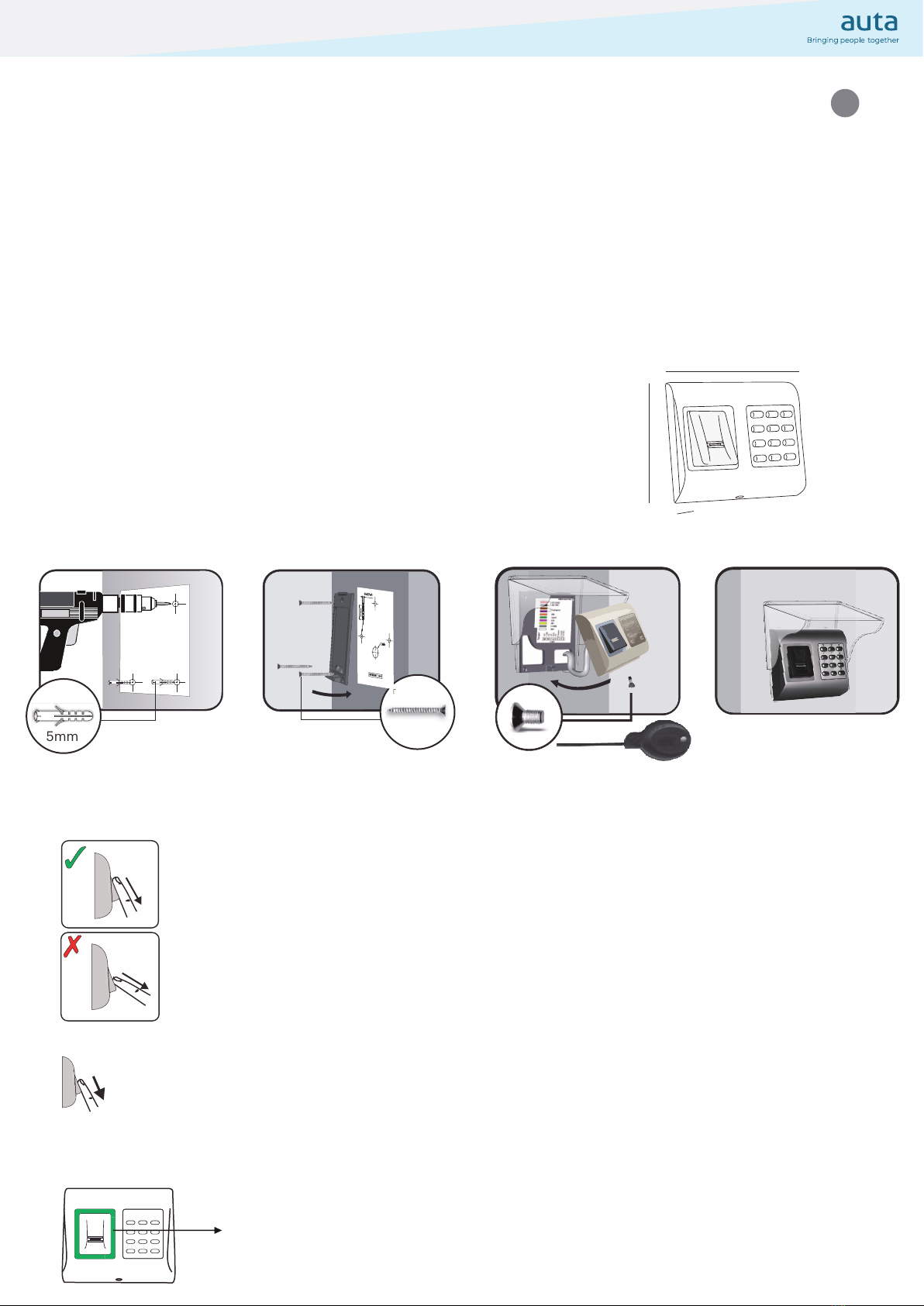
Técnica de deslizamiento recomendada
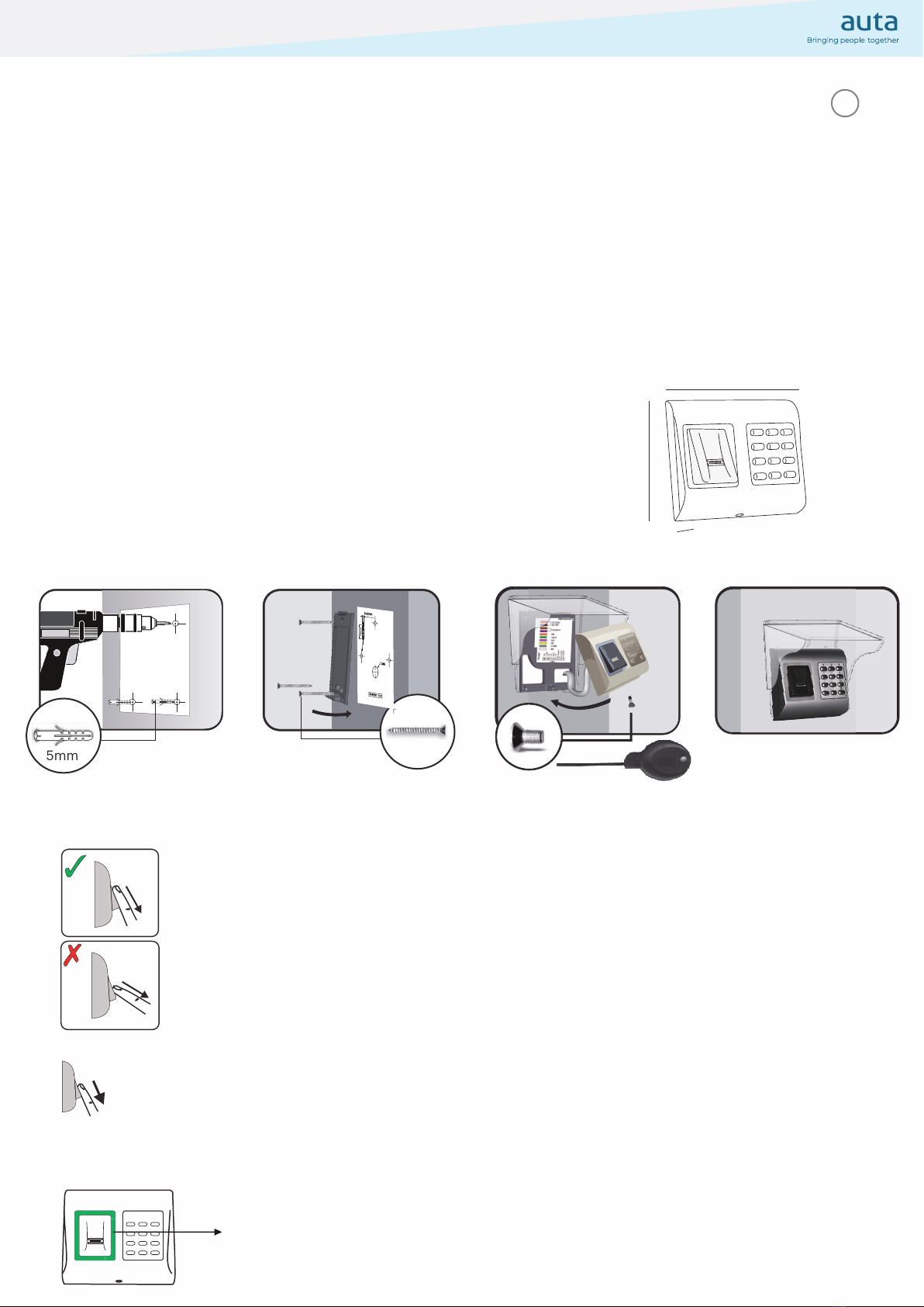
Montaje
Especicaciones
ES
100 mm
94 mm
30 mm
4.
1. 2.
4 (4 x 30mm)
3.
5mm
Tecnología Biometría y eclado
Uso exterior
Interfaz Wiegand 8 a 128 bits; defecto: Wiegand 26
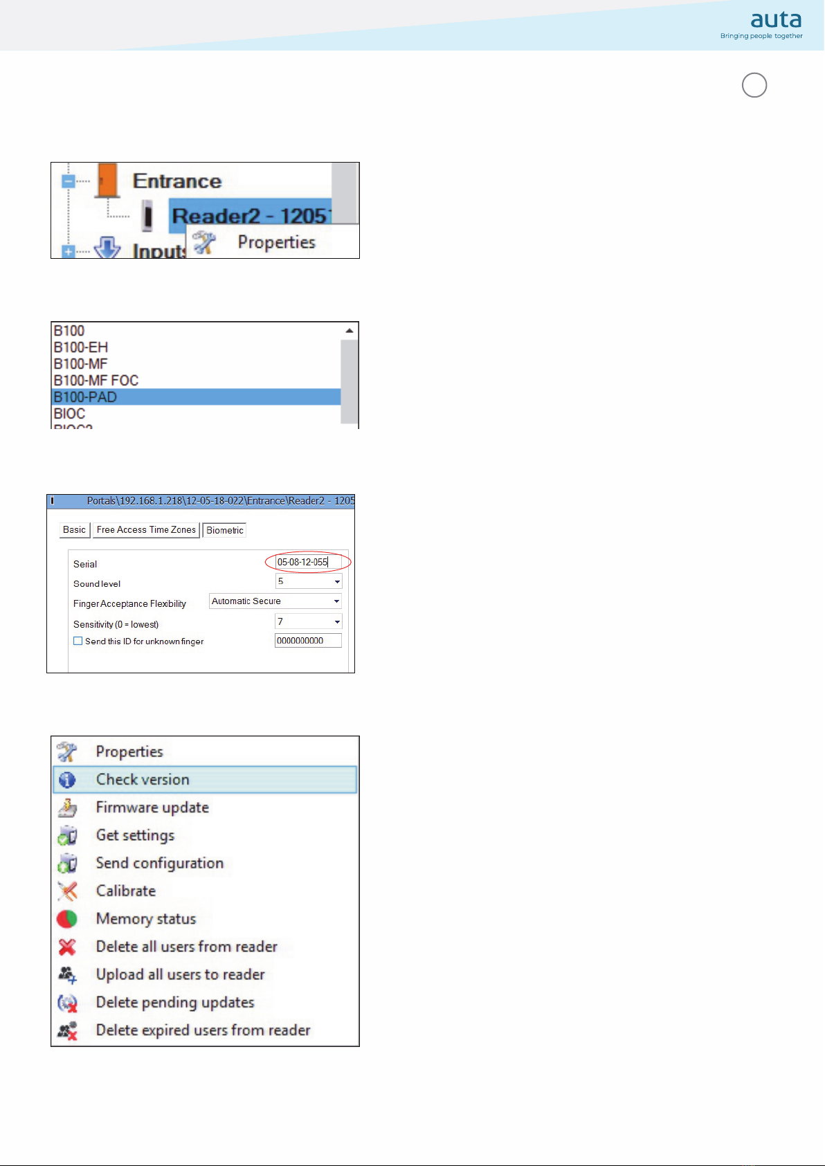
Programación del protocolo Por software
Tipo de sensor de uellas dactilares capacitivo de pasada
Registro de uellas dactilares Sobre el lector o desde el lector de escritorio USB
LED verde y rojo Controlado externamente
LED naranja Modo inactivo
Encendido_Apagado del timbre Si
Consumo 150 mA
Alimentación 914 Vcc
Clasiicación IP IP65
Temperatura de funcionamiento -20°C a +50°C, sin condensación
Dimensiones (mm) 100 x 94 x 30
Carcasa: Aluminio moldeado
Distancia del cable 50m
Retro-iluminado ON_OFF Sí
Capacidad de uellas dactilares hasta 100 huellas dactilares
Huellas dactilares por usuario 110 huellas dactilares
Detección de manipulación: Si
Autenticación Dedo y Código
Tiempo de identiicación 1:1000 970 mseg, incluido el tiempo de extracción de características
Longitud del código PIN 1 a 8 dígitos
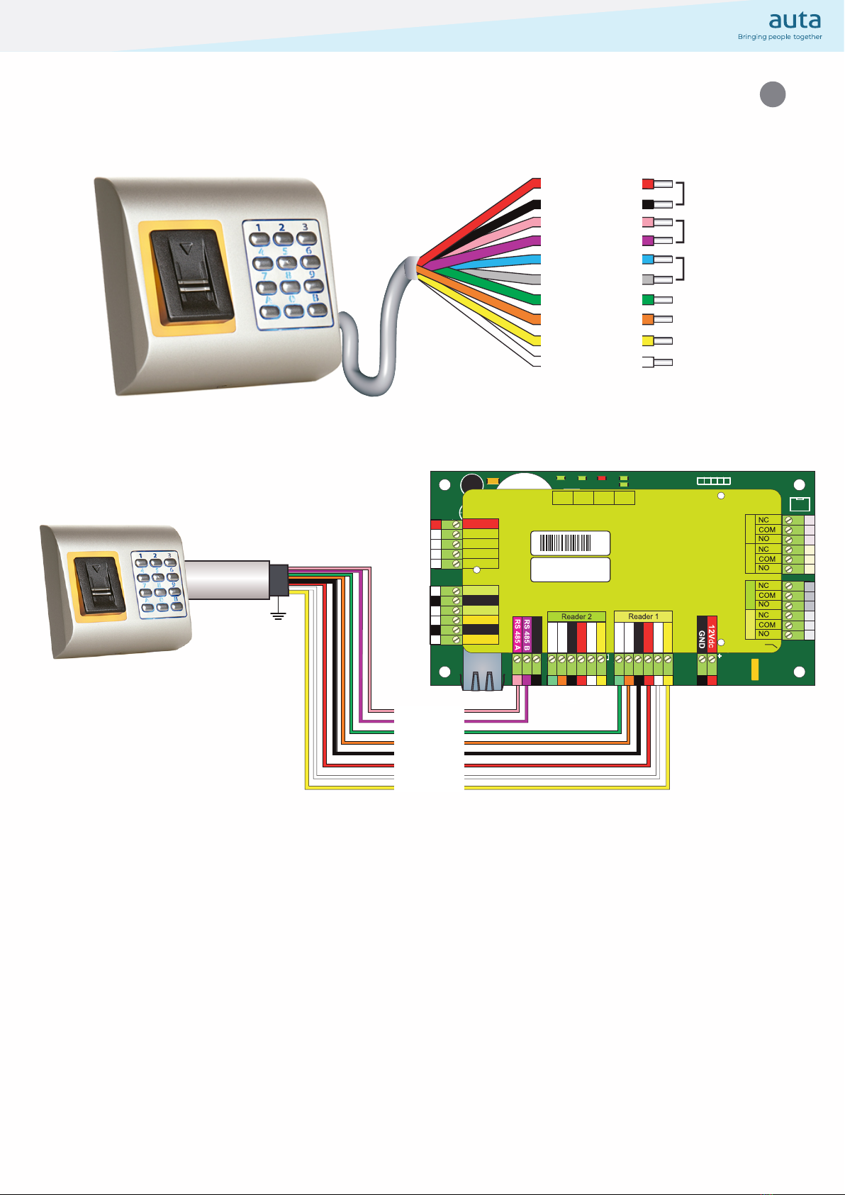
Conexión del panel: Cable, 1 m
Humedad Operativa_Almacenamiento HR del 5% al 93% sin condensación
x 6
Siga las instrucciones siguientes para realizar un deslizamiento de dedo correcto. A partir de la primera
articulación del dedo, se debe colocar el dedo seleccionado en el sensor de deslizamiento y desplazarlo
uniformemente hacia uno mismo en un movimiento continuo.
Resultado:
Deslizamiento válido: LED de estado tricolor se muestra de color verde + Pitido de conformidad (pitido corto +
largo)
Deslizamiento no válido o leído erróneamente: LED de estado tricolor se muestra de color rojo + Pitido de
error ( 3 pitidos cortos)
Las huellas se enrolan en el sistema deslizando el dedo un mínimo de 6 veces.

Cableado
12 Vcc
GND
LR-
D1
D0
LG-
RS485
Tamper NC
A
B
ROJO
NEGRO
ROSA
VIOLETA
AZUL
NARANJA
VERDE
GRIS
AMARILLO
BLANCO
LD16
R55
C41
C28
L2
R36
LD20
R18
R25
R24
C40
R10
C34
L10
L11
C18
C33
R9
C42
C1
R5
R45
C43
C44
R28
R21
C45
D13
LD14
R46 A
C3
C5
R38
ZD3 C29
L9
LD13
R14
ZD4 C32
R19
R37
ALD17 ALD19
ALD18
L7
C27
L6
C16
C15
RX4
D5
D10
R32 R33 LD8 R35
R49
IC6
ZD5
ZD6
R22
L3
R53
R34
TAS1
IC11
R15
IC15
R3
R4
L8
R47
FUSE1
IC8
R20
R16
R11
C2
X1
C4
IC7 ICN2
R1
C13
C12
ICN1
R23
R48
A
LD5
RE1 RE3
A
X3
IC1
C6
U5
L5
L4
RE4RE2
A
LD6 A
LD9
ZD2
LD15
R13
ZD1
R54
R50
R6
IC12 R17
R7
R62
ALD23
D3
D2
RX3
J1
Rb6
R2
LD21
IC2
H1 ALD22
BAT
U1
IC5
FUSE2
IC3
U4
A
A
IC1
A
A
A
Earth
screw
Free Led 1
Free Led 2
GND
12V out
D0
D1
Free Led 1
Free Led 2
GND
12V out
D0
D1
Door Sensor2
Door Sensor1
Exit Button1
Exit Button2
GND
GND
Free In 2 -
Free In 2 +
Free In 1 -
Free In 1 +
Rx Tx Busy System
OK
Door 1 Door 2 Free Out 1 Free Out 2
TCP/IP Earth
12Vdc Out
gnd12V
D1
led2
gnd
12V
D0
led1
12V
IN1 IN1 IN2
IN2
+
-
+
-
D1
led2
gnd
12V
D0
led1
PB2
PB1 DS2DS1
gnd gnd
NO1
COM
NC1 NO2
COM
NC2
NO3
COM
NC3 NO4
COM
NC4
GND
BA
gnd
Fuse
Ser No: 11-04-16-013
Mac: 00-04-A3-16-90-D
RoHS
3361110131
FTP CAT 5/6
100%COBRE
pink
violet
green
orange
black
re
white
yellow
50m. max
B
LG-
D1
D0
+12V
LR-
GND
A
ES

ES
Conectar el teclado a la central de control
Botón DERECHO sobre
el lector en el cual se ha
cableado físicamente
el lector
Botón DERECHO sobre
el lector ya conigurado y
comprobamos su versión de
irmware.
Actualizaremos si es necesario
(FIRMWARE en carpeta de instalación)
Como tipo de lector
seleccionamos B100-PAD
En la pestaña BIOME RÍA
introducimos el número de
serie del lector
(ver INTERIOR tapa trasera)

EN
Green - Access granted
Red - Access denied
Orange - Idle mode
OK beep - short + long beep
ERROR beep - 3 short beeps
Swipe inger - 2 short beeps
Indication
Recommended swipe technique
Mounting
Specications
4.
1. 2.
4 (4 x 30mm)
3.
5mm
100 mm
94 mm
30 mm
Tec nology Biometry and Proximity (125 Khz, EM)
Aut entication Finger and Keypad
Interface Wiegand 8 to 128 bits; Default: Wiegand 26bit
Protocol programming By software
Fingerprint Sensor Type Swipe Capacitive
1:1000 identiication time 970 msec, including feature extraction time
Fingerprint enrolment On the reader or from the USB desktop reader
Panel Connection Cable, 1m
Green and Red LED Externally Controlled
Orange LED Idle mode
Buzzer ON_OFF Yes
Consumption Max. 150mA
Power supply 914 Vdc
IP Rating IP65
Operating Temperature -20°C to +50°C, non-condensing
Dimensions (mm) 100 x 94 x 30
Housing Moulded Aluminium
Storage_Operating Humidity 5% to 93% RH without condensation
Cable distance 50m
Backlig t ON_OFF Yes, by software settings
Fingerprints per user 110 ingerprints
Tamper Yes
PIN code lengt 1 to 8 digits
Use Outdoors
x 6 he ingerprints are enrolled in the system by swiping the inger a minimum of 6 times.
Follow the below instructions for correct inger swiping. Starting from the irst inger joint, place the selected
inger on the swipe sensor and move it evenly towards oneself in one steady movement.
Result:
For a valid swipe: ricolour Status LED turns green + OK Beep(short + long beep)
For an invalid or misread swipe: ricolour Status LED turns red + Error Beep ( 3 short beeps)

EN
Wiring
12 Vdc
GND
LR-
D1
D0
LG-
RS485
Tamper NC
A
B
RED
BLACK
PINK
VIOLET
BLUE
ORANGE
GREEN
GREY
YELLOW
WHITE
LD16
R55
C41
C28
L2
R36
LD20
R18
R25
R24
C40
R10
C34
L10
L11
C18
C33
R9
C42
C1
R5
R45
C43
C44
R28
R21
C45
D13
LD14
R46 A
C3
C5
R38
ZD3 C29
L9
LD13
R14
ZD4 C32
R19
R37
ALD17 ALD19
ALD18
L7
C27
L6
C16
C15
RX4
D5
D10
R32 R33 LD8 R35
R49
IC6
ZD5
ZD6
R22
L3
R53
R34
TAS1
IC11
R15
IC15
R3
R4
L8
R47
FUSE1
IC8
R20
R16
R11
C2
X1
C4
IC7 ICN2
R1
C13
C12
ICN1
R23
R48
A
LD5
RE1 RE3
A
X3
IC1
C6
U5
L5
L4
RE4RE2
A
LD6 A
LD9
ZD2
LD15
R13
ZD1
R54
R50
R6
IC12 R17
R7
R62
ALD23
D3
D2
RX3
J1
Rb6
R2
LD21
IC2
H1 ALD22
BAT
U1
IC5
FUSE2
IC3
U4
A
A
IC1
A
A
A
Earth
screw
Free Led 1
Free Led 2
GND
12V out
D0
D1
Free Led 1
Free Led 2
GND
12V out
D0
D1
Door Sensor2
Door Sensor1
Exit Button1
Exit Button2
GND
GND
Free In 2 -
Free In 2 +
Free In 1 -
Free In 1 +
Rx Tx Busy System
OK
Door 1 Door 2 Free Out 1 Free Out 2
TCP/IP Earth
12Vdc Out
gnd12V
D1
led2
gnd
12V
D0
led1
12V
IN1 IN1 IN2
IN2
+
-
+
-
D1
led2
gnd
12V
D0
led1
PB2
PB1 DS2DS1
gnd gnd
NO1
COM
NC1 NO2
COM
NC2
NO3
COM
NC3 NO4
COM
NC4
GND
BA
gnd
Fuse
Ser No: 11-04-16-013
Mac: 00-04-A3-16-90-D
RoHS
3361110131
FTP CAT 5/6
100%COBRE
pink
violet
green
orange
black
re
white
yellow
50m. max
B
LG-
D1
D0
+12V
LR-
GND
A

EN
Connect the reader to the control unit
RIGH button on the reader
in which he has physically wired
RIGH button on the reader
already conigured and we check
the irmware version
We will update it if necessary
(FIRMWARE ile at installation folder)
As a type of reader
we selected B100-PAD
In the BIOME RY tab
we enter the serial number of
the reader
(see IN ERIOR back cover)

HI-512 _ V 2.0
Table of contents
Languages:
Popular Keypad manuals by other brands

Aritech
Aritech ATS1136 Installation sheet

Bentel Security
Bentel Security Absoluta T-Line Series manual

Honeywell
Honeywell 6280 TouchCenter installation guide

Satel
Satel CR-MF5 Quick installation guide

Honeywell
Honeywell ADEMCO 6160RF user guide

Nortek
Nortek IEI 232e Standalone Installation and programming manual

HIK VISION
HIK VISION DS-PK00-LCD series user manual

Crestron Electronics
Crestron Electronics Zum Wireless Keypad installation guide

Resolution
Resolution RE252T2GIG user manual

Security Command
Security Command SC Series user guide

ACU-RITE
ACU-RITE 200S READOUTS Reference manual

Paradox
Paradox Grafica User quick reference guide