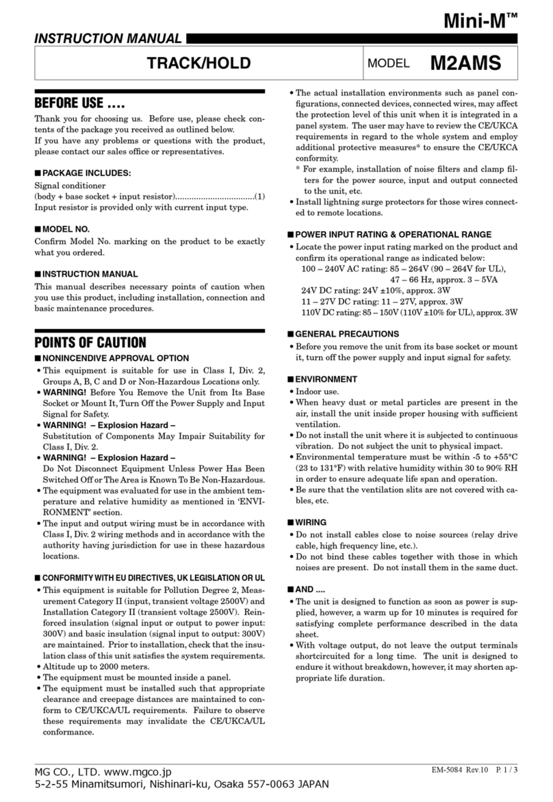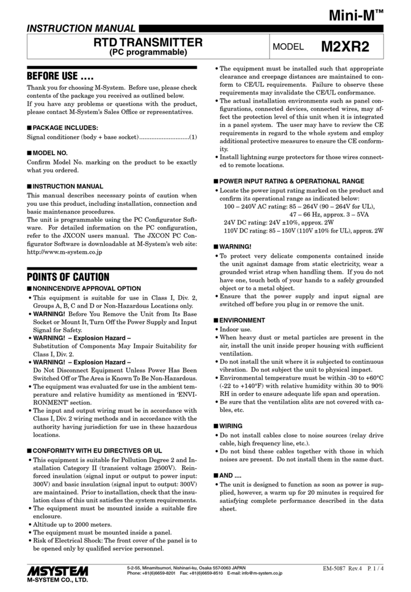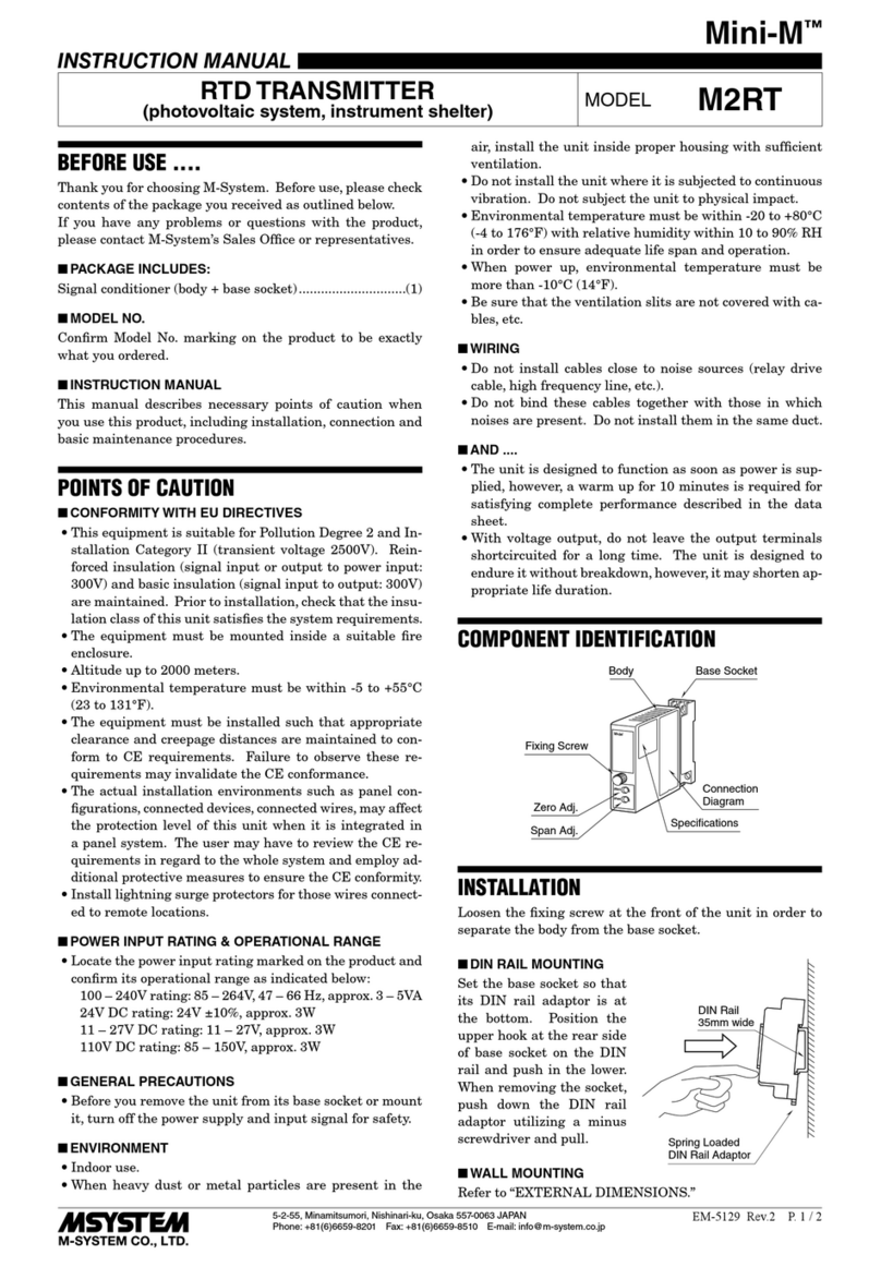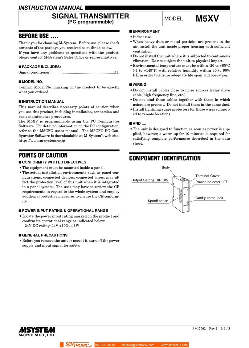
ADJUSTMENT PROCEDURE
This unit is calibrated at the factory to meet the ordered
specifications, therefore you usually do not need any cali-
bration.
For matching the signal to a receiving instrument or in case
of regular calibration, adjust the output as explained in the
following.
■PREPARATION
1) Open the outdoor enclosure cover.
2) Release knurled knobs (A) at the front of the transmitter
and open the top cover.
3) Remove three screws (B), four screws (C), two spring clips
and take out the circuit boards from the housing.
4) After the calibration is complete, refit the spring clips,
screws and close the covers by performing the above pro-
cedure in the reverse order.
AA
B
CC
B
1234
56
SW3 SW2
VR4 VR5
VR1 VR2
TP1 VR3
SW1
SW1 : CJC Selector
SW2 : Zero Bias Selector
SW3 : Span Gain Selector
VR1 : 0% Adjustment (ne)
VR2 : 100% Adjustment (ne)
VR5 : 0% Adjustment (coarse)
VR4 : 100% Adjustment (coarse)
VR3 : CJC Sensor Adjustment
■THERMOCOUPLE TYPE SELECTION
1) Adjust SW1 (rotary code switch) to an appropriate po-
sition for customer’s thermocouple type. Positions are
shown in the illustration below.
3
SS-10
•6
51 42
1 : PR, R, S thermocouples
2 : K (CA) thermocouple
3 : E (CRC) thermocouple
4 : J (IC) thermocouple
5 : T (CC) thermocouple
6 : B thermocouple
■INPUT BIAS ADJUSTMENT (0% temperature)
Check first electromotive force (mV) for 0% (and 100%) tem-
perature in Thermocouple Reference Table.
1) Close across the front terminal 2 – 3 and remove tem-
perature sensor connected to voltage generator as in the
above illustration. (Canceling cold junction compensa-
tion)
2) Connect a digital voltmeter across the front terminal 2
(–) and TP1 (+).
3) With minimum (0%) input, adjust SW2 to appropriate po-
sitions – nearest to desired value – according to Table 1
[INPUT BIAS SELECTION TABLE], and adjust output
reading to 0 ±0.002V with VR5 (zero-coarse adjustment).
4) With minimum (0%) input, adjust output to 0 ±0.05%
with VR1 (zero-fine adjustment).
■INPUT RANGE ADJUSTMENT (100% temperature)
5) With maximum (100%) input, adjust SW3 to appropriate
positions according to Table 2 [INPUT RANGE SELEC-
TION TABLE], and adjust output to 100 ±0.05% with
VR4 (span-coarse adjustment) and VR2 (span-fine ad-
justment).
6) With minimum (0%) input, check that input is 0 ±0.05%.
When the ZERO point is changed, repeat the procedure
2) to 5).
■COLD JUNCTION COMPENSATION ADJUSTMENT
7) Connect temperature sensor to the voltage generator
again and remove shortcircuit across the terminal 2 – 3.
8) With minimum (0%) input, adjust output reading to 0%
with VR3.
■OUTPUT ZERO & SPAN ADJUSTMENT
1) ZERO: Apply 0% input and adjust output to 0% with the
VR1.
2) SPAN: Apply 100% input and adjust output to 100% with
the VR2.
3) Check ZERO adjustment again with 0% input.
4) When ZERO value is changed, repeat the above proce-
dure 1) – 3).
MAINTENANCE
Regular calibration procedure is explained below:
■CALIBRATION
Warm up the unit for at least 10 minutes. Apply 0%, 25%,
50%, 75% and 100% input signal. Check that the output
signal for the respective input signal remains within accu-
racy described in the data sheet. When the output is out of
tolerance, recalibrate the unit according to the “ADJUST-
MENT PROCEDURE” explained earlier.
LIGHTNING SURGE PROTECTION
M-System offers a series of lightning surge protector for
protection against induced lightning surges. Please contact
M-System to choose appropriate models.
6BTS1
5-2-55, Minamitsumori, Nishinari-ku, Osaka 557-0063 JAPAN
Phone: +81(6)6659-8201 Fax: +81(6)6659-8510 E-mail: info@m-system.co.jp
EM-8861 P. 5 / 6
