AUTEC Air series User manual
Original instructions
AIR SERIES
Part C: AJS transmitting unit
INDEX
1 Description ............................................................................................................ 2
2 Technical data ....................................................................................................... 3
3 Technical data sheet ............................................................................................. 3
4 Plates ..................................................................................................................... 4
4.1 Plates on AJS unit in a radio remote control .................................................... 4
4.2 Plates on AJS unit in a Take & Release system ............................................... 4
4.3 Plates on AJS unit in a Multi Units or Multi Receiver system ............................ 5
5 Light signals .......................................................................................................... 6
6 General operating instructions ............................................................................ 7
6.1 Starting up the radio remote control ................................................................. 7
6.2 Command activation ........................................................................................ 8
6.3 Data Feedback Function .................................................................................. 8
6.4 Radio link interruption ...................................................................................... 9
6.5 Transmitting unit automatic switch o .............................................................. 9
6.6 Switching o the transmitting unit ..................................................................... 9
7 Operation ............................................................................................................. 10
7.1 Battery ........................................................................................................... 10
7.2 Air-KEY .......................................................................................................... 11
7.3 START pushbutton ........................................................................................ 12
7.4 STOP pushbutton .......................................................................................... 12
7.5 DISPLAY pushbutton (if the transmitting unit has a display) ........................... 13
8 Malfunction signalled by the transmitting unit ................................................. 14
AUTEC LIAJSE00-00

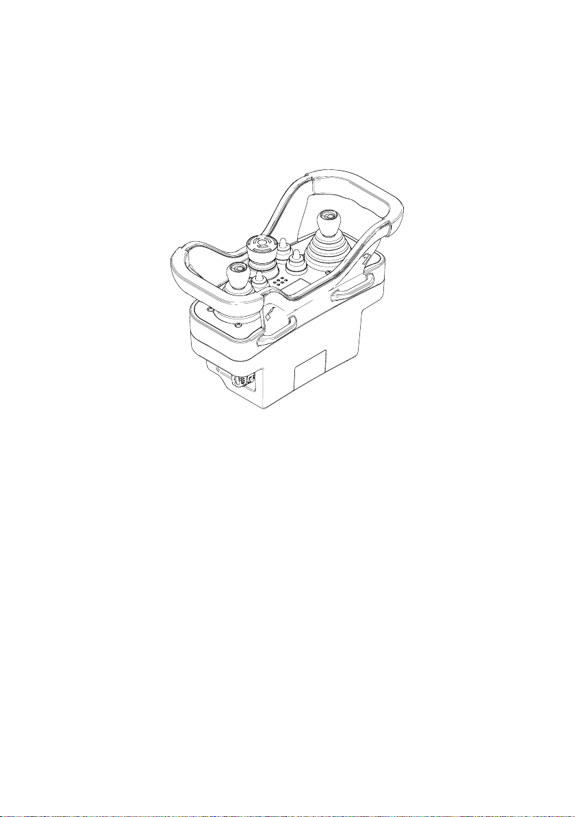
1 Description
TU ID: XXXXXX
MANIF.DATE XXXX
TAXXXX-XX A0TARG01P 0XXX
RADIO MODULE AIRTR42DM
POWER SUPPLY 7.2V
IC: 9061A-AJRDA0BM
FREQUENCY 433.050-434.790MHz
N12335
FREQUENCY 915-928MHz
FCC ID: OQA-AJRDA0BM
This radio device complies with Part 15 of the FCC
Rules.
Operati on is subjec t to the follo wing two
conditions:
(1)this devi ce may notc ause harmful interference,
and
(2) this device must accept any interference
received, includ ing interference that may cause
undesiredoperation.
S/N:
XXXXXX
LM
H
K
G
F
B C
D
J
BYPAS S
RESET
1
1
+
2
2
START
1
2
S
T
O
P
S
T
O
P
S-KEY
3
4
1
1
22
AUX 1 AUX 2
A
DE
ALEDs
BSTOP pushbutton
CDisplay or LED (if present)
DActuators (joysticks, selectors,
pushbuttons)
EFUNCTION pushbutton
FBattery
GTechnical data plate
HTransmitting unit identication plate
JIdentication plate of the radio remote
control or system
KSTART pushbutton
LAir-KEY (electronic starting key)
MBattery housing
2
LIAJSE00-00
Description
AUTEC - Air series

2 Technical data
Power supply (battery LPM02) ..................................................................... Li-Ion 7.4V
Power supply (battery MBM06MH) ............................................................... NiMH 7.2V
Antenna .................................................................................................................. internal
Housing material .......................................................................................... PA 6 (20%fg)
Protection degree ....................................................................................... IP65 (NEMA 4)
Dimensions .................................................................. 258x170x126mm (10.2x7.0x5.0In)
Weight ............................................................................................................. 1.3kg (3Lb)
Run time at 20°C (68°F):
- with battery LPM02 ..................................................................................................... 40h
- with battery LPM02 and Data Feedback function......................................................... 20h
- with battery MBM06MH ............................................................................................... 20h
- with battery MBM06MH and Data Feedback function .................................................. 10h
3 Technical data sheet
The technical data sheet contains the transmitting unit conguration and shows the matching
between commands sent and machine functions/movements. It also contains the wiring
diagram showing the connection between the receiving unit and the machine.
Each technical data sheet must be lled in, checked and signed by the installer, who is
responsible for a correct wiring.
A copy of the technical data sheet must always be kept together with this manual (always
keep a copy of this data sheet for administrative purposes).
The wiring of the receiving unit outputs must always reect the wiring
indicated in the technical data sheet.
AUTEC - Air series
Technical data 3
LIAJSE00-00
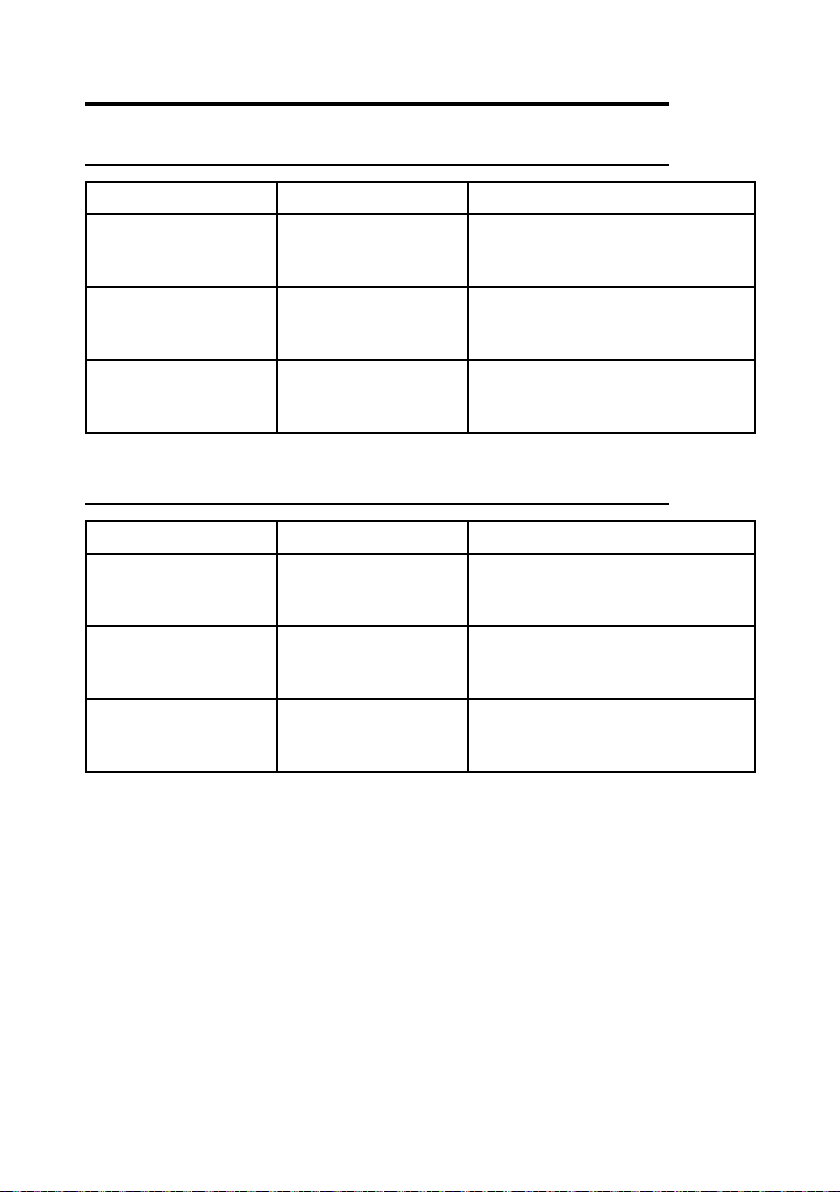
4 Plates
4.1 Plates on AJS unit in a radio remote control
Plate Position Content
radio remote control
identication plate
On the Air-KEY: remove
the Air-KEY to read the
plate.
Radio remote control serial number
(S/N).
transmitting unit
identication plate
In the battery housing:
remove the battery to
read the plate.
Manufacturing year, bar code and
transmitting unit identication number
(TU ID).
technical data plate
In the battery housing:
remove the battery to
read the plate.
MODEL, TYPE and main transmitting
unit technical data, marking and possible
radio remote control marks.
4.2 Plates on AJS unit in a Take & Release system
Plate Position Content
system identication
plate
On the Air-KEY: remove
the Air-KEY to read the
plate.
System serial number (S/N).
transmitting unit
identication plate
In the battery housing:
remove the battery to
read the plate.
Manufacturing year, bar code and
transmitting unit identication number
(TU ID).
technical data plate
In the battery housing:
remove the battery to
read the plate.
MODEL, TYPE and main transmitting
unit technical data, marking and possible
system marks.
4
LIAJSE00-00
Plates
AUTEC - Air series

4.3 Plates on AJS unit in a Multi Units or Multi Receiver system
Plate Position Content
system identication
plate
On the Air-KEY: remove
the Air-KEY to read the
plate.
System serial number (MULTI S/N).
transmitting unit
identication plate
In the battery housing:
remove the battery to
read the plate.
Manufacturing year, bar code and
transmitting unit identication number
(TU ID).
technical data plate
In the battery housing:
remove the battery to
read the plate.
MODEL, TYPE and main transmitting
unit technical data, marking and possible
system marks.
AUTEC - Air series
Plates 5
LIAJSE00-00

5 Light signals
In AJS transmitting units, a green and a red LED are always available, providing information
regarding the radio remote control.
ARed LED
BGreen LED
The green LED… Meaning
…is o. The transmitting unit is switched o.
... is steady on. The transmitting and receiving unit do not communicate.
… blinks fast.
The transmitting and receiving unit communicate. It is
possible to start the radio remote control by pressing the
START pushbutton.
… blinks slowly (one blink per
second). It is possible to send commands.
The red LED … Meaning
…is o. The transmitting unit works correctly.
... is steady on. At start-up, the STOP pushbutton is activated or damaged.
... blinks twice per second. At least one of the commands that were checked at start-
up (see technical data sheet) is enabled or damaged.
... blinks three times per second. At start-up,the battery is at.
... is steady on for 2s. The transmitting unit does not work correctly.
… blinks slowly (one blink per
second). The battery has a 2h run time.
... blinks fast. The battery has a 10min run time.
For other LED signals, see Data Feedback function (paragraph 6.3).
6
LIAJSE00-00
Light signals
AUTEC - Air series
6 General operating instructions
Starting up the radio remote control consists in building a radio link between the transmitting
and the receiving unit.
6.1 Starting up the radio remote control
As required by standard IEC 60204-32, the radio remote control start up is
protected in order to prevent unauthorised use of the machine.
A removable key called Air-KEY guarantees such protection. The radio
remote control cannot work without it.
If the risk assessment requires further protection of the radio remote control
start up, the PIN CODE may be activated.
6.1.1 Start up through Air-KEY (factory setting)
When the receiving unit is powered on, perform the following procedure:
1. Insert a charged battery in the transmitting unit (see paragraph 7.1.1)
2. insert the Air-KEY in the transmitting unit (see paragraph 7.2.1)
3. press the START pushbutton until the green LED blinks slowly.
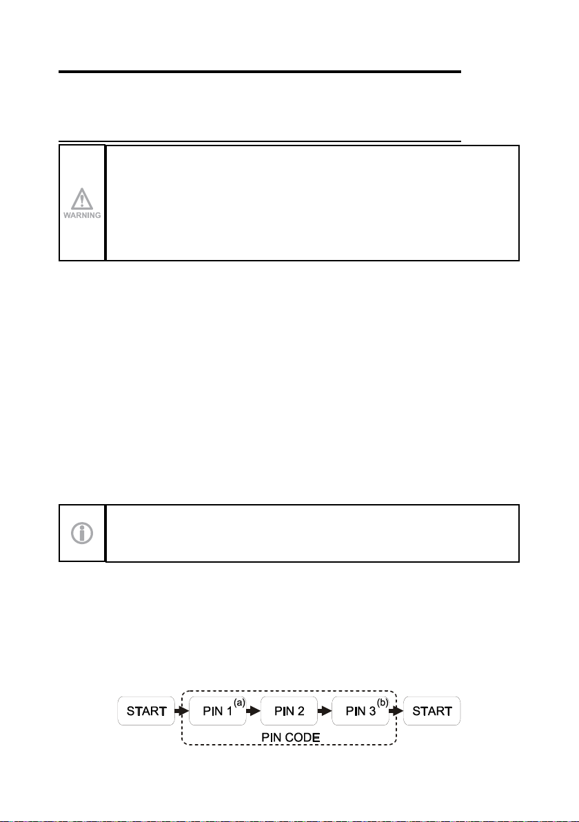
6.1.2 Start up through Air-KEY and PIN CODE
The PIN CODE provides further protection against unauthorized use of the radio remote control.
It consists of a sequence of commands to be carried out by activating the corresponding
actuators during start-up. The radio remote control will start up only with the correct sequence.
The procedure to enable and modify a PIN CODE is provided in the document “Menu of
Transmitting Unit (MTU)”; you can nd this document in the dedicated section on Autec's
website.
When the receiving unit is powered on, perform the following procedure:
1. Insert a charged battery in the transmitting unit (see paragraph 7.1.1)
2. insert the Air-KEY in the transmitting unit (see paragraph 7.2.1).
Consider that the transmitting unit will switch o if more than 3 seconds have
passed between the activation of an actuator and the following one.
3. press the START pushbutton until the green LED illuminates
4. activate the commands corresponding to PIN CODE in the correct sequence (PIN 1, PIN
2 and PIN 3 given in the technical data sheet).
a. PIN 1 shall not be included in the start up procedure if it coincides with the START
command.
b. PIN 3 shall not be included in the start up procedure if it coincides with the START
command.
5. press the START pushbutton until the green LED blinks slowly.
AUTEC - Air series
General operating instructions 7
LIAJSE00-00

6.2 Command activation
With the radio remote control started, act on the joysticks, pushbuttons and switches
corresponding to the command to be performed.
The user must be properly trained about the symbols on the transmitting unit panel, to be
aware of the matching between actuators and movements on the machine (symbols used are
dened by the machine manufacturer according to the functions of the machine).
6.3 Data Feedback Function
The user receives information and/or signals concerning the controlled machine by means
of the Data Feedback function.
During normal radio remote control operation, pay particular attention to the indications
displayed and signalled by the display or through the LEDs: they can be helpful to evaluate
the machine working status.
Any information shown and signalled on the display or through the LEDs
can never be considered or used as a safety signal or for legal metrology.
When operating and moving the machine, remember that the radio remote
control does not intervene autonomously when potential hazardous situations
are displayed and signalled.
6.3.1 Operation with display
If the transmitting unit has a display, it is possible to show signal icons, measurements
collected from the machine and their description.
Information displayed and how it is displayed (icons and/or measurements and/or descriptions)
depend on the settings chosen by the machine manufacturer.
The battery level and the quality of the radio link are also always indicated.
6.3.2 Operation with LED
If the transmitting unit has an LED array, specic machine conditions are signalled if they
are on (i.e. load limits, limit switch, …).
The signalled conditions depend on the settings chosen by the machine manufacturer.
8
LIAJSE00-00
General operating instructions
AUTEC - Air series

6.4 Radio link interruption
When the radio link is incorrect or interrupted, the receiving unit autonomously stops the
radio remote control.
The green LED on the transmitting unit switches from blinking slowly to fast blinking or
steady on.
Press the START pushbutton to start the radio remote control.
6.5 Transmitting unit automatic switch o
The transmitting unit automatically switches o when:
-the battery is at (see paragraph 6.5.1)
-the radio remote control is not used for a certain time (see paragraph 6.5.2)
Press the START pushbutton to start the radio remote control.
6.5.1 Low battery
The transmitting unit indicates if the battery is not suciently charged (the red LED blinks fast).
-The red LED blinks slowly (one blink per second): the battery has a 2 hour run time from
the rst signal.
-the red LED blinks fast: the battery has a 10 minute run time from the rst signal, after
which the transmitting unit automatically switches o.
The battery needs to be replaced with a charged one (see paragraph 7.1).
6.5.2 When the transmitting unit is not used
If the transmitting units remains started with no enabled commands, it will automatically
switch o after a predetermined time frame.This time frame is provided in the technical data
sheet (SWITCH-OFF).
Before the transmitting unit switches o automatically, the green and red LEDs blink alternating
for 30 seconds.
6.6 Switching o the transmitting unit
The transmitting unit shall be switched o each time work is stopped: remove the Air-KEY
(see paragraph 7.2.2) and always store it in a safe place.
AUTEC - Air series
General operating instructions 9
LIAJSE00-00

7 Operation
7.1 Battery
The Air series' transmitting units can only be powered through Autec
rechargeable batteries.
See the battery charger manual enclosed in the packaging with the battery
charger for any warnings and instructions regarding the batteries.
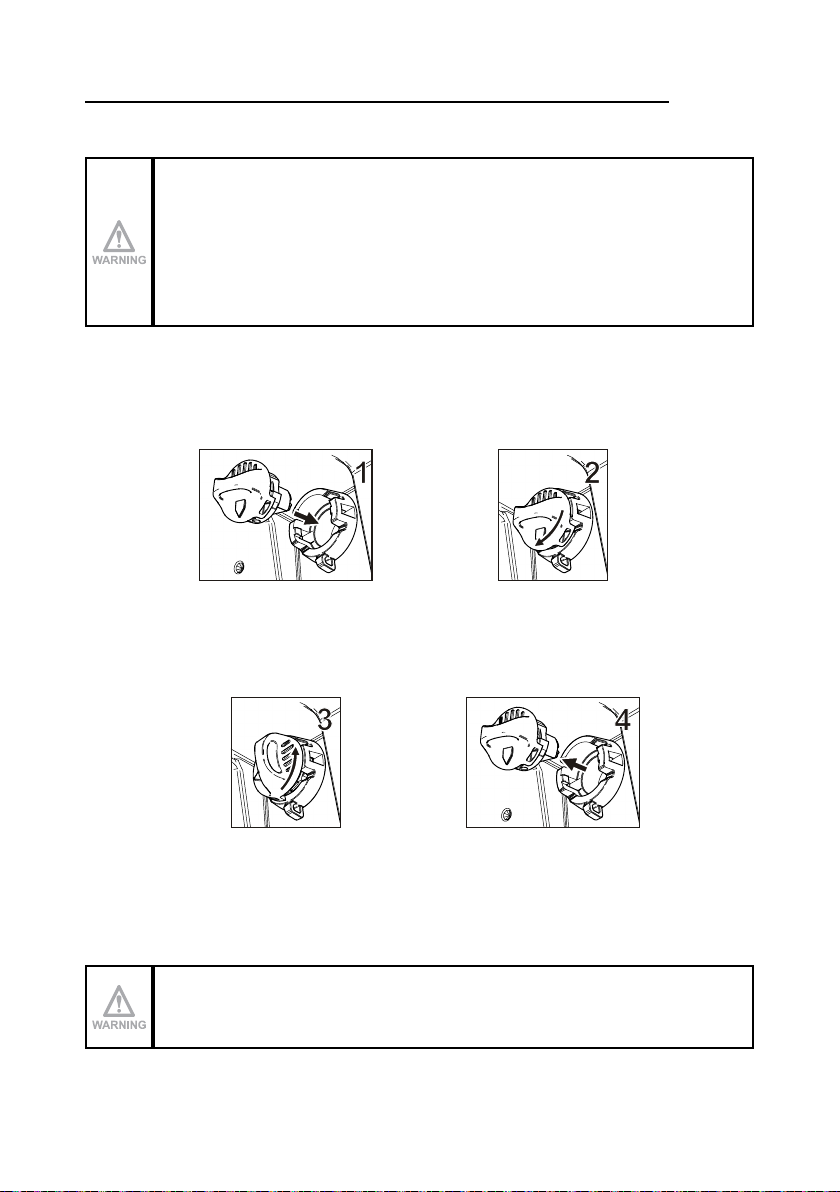
7.1.1 Battery insertion
Push the battery towards the contacts on the transmitting unit (1) and insert it inside the
housing (2).
7.1.2 Battery removal
Push the battery towards the contacts on the transmitting unit (3) and remove it from the
housing (4).
7.1.3 Battery run time indicator
Perform the following procedure to check the run time of the battery in the transmitting unit:
1. switch o the transmitting unit and unlock the STOP pushbutton
2. activate the S1 command (check in the technical data sheet which actuator it corresponds
to) and press the START pushbutton until the LED indicating the battery level illuminates:
-1 LED on: low level
-2 LEDs on: medium level
-3 LEDs on: maximum level.
Run time indication disappears after some seconds.
10
LIAJSE00-00
Operation
AUTEC - Air series
7.2 Air-KEY
In the transmitting unit, the radio remote control address is stored in the Air-KEY. For this
reason, the radio remote control cannot work without this key.
The Air-KEY can only be used in the transmitting unit of the radio remote
control where it belongs.
As the radio remote control address is stored in the Air-KEY, use it with
utmost care to reduce risks that may result from incorrect handling.
7.2.1 Air-KEY insertion
Perform the following operations to insert the Air-KEY:
1. push the Air-KEY inside the corresponding housing
2. rotate the Air-KEY clockwise.
7.2.2 Air-KEY removal
Perform the following operations to insert the Air-KEY:
3. rotate the Air-KEY anticlockwise
4. pull the Air-KEY to remove it from the corresponding housing.
7.2.3 BACK-UP UNIT
If the main transmitting unit cannot be used because it has been lost or damaged, it can be
replaced with a transmitting unit called "BACK-UP UNIT".
It is identical to the unit that cannot be used anymore; the only dierence is the presence of
the plate “BACK-UP UNIT” on the battery housing.
Insert in the "BACK-UP UNIT" the Air-KEY of the transmitting unit that cannot
be used any longer and perform the address storage procedure.
AUTEC - Air series
Operation 11
LIAJSE00-00
Address storage
When the battery is charged and the Air-KEY is in the "BACK-UP UNIT", perform the following
procedure to store the address:
1. press the START pushbutton until the green and the red LEDs illuminate and an acoustic
signal sounds
2. wait until the green LED blinks slowly
3. within 3 seconds, activate in sequence the commands corresponding to PIN 1, PIN 2 and
PIN 3 that compose the PIN code given in the technical data sheet.
If the PIN code is incorrect, the red LED illuminates and the transmitting unit switches o. In
this case, the storage procedure shall be repeated.
If the PIN code is correct, the green LED turns steady on and the transmitting units switches
o: this indicates that the address has been stored in the "BACK-UP UNIT". It is now
possible to start the radio remote control and control the machine with the "BACK-UP UNIT"
transmitting unit.
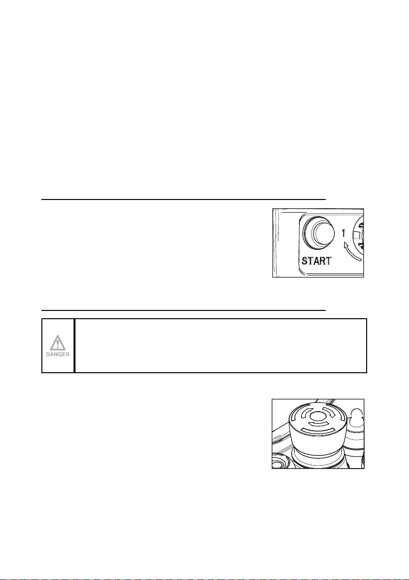
7.3 START pushbutton
The START pushbutton is used to:
-start the radio remote control (see paragraph 6.1)
-activate the horn when the radio remote control is started.
7.4 STOP pushbutton
The STOP pushbutton should be pressed when it is necessary to immediately
stop the machine when a dangerous condition occurs.
When the STOP pushbutton is pressed, the machine stops and
the transmitting unit switches o.
To start working again after the STOP pushbutton has been
pressed:
1. make sure that the working and usage conditions are safe
2. turn the STOP pushbutton in the arrow direction to unlock it
3. start the radio remote control (see paragraph 6.1).
12
LIAJSE00-00
Operation
AUTEC - Air series

7.5 DISPLAY pushbutton (if the transmitting unit has a display)
This pushbutton is used to:
-activate the display lighting, if it is o
-cyclically scroll the information on the display in two dierent
modes
-manual: the lines scroll up each time the pushbutton is
pressed
-automatic: when the DISPLAY pushbutton is pressed for
3 seconds, the lines scroll automatically. If the DISPLAY
pushbutton is pressed another time, it switches back to
manual mode.
It is not possible to scroll the lines if icons only are displayed.
The display lighting stays on for a time set by the machine
manufacturer.
AUTEC - Air series
Operation 13
LIAJSE00-00

8 Malfunction signalled by the transmitting unit
Use the light signals on the transmitting unit to identify the radio remote control malfunction.
If the problem persists after the suggested solution has been carried out, contact the support
service of the machine manufacturer.
Signals Possible reason Solutions
The green LED is steady
on.
The transmitting and
receiving unit do not
communicate.
Start up the radio remote control. If the
radio remote control does not start up,
check that the receiving unit is powered
on.
The green LED blinks
fast.
The radio remote control
is not started up.
Bring the actuators corresponding
to movement commands to the
rest position and press the START
pushbutton until the green LED blinks
slowly.
The green LED blinks
slowly
(one blink per second).
The receiving unit may
not work correctly. See "Receiving unit signals" in Part D.
The red LED is steady
on during start up
The STOP pushbutton is
activated or damaged.
Unlock the STOP pushbutton or contact
the support service.
The red LED blinks
twice per second during
start up.
At least one of the
commands that were
checked at start-up (see
technical data sheet) is
enabled or damaged.
Bring the actuators corresponding to the
commands checked during start up to
the rest position or contact the support
service.
The red LED blinks
three times per second
during start up.
The battery is at. Replace the battery with a charged one.
The green and red LEDs
are steady on and an
acoustic signal sounds
during start up.
The Air-KEY was
inserted in an incorrect
transmitting unit.
Use the correct transmitting unit.
The transmitting unit
has been replaced and
the Air-KEY has been
inserted in the "BACK-UP
UNIT" transmitting unit.
Store the address in the "BACK-UP
UNIT" (see paragraph 7.2.3).
14
LIAJSE00-00
Malfunction signalled by the transmitting unit
AUTEC - Air series

Signals Possible reason Solutions
The green and red LEDs
blink three times per
second during start up.
The Air-KEY is damaged. Contact the support service.
The red LED is steady
on for two seconds.
The transmitting unit does
not work correctly. Contact the support service.
The red LED blinks
slowly
(one blink per second).
The battery has a 2h run
time.
Replace the battery with a charged one
within 2h.
The red LED blinks
quickly.
The battery has a 10min
run time.
Bring the system “machine+radio remote
control“ to a safe state and replace the
battery with a charged one.
The green and red LEDs
blink alternating
30 s left before the
transmitting unit
automatically switches
o.
Activating any actuator corresponding
to a movement command reduces the
predetermined automatic switch-o time
(SWITCH-OFF) to zero.
The green LED blinks
and the red LED is
steady on during start
up.
The procedure
corresponding to the
UNPAIR submenu and
given in the document
"Menu of Transmitting
Unit (MTU)" has been
carried out.
Contact the support service.
AUTEC - Air series
Malfunction signalled by the transmitting unit 15
LIAJSE00-00

Other manuals for Air series
15
Table of contents
Other AUTEC Transmitter manuals


Popular Transmitter manuals by other brands


NCM
NCM NCM-1550-EM30 operating manual

GESTRA
GESTRA TRV 5-40 installation instructions

Electro-Voice
Electro-Voice REV-BP user manual

Philips
Philips Dynalite DIR-TX8 installation instructions

JAROLIFT
JAROLIFT TDRC01W Original assembly and operating instructions

Crestron
Crestron DigitalMedia DM-TX-200-2G Operations & installation guide